
User Manual
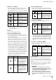
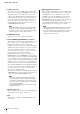
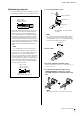
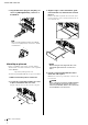
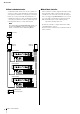
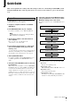
Table Of Contents

Controls and Connectors
MTX5-D Owner’s Manual
11
Switches 1–2 (UNIT ID)
These switches specify the upper digit and the above-
mentioned [UNIT ID] rotary switch specifies the lower
digit, together allowing you to specify one of 63 different
UNIT ID numbers in a range from 01 to 3F.
Switch 3
Not used. Turn it off (up) at any time.
Switch 4 (SECONDARY PORT)
This switch setting determines whether the rear-panel
Dante [SECONDARY] connector will be used for a daisy
chain or redundant network.
With the [DAISY CHAIN] setting, you can connect mul-
tiple Dante-enabled network devices in a daisy chain
without using a network switch. Refer to “Daisy chain
network” in the “About connections” section (see page
15) for more information about daisy chain connections.
With the Dante [REDUNDANT] setting, the Dante [PRI-
MARY] connector will be used for primary connections,
and the Dante [SECONDARY] connector will be used for
secondary (backup) connections. If the unit is unable to
transmit signals through the Dante [PRIMARY] connec-
tor for some reason (e.g., due to damage or accidental
removal of the cable, or a failed network switch), the
Dante [SECONDARY] connector will automatically take
over communications and functions on the redundant net-
work. Refer to “About redundant networks” in the
“About connections” section (see page 15) for more
information on redundant networks.
Switch 5 (PANEL LOCK)
This switch locks the front panel controls. Use this if you
want to prevent accidental operation from the front panel.
Switch 6 (IP SETTING)
This switch specifies how the MTX5-D’s IP address will
be specified.
Switches 7–8 (START UP MODE)
These specify whether the MTX5-D will be initialized
when it is powered-on.
i [DCP] connector
Use this connector to daisy-chain separately sold control
panels such as the DCP1V4S to control the MTX5-D. Use a
CAT5e or better Ethernet straight cable that has all eight pins
connected.
Up to eight control panels can be connected to one MTX5-D.
The total length of the cables from the MTX5-D to the last
control panel must not exceed 200 meters.
Switch position
Option Functions
UNIT ID is
“0x”
The [UNIT ID] rotary switch
will have a setting range of
01 through 0F.
UNIT ID is
“1x”
The [UNIT ID] rotary switch
will have a setting range of
10 through 1F.
UNIT ID is
“2x”
The [UNIT ID] rotary switch
will have a setting range of
20 through 2F.
UNIT ID is
“3x”
The [UNIT ID] rotary switch
will have a setting range of
30 through 3F.
NOTE
Do not use a UNIT ID of “00” (DIP switches 1 and 2 OFF
and the rotary switch at 0).
Switch position
Option Functions
DAISY
CHAIN
The Dante [SECONDARY]
connector is used for a
daisy chain connection. It
can be connected in a daisy
chain by connecting to
Dante [PRIMARY] connec-
tor of the next device.
REDUNDANT
The Dante [SECONDARY]
connector is used for a
redundant network. It will
function as backup connec-
tion, independent of the net-
work to which the Dante
[PRIMARY] connector is
connected.
Switch position
Option Functions
UNLOCK
The front panel controls will
be available for operation.
LOCK
The front panel controls will
be locked, and will be inop-
erable. The device can be
operated from a computer
or an external controller.
Switch position
Option Functions
UNIT ID
The IP address will be
specified according to the
UNIT ID, and will be
192.168.0.(UNIT ID).
PC
The IP address will be
determined by the settings
of MTX-MRX Editor. (See
“MTX-MRX Editor User
Guide.”)
NOTE
You must set this to the “UNIT ID” position the first time
you connect this device to a computer after purchase. If
you subsequently want to specify the IP address instead
of using the UNIT ID, specify the IP address from MTX-
MRX Editor and then switch this setting to the “PC” posi-
tion.
Switch position
Option Functions
RESUME
This is the normal operating
mode. When you power-on
the MTX5-D, it will start up
in the same state in which it
was when the power was
turned off.
INIT.
(INITIALIZE)
Initializes the MTX5-D,
returning it to the factory-set
state (page 22).
CAUTION
• Do not connect a control panel to any connector
other than the MTX5-D’s [DCP] connector. Since the
control panel is not electrically compatible, such con-
nections may cause fire or malfunction.
• Never connect any device to the [DCP] connector
other than the separately sold DCP or other control
panel. Doing so may damage the other device or this
device.