
User Manual


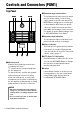


Table Of Contents

Controls and Connectors (PGM1)
10 PGM1/PGX1 Installation Manual
• Switches 4–5
Not used. Leave these in the factory-set
position (upward).
• Switch 6 (IP SETTING)
Specifies how to set the IP address
used for communicating with external
devices.
Switch
Setting UNIT ID is “2x”
Function
The [UNIT ID] rotary switch
setting has a range of 20
through 2F.
Switch
Setting UNIT ID is “3x”
Function
The [UNIT ID] rotary switch
setting has a range of 30
through 3F.
Switch
Setting UNIT ID is “4x”
Function
The [UNIT ID] rotary switch
setting has a range of 40
through 4F.
Switch
Setting UNIT ID is “5x”
Function
The [UNIT ID] rotary switch
setting has a range of 50
through 5F.
Switch
Setting UNIT ID is “6x”
Function
The [UNIT ID] rotary switch
setting has a range of 60
through 6F.
Switch
Setting UNIT ID is “7x”
Function
The [UNIT ID] rotary switch
setting has a range of 70
through 7F.
123
123
123
123
123
123
Switch
Setting UNIT ID
Content
The IP address is determined
by the UNIT ID, and will be
“192.168.0.(UNIT ID)”.
Switch
Setting PC
Content
The IP address is determined
by the setting in MTX-MRX
Editor (see “MTX-MRX Editor
User Guide”).
NOTE
Yo u must set the “UNIT ID” the first time you
connect this unit to a computer after pur-
chase. Also, if you subsequently want to
specify an IP address without using the UNIT
ID, use MTX-MRX Editor to specify the IP
address and then switch to “PC.”
6
6