EN DE FR ES IT RU
Explanation of Graphical Symbols The lightning flash with arrowhead symbol within an equilateral triangle is intended to alert the user to the presence of uninsulated “dangerous voltage” within the product’s enclosure that may be of sufficient magnitude to constitute a risk of electric shock to persons. C A U TI ON RISK OF ELECTRIC SHOCK DO NOT OPEN CAUTION: TO REDUCE THE RISK OF ELECTRIC SHOCK, DO NOT REMOVE COVER (OR BACK). NO USER-SERVICEABLE PARTS INSIDE.
FCC INFORMATION (U.S.A.) 1. IMPORTANT NOTICE: DO NOT MODIFY THIS UNIT! This product, when installed as indicated in the instructions contained in this manual, meets FCC requirements. Modifications not expressly approved by Yamaha may void your authority, granted by the FCC, to use the product. 2. IMPORTANT: When connecting this product to accessories and/or another product use only high quality shielded cables. Cable/s supplied with this product MUST be used. Follow all installation instructions.
PRECAUTIONS PLEASE READ CAREFULLY BEFORE PROCEEDING * Please keep this manual in a safe place for future reference. WARNING Always follow the basic precautions listed below to avoid the possibility of serious injury or even death from electrical shock, short-circuiting, damages, fire or other hazards. These precautions include, but are not limited to, the following: Power supply/Power cord Water warning • Only use the voltage specified as correct for the device.
• Condensation can occur in the device due to rapid, drastic changes in ambient temperature – when the device is moved from one location to another, or air conditioning is turned on or off, for example. Using the device while condensation is present can cause damage. If there is reason to believe that condensation might have occurred, leave the device for several hours without turning on the power until the condensation has completely dried out.
Contents Introduction ........................................................................................................7 Features................................................................................................................................... 7 About Setup ............................................................................................................................. 7 Related manuals and software .........................................................................
Introduction Thank you for purchasing the Yamaha TX6n, TX5n, TX4n Power Amplifier. In order to take full advantage of the TX6n/TX5n/TX4n’s (TXn) functionality and to ensure trouble-free operation, please read this owner’s manual carefully before use. After you have read the manual, keep it in a safe place for reference when needed.
Firmware Updates The firmware version of the TXn itself can be checked from the TXn’s panel and from Amp Editor. You can update the firmware via Amp Editor. For the update procedure, refer to the Amp Editor Owner’s Manual. You can download the latest firmware from the “Downloads” page on the following website. http://www.yamahaproaudio.
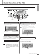
Basic Operation of the TXn Panel Operations Encoder B Function buttons Encoder A About the Display [EXIT] button [HOME] button Adjusting the Attenuator Shows an alert message if a problem occurs or if a user-specified event occurs. When the display shows the attenuator (i.e., in the HOME screen or the METER screen), you can use encoders A and B to adjust each channel’s attenuation. NOTE Shows the contents of the selected screen.
Basic Operation of the TXn Operations that can be Performed from the Panel NOTE • For details, refer to the TX6n/5n/4n Reference Manual. Subcategory Category METER UTILITY MENU Explanation ANA INPUT VOLTAGE Shows the input level from the analog input connectors. SLOT INPUT VOLTAGE Shows the input level from the slot. SP OUTPUT VOLTAGE Shows the output level from the [SPEAKERS] connectors. SP OUTPUT POWER Shows the output power from the [SPEAKERS] connectors.
Audio I/O Settings The TXn can be operated in one of three audio input/output modes: Stereo mode, Parallel mode, or Bridge mode. Make audio input/output connections and settings as follows. NOTE • With the factory settings, if both analog and digital (input from the slot) signals are input simultaneously, the two signal will be mixed and output. This setting can be changed from the panel of the TXn or via Amp Editor.
Audio I/O Settings Bridge Mode The amplifier will operate as a monaural high-power amp, with the input signal of channel A (analog) or channel 1 (digital) as the source. 5-way binding post connectors 2. Use the encoder A to move the cursor (the blinking frame) to “General,” and press the [ENTER] button. 3. Use the function buttons (PREV/NEXT) to access Stereo/Bridge/Parallel screen. – + Analog input Total speaker impedance: 4–16Ω 4.
Wiring of the [SPEAKERS] Connectors Turn off the POWER switch before connecting external devices to the TXn. 5-way Binding Post Connectors No Plugs Speakon Connectors Insert the Speakon cable plug (Neutrik NL4) into the connector, and turn it to the right to lock it. Remove about 13mm of insulation from the end of each speaker cable, and pass the bare wire through the holes in the appropriate speaker terminals. Tighten the terminals to securely clamp the wires.
Network Connection Example If you connect the TXn units’ [NETWORK] connector to a computer via an Ethernet cable, you’ll be able to monitor/control the TXn units from Amp Editor. Including computers and other equipment, a total of up to 253 units can be connected in a single network. Amp Editor IP Address: 192.168.0.253 Ethernet cable Ethernet cable Device ID: 1 IP Address: 192.168.0.1 Device ID: 2 IP Address: 192.168.0.2 Network switch Device ID: 3 IP Address: 192.168.0.
Troubleshooting Symptom No sound from the speaker Possible causes Response The cable is not connected properly. Make the correct connections to the audio input jack and the speaker output jack. The gain or attenuator setting has lowered the level. Gain is adjusted by the MENU screen → General → Sensitivity/Amp Gain. Attenuator is adjusted by turning the encoder in the HOME screen. The [MUTE] button is on.
Specifications General Specifications TX6n Output Power 1kHz, THD + N = 1% 20ms burst TX5n TX4n 120V 230V (*1) 120V 230V (*1) 120V 230V (*1) 8Ω per channel 1800W 1800W 1300W 1300W 1100W 1100W 4Ω per channel 3000W 3000W 2200W 2300W 1900W 2000W 2Ω per channel 2750W 2750W 2500W 2500W 2200W 2200W 8Ω bridge 6000W 6000W 4400W 4600W 3800W 4000W 4Ω bridge 5500W 5500W 5000W 5000W 4400W 4400W 2Ω per channel 4100W 4120W 3480W 3600W 2990W 3050W 4Ω bridge 8200W 8240
Specifications Connectors Analog input AES/EBU input/output In XLR-3-32 type x 2 In XLR-3-31 type x 1 (2 channels, 24-bit 96kHz – 44.1kHz) Thru XLR-3-32 type x 1 (2 channels) Out XLR-3-32 type x 1 (2 channels, 24-bit 96kHz – 44.
TX6n/5n/4n Owner’s Manual CHB CHA CHB CHA CHB CHA CHB CHA FG FG SIGNAL(GR) CLIP(RE) ALERT(OR) MUTE(RE) STANDBY(OR) POWER(WH) PARALLEL(OR) BRIDGE(GR) PROTECTION(RE) NETWORK(GR) IDENTIFY(BL) Channel B Channel A ANALOG AUDIO BA LCD Module Volume Control CHB CHA CHB PowerSW ENTER EXIT HOME FUNCTION MUTE ENCODER CHA EMI FILTER GAIN –10.8dB BA GAIN –10.8dB ANALOG AUDIO Signals [+13.
Specifications Level Diagram DIGITAL INPUT ANALOG INPUT ATTENUATOR DSP INPUT AMP AD POWER AMP DA GAIN ATTENUATOR (all models): 0.0 to -80.0, -∞dB (0.5dB step) GAIN (all models): 19.8 to 43.8dB (0.1dB step) 32.0dB (default) GAIN TX6n Clips (43.8dBu) TX5n Clips TX4n Clips GAIN: 19.8dB (min.) +24.0dBu 0dBFS (digital max.) ATT: 0.0dB Maximum Output Power 43.8dBu (1800W/8Ω) 42.4dBu (1300W/8Ω) 41.2dBu (1000W/8Ω) Model TX6n TX5n TX4n GAIN: 32.0dB (default) +11.
Specifications Dimensions 432 415 17 461 405 41 10 30 429 88 480 Unit: mm 20 TX6n/5n/4n Owner’s Manual
Specifications Current Draw TX6n standby idle 1/8 power 1/3 power TX5n standby idle 1/8 power 1/3 power TX4n standby idle 1/8 power 1/3 power 8ohms/ch 4ohms/ch 2ohms/ch 8ohms/ch 4ohms/ch 2ohms/ch Line Current (A) 100/120V 230/240V 0.36 0.20 1.6 0.88 13.7 7.5 19.2 10.6 22.0 12.1 26.9 14.8 40.4 22.2 44.7 24.
Information for Users on Collection and Disposal of Old Equipment EN This symbol on the products, packaging, and/or accompanying documents means that used electrical and electronic products should not be mixed with general household waste. For proper treatment, recovery and recycling of old products, please take them to applicable collection points, in accordance with your national legislation and the Directives 2002/96/EC.
Yamaha Pro Audio global web site: http://www.yamahaproaudio.com/ Yamaha Manual Library: http://www.yamaha.co.jp/manual/ C.S.G., Pro Audio Division © 2009-2011 Yamaha Corporation 305POZCx.