
User Manual


SWP1 Owner’s Manual
11
Controls and Functions
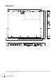
Front panel
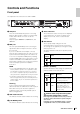
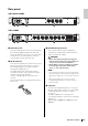
The explanation here is based on the SWP1-16MMF.
1 LAN ports
These are etherCON (RJ-45) ports for connecting
Ethernet cables (CAT5e or better is recommended).
A cable with an RJ-45 connector can also be
connected.
All ports support 1000BASE-T, 100BASE-TX, and
10BASE-T.
2 MMF port
This is an opticalCON DUO port for connecting an
optical fiber cable. LC Duplex connectors can also
be connected.
If you use a cable with an LC Duplex connector,
fasten the dust cap attached to the cable connector
to prevent dust from adhering when the cable is not
in use. You can expand the MMF ports by installing
an optional MMF-SWP1 in the location where a cover
is attached. Installation of the MMF-SWP1 must be
performed by a Yamaha service engineer. Customers
must not attempt to perform the installation
themselves.
NOTE
• Use an opticalCON DUO multi-mode optical fiber cable
mad
e by Neutrik Corporation. Since optical fiber cab
les
ar
e vulnerable to being bent or pulled, you can redu
ce
the occ
urrence of problems by using a cable th
at has a
str
ong sheath and is equipped with a locking mechanism.
• Use GI-type multi-mode fiber cables that have a cor
e
diameter of ap
proximately 50 μm and cladding
diameter
of ap
proximately 125 μm. The maximum length betwe
en
de
vices is 300 m
Cleaning
Correct communication might not be possible if
debris and/or dust has adhered to the ends of optical
fiber cables or the ports. Clean the equipment
regularly by using commercially available optical
fiber cleaning products.
3 LED mode indicators
This indicates what the status indicators are showing.
4 [LED MODE] button
This switches what the status indicators are showing.
5 Status indicators
These indicate the status of each port. The displayed
content depends on the mode. For details on the
display in each mode, refer to “Status indicator
display.”
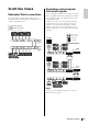
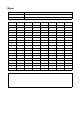
6 DIP switches
These specify startup settings for the unit.
Set the DIP switches when the power is turned off.
The settings are not applied if you change the setting
while the power is on.
The switch illustrations indicate the up/down position
as follows.
• Switch 1 (CONFIG)
Specifies whether the unit’s settings are optimized for
a Dante network or are set by the user.
Caution when using this unit together
with another manufacturer's switch
Dante supports both IGMP V2 and V3, but you must set
all switches in the same network to operate using the
same version.
If the SWP1 starts up with DANTE settings, it operates
using IGMP V3. In this case, if the network includes
12345678
Switch
position
Status
Represent a status with switch toggled up.
Represent a status with switch toggled
down.
Switch
position
Option Functions
DANTE
The unit starts up with settings
optimized for a Dante network.
This setting is read only.
USER
The unit starts up with user
settings. This setting can be
read or written; when you
change the setting, the unit
starts up the next time as well
with that setting.
1
1