
User Manual

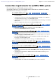

Table Of Contents
- Notice regarding data copyright
- Notice regarding the content of this user guide
- Contents
- Chapter 1. An overview of MTX-MRX Editor
- An audio system control network
- Terms used in this user guide
- Data handled by MTX-MRX Editor
- Connection requirements for an MTX/MRX system
- MTX/MRX system configuration examples
- What are YDIF connections? (Cascade mode and Distribution mode)
- What are Dante connections? (Daisy-chain connection and Star connection)
- Patching
- Workflow
- About the screens
- Moving between screens
- Chapter 2. Menu bar and tool buttons
- Chapter 3. Project screen
- Chapter 4. System screen
- Chapter 5. Online and Synchronization
- Chapter 6. Presets
- Chapter 7. Dialog boxes/Software applications
- “Startup” dialog box
- “Network Setup” dialog box
- “Device Information” dialog box
- “Match Device by IP Address” dialog box
- “MTX Configuration” dialog box
- “Dante Information” dialog box
- “Word Clock” dialog box
- “Clock” dialog box
- “Daylight Saving Time” dialog box
- “Scheduler” dialog box
- “Remote Control” dialog box
- “External Events” dialog box
- “Digital Control Panel” dialog box
- “Wireless DCP” dialog box
- “MCP1” dialog box
- “PIN Setup” dialog box
- “Label” dialog box
- “Re-size Image” dialog box
- “PGM1/PGX1” dialog box
- “PGM1 Label Creator” application
- “GPI” dialog box
- “GPI Calibration” dialog box
- “Security Settings” dialog box
- “Project Information” dialog box
- “Configuration Diagram” dialog box
- “Get Log” dialog box
- “Sampling Rate Converter” dialog box
- “Input Source/Redundant” dialog box
- Appendix

MTX-MRX Editor User Guide
4
Chapter 1.
An overview of MTX-MRX Editor
An audio system control network
When multiple MTX series, MRX series, XMV series, EXi8/EXo8, R series (AD/DA), and Tio1608-D
units are connected to an Ethernet network, they will operate together as a single audio system.
This is
called an “MTX/MRX system,” and a space containing multiple MTX/MRX systems is called a
“project.” If a computer is connected to the network, the computer can control the MTX/MRX system
via the MTX/MRX.
Terms used in this user guide
● YDIF
This is a digital audio transmission format that uses Ethernet cables to send and receive
up to 16 channels of audio and word clock. YDIF makes it easy to connect MTX units
to share buses and expand the number of input/output channels (Cascade mode), or to
connect MRX and XMV/EXi8/EXo8 units so that digital audio signals can be conveyed
without deterioration (Distribution mode).
* If the MRX is part of an MTX/MRX system, only Distribution mode is available.
This format does not include control signals. To send and receive control signals, you
must separately connect the NETWORK connectors.
● Dante
This is a digital audio transmission format developed by the Audinate Corporation that
uses Ethernet cables to send and receive up to 1024 channels of audio together with
word clock and control signals. An MTX/MRX system can use up to 64 channels, and
there can be a maximum of 256 channels for the entire project.
● UNIT ID
This is a unique ID that is assigned to the MTX/MRX, XMV, EXi8, EXo8, PGM1,
MCP1, R series (AD/DA), and Tio1608-D.
The unit ID is specified on the rear panel of each unit. On the MCP1, this is specified
in the utility screen of the unit.
● Panel ID
This is a unique ID assigned to a DCP. It must not conflict between DCP units that are
connected to the same MTX/MRX.
The panel ID is specified for each DCP.
● Components and parameters
Audio processing modules such as equalizers and compressors are called
“components.”
Editable elements of a component are called “parameters.”
● Configuration
This is the basic group of parameters, which you will set first in MTX-MRX Editor.
Here you will specify how audio is patched between the MTX/MRX and the other
external devices.