
User Manual


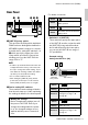

Table Of Contents

Controls and Connectors (PGM1)
9PGM1/PGX1 Installation Manual
Rear Panel
q [UNIT ID] rotary switch
This specifies the ID by which individual
PGM1 units are distinguished within the
MTX/MRX system’s network. In conjunc-
tion with device setting DIP switches 1–3
w which specify the upper place, this
rotary switch specifies the lower place,
allowing you to set the UNIT ID in the
range of 01 to 7F.
w Device setting DIP switches
These switches make settings related to
how the unit starts up. A label explaining
the settings is affixed to the bottom panel.
For details, see below.
• Switches 1–3 (UNIT ID)
These switches specify the upper place
of the UNIT ID; used in conjunction with
the [UNIT ID] rotary switch described
above which specifies the lower place,
you can set the UNIT ID in a range of
127 possibil
iti
es.
Example setting)
Setting the UNIT ID to [0A]
NOTE
•A rubber cap is attached here when the unit
is shipped from the factory; remove the rub-
ber cap to change the switch setting. To pre-
vent dust from entering, reattach the rubber
cap after you have made the setting.
• Do not set the UNIT ID to 00.
• After setting the [UNIT ID] rotary switch,
power-off the PoE injector / PoE network
switch (PSE) and then power it on again.
Making the settings
Before changing the settings, turn off
the power of the PSE. Even if you
change the settings while the power
is on, the changed settings are not
applied until the power is turned off
once.
terwq
Switch
Status
The switch is in the upward
(OFF) position.
Switch
Status
The switch is in the downward
(ON) position.
Switch
Setting UNIT ID is “0x”
Function
The [UNIT ID] rotary switch
setting has a range of 01
through 0F.
Switch
Setting UNIT ID is “1x”
Function
The [UNIT ID] rotary switch
setting has a range of 10
through 1F.
ON
12345678
0A
[UNIT ID]
rotary switch
DIP switches
123
123