Amp Editor Version 1.
Amp Editorとは Amp Editorは、ネットワーク対応アンプ(TXnシリーズ、XMVシリーズなど)、アンプコントロー ルデバイス(ACD1)やアンプコントロールデバイスに接続された対応アンプをコンピューター上でシ ステム構築、モニター /コントロールするためのソフトウェアです。 Amp Editorを使うと接続されている複数の機器を一括してモニター /コントロールできます。 ご注意 ● このソフトウェアおよび取扱説明書の著作権はすべてヤマハ株式会社が所有します。 ● インストールガイドの巻頭にソフトウェアの使用許諾が記載されています。 ソフトウェアをインストールする前に、必ずこのご使用条件をお読みください。 ● このソフトウェアおよび取扱説明書の一部または全部を無断で複製、改変することはできません。 ● このソフトウェアおよび取扱説明書を運用した結果およびその影響については、一切責任を負い かねますのでご了承ください。 ● この取扱説明書に掲載されているイラストや画面は、すべて操作説明のためのものです。 したがって、実際の仕様と異なる場合があります。 ● アプリケーションのバージョンアップなどに
目次 第1章 操作の前に 4 第6章 Tree Viewウィンドウ 102 用語 ......................................................................................................6 ツリー構成 .....................................................................................104 Amp Editorのインストールと設定 .................................................7 Tree Viewウィンドウでの操作 .................................................105 第2章 Amp Editorの概要 第7章 8 メインパネルウィンドウ ...................................................................
第1章 操作の前に 2013年8月現在、Amp Editorで利用できる機器と機能は以下のとおりです。 ● ネットワーク対応アンプ ・ TXnシリーズ(以降TXn):TX6n、TX5n、TX4n ・ XMVシリーズ(以降XMV): XMV4140、XMV4280、XMV8140、XMV8280、 XMV4140-D、XMV4280-D、XMV8140-D、XMV8280-D ● アンプコントロールデバイス ・ ACD1 ● アンプコントロールデバイス対応アンプ ・ ・ ・ ・ XPシリーズ(以降XP):XP7000、XP5000、XP3500、XP2500、XP1000 XMシリーズ(以降XM):XM4180、XM4080 XHシリーズ(以降XH):XH200 PC-1N/PC-Nシリーズ(以降PC-N): PC9501N、PC6501N、PC4801N、PC3301N、 PC2001N、PC9500N、PC4800N、PC3300N ・ Tnシリーズ(以降Tn):T5n、T4n、T3n * 最新の情報については下記URLをご参照ください。 http://www.yamahaproaudio.
第1章 操作の前に モニターコントロールできるパラメーター パラメーター Signal Path View* Analog Input Slot Input Speaker Output Slot Output General TXn ACD1 Tn/PC-N XP/XM/XH XMV コンポーネントのパラメーター操作 ○ ― ― ― レベルメーター ○ ○ ― ― Mute切り替え ○ ― ― ― Pre Inputメーター ○ ― ― ― Mute切り替え ○ ― ― ― レベルメーター (出力電圧) ○ ○ ○ ○ 出力メーター (パワー ) ○ ○ ― ― インピーダンスメーター ○ ○ ― ― アッテネーター操作 ○ ○ ― ○ アッテネーターのLink切り替え ○ ○ ― ― Mute切り替え ○ ○ ○ ○ Solo切り替え ○ ○ ○ ― Polarity(位相反転)切り替え ○** ○ ― ○ レベルメーター ○ ― ― ― 電源Sta
第1章 操作の前に 用語 用語 ワークスペース 定義 Amp Editorが一度にモニター /コントロールできる機器の集合を「ワークスペース」 と呼びます。 機器がコンピューターとネットワーク接続されてAmp Editorと同期していて、モニ ター /コントロールできる状態を「オンライン」と呼びます。機器とコンピューターが 物理的に接続されていないときや、接続されていても同期していない状態を「オフライ ン」と呼びます。 オンライン オフライン シーン 01 アンプA 10 シーン シーンリンク リコール 01 01 アンプB 02 04 Amp Editor シーン 01 アンプC 15 用語 定義 シーン アンプごとの設定を「シーン」と呼びます。シーンを呼び出す(リコール)ことで、保存 した設定をすぐにアンプに反映させることができます。 シーンリンク ワークスペース内の複数のアンプのシーンを同時にリコールするための設定を「シーン リンク」と呼びます。シーンリンクを呼び出す(リコール)ことで、同時に複数のアンプ のシーンをリコールすることができます。シーンリンクの作成
第1章 操作の前に Amp Editorのインストールと設定 Amp Editorを使用して機器をモニター /コントロールするためには、コンピューターにAmp Editorをインストールし、コンピューターと機器のIPアドレスやIDを設定する必要があります。 Amp Editorのインストールについては「Amp Editorインストールガイド」をご参照ください。 コンピューターの設定については「セットアップ」(15ページ)をご参照ください。 機器の設定については各機器の取扱説明書またはリファレンスマニュアルをご参照ください。 各マニュアル類はヤマハプロオーディオサイト(http://www.yamahaproaudio.
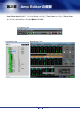
第2章 Amp Editorの概要 Amp Editorは大きく分けて、「メインパネルウィンドウ」「Tree Viewウィンドウ」「Detail View ウィンドウ」の3つのウィンドウから構成されています。 メインパネルウィンドウ Tree Viewウィンドウ Detail Viewウィンドウ Amp Editor 8 取扱説明書
第2章 Amp Editorの概要 メインパネルウィンドウ メインパネルウィンドウはAmp Editorのメインとなるウィンドウです。 NOTE ・ メインパネルウィンドウにプロジェクトファイル(拡張子.
第2章 Amp Editorの概要 Tree Viewウィンドウ Tree Viewウィンドウはネットワークに接続されている機器の接続状態を階層表示するためのウィ ンドウです。 このウィンドウに表示されているアイコンをダブルクリックすると、Detail Viewウィンドウに詳細 情報が表示されます。 詳細については「Tree Viewウィンドウ」(102ページ)をご参照ください。 Amp Editor 10 取扱説明書
第2章 Amp Editorの概要 Detail Viewウィンドウ Detail ViewウィンドウではTree Viewウィンドウで指定されたアンプのモニター /コントロールが できます。 このウィンドウには、以下の4種類の画面があります。 画面名 内容 Device Detail View (115ページ) アンプのアイコンをダブルクリックするか、TreeViewウィンドウやSignal Pathの[Device Detail View]ボタンをクリックすると表示されます。レベル メーターなどのアンプの状態をモニターしたり、アッテネーターやMUTEをコン トロールしたりすることができます。 Signal Path View (TXnのみ)(144ページ) TXnのDevice Detail ViewやTreeViewウィンドウの[Signal Path View]ボ タンをクリックするか、TXnのアイコンを右クリックすると表示されるコンテキ ストメニューで[Show]→[Signal Path View]を選択すると表示されます。この 画面でTXnのコンポーネントのパラメーターを編集するこ
第2章 Amp Editorの概要 プロジェクト Amp Editorで構築したシステムは、プロジェクトとしてフォルダー単位で保存します。 プロジェクトには、ワークスペース、コンポーネント、各パラメーターなどの設定が含まれます。 同時に開くことのできるプロジェクトは1つで、別のプロジェクトを開くと、そのときに開いている プロジェクトは閉じられます。 プロジェクトを開いたり、新規作成、保存したりするためのコマンドは、メインパネルウィンドウの [File]メニューに用意されています。 ■ プロジェクトの新規作成 プロジェクトの新規作成は以下の手順で行ないます。 1. メインパネルウィンドウの[File]メニュー→[New]をクリックします。 新規プロジェクトを作成すると現在開いているプロジェクトが閉じられるため、現在のプロ ジェクトを保存するかどうかを確認するダイアログボックスが表示されます。 2.
第2章 Amp Editorの概要 ● プロジェクトを保存する 1. メインパネルウィンドウの[File]メニュー → [Save]をクリックします。 現在開いているプロジェクトに上書き保存されます。 ● 名前を付けて保存する メインパネルウィンドウの[File]メニュー → [Save As...]は、開いているプロジェクトに名前を 付けて保存します。新規の保存ではプロジェクトが作成され、すでに名前を付けて保存されてい るプロジェクトは別のプロジェクトとして保存します。 1. メインパネルウィンドウの[File]メニュー → [Save As...
第2章 Amp Editorの概要 ■ プロジェクトを開く すでに保存されているプロジェクトを開きます。 プロジェクトを開くと、現在開いているプロジェクトが閉じられるため、現在のプロジェクトを保存 するかどうかを確認するダイアログボックスが表示される場合があります。 ● [Open] 1. メインパネルウィンドウの[File]メニュー→[Open]をクリックします。 フォルダー選択ダイアログボックスが表示されます。 2. 開くプロジェクトのフォルダーを選択します。 3. [OK]ボタンをクリックします。 ● [最近使ったプロジェクト]からプロジェクトを開く メインパネルウィンドウの[File]メニューには最近使ったプロジェクトが表示されます。 プロジェクト名をクリックすると、プロジェクトを開くことができます。 最近使ったプロジェクト ● プロジェクトファイルのアイコンをダブルクリックする プロジェクトフォルダーの中のプロジェクトファイル(拡張子.
第3章 セットアップ Amp Editorを使用して機器をモニター /コントロールするためには、コンピューターと機器のIP アドレスや機器のIDを設定する必要があります。 NOTE ・ 機器のIDとは、機器を識別する番号を表します。機器のIDは、製品によって呼び方が異なります。TXnや ACD1などはDevice ID (10進数)、XMVではUNIT ID (16進数)と呼びます。本書では、製品によってDevice IDとUNIT IDを使い分けて記述しています。 Device IDの設定 機器をAmp Editorで識別するためにDevice IDを設定します。複数の機器がネットワーク内に存在 する場合は、それぞれ別のIDに設定します。 ■ TXnの場合 1. TXnの電源をオンにします。 約10秒経つと、本体フロントパネルのディスプレイにHOME画面が表示されます。 2. 本体フロントパネルの[ENTER]ボタンを1秒以上押し続けます。 Device IDを設定する画面が表示されます。 3.
第3章 セットアップ ■ ACD1の場合 1. ACD1の電源をオンにします。 約10秒経つと、本体フロントパネルのディスプレイにHOME画面が表示されます。 2. 本体パネルの[BACK]ボタンを1秒以上押し続けます。 Device IDを設定する画面が表示されます。 3. 本体フロントパネルの[▲INC/YES]/[▼DEC/NO]ボタンでDevice IDを選択します。選択 できる値は、0〜255です。 1つのネットワークに複数のACD1やTXnを接続する場合は、それぞれ異なるDevice IDを 設定してください。 4. 本体フロントパネルの[NEXT]ボタンを押します。 カーソルが 5. に移動します。 本体フロントパネルの[▲INC/YES]ボタンを押します。 設定した値が本体に反映されます。 NOTE 6.
第3章 セットアップ IPアドレスの設定 Amp Editorと機器間で通信するためにコンピューターと機器のIPアドレスを設定します。 ■ コントロールパネルの表示方法 コントロールパネルの表示方法はOSによって異なります。 ● Windows XP/Vista/7の場合 [スタート] → [コントロールパネル]を選びます。 ● Windows 8の場合 1. スタート画面で[デスクトップ]をクリックします。 デスクトップが表示されます。 2. デスクトップの右上または右下にカーソルを移動します。 チャームバーが表示されます。 3. [設定] → [コントロールパネル]を選択します。 ■ コンピューターのIPアドレス設定 NOTE ・ 特に必要がない限り、IPアドレスはプライベートアドレスに設定してください(192.168.0.2〜 192.168.255.
第3章 セットアップ ● Windows Vista/7/8の場合 1. [コントロールパネル] → [ネットワークと共有センター ]または[ネットワークの状態とタス クの表示]をクリックまたはダブルクリックします。 「ネットワークと共有センター」が表示されます。 2.「ネットワークと共有センター」の左側の「タスク」一覧の中から[ネットワーク接続の管理] または[アダプターの設定の変更]をクリックし、[ローカルエリア接続]をダブルクリックし ます。 「ローカルエリア接続の状態」ダイアログボックスが表示されます。 NOTE ・「ユーザーアカウント制御」ダイアログボックスが表示されることがあります。[続行]また は[はい]ボタンをクリックしてください。 ・「ローカルエリア接続のプロパティ」ダイアログボックスが表示された場合、手順4に進み ます。 3. [プロパティ ]をクリックします。 「ローカルエリア接続のプロパティ」ダイアログボックスが表示されます。 NOTE 4.
第3章 セットアップ ● Windows XPの場合 1. [コントロールパネル]→[ネットワーク接続]→[ローカルエリア接続]を選択してダブルクリッ クします。 「ローカルエリア接続の状態」ダイアログボックスが表示されます。 2. [全般]タブの[プロパティ ]をクリックします。 「ローカルエリア接続のプロパティ」ダイアログボックスが表示されます。 3. [全般]タブの[インターネットプロトコル(TCP/IP)]をダブルクリックします。 「インターネットプロトコル(TCP/IP)のプロパティ」ダイアログボックスが表示されます。 4. [次のIPアドレスを使う]を選択して、[IPアドレス]と[サブネットマスク]を設定します。 推奨値は[IPアドレス]が「192.168.0.253」、[サブネットマスク]が「255.255.255.0」 です。 5.
第3章 セットアップ ■ 機器のIPアドレス設定(TXn, ACD1における典型的なケース) TXn, ACD1においては、Amp EditorのAuto IP Address Assignment機能(92ページ)によっ て自動的に各機器のIPアドレスを割り振り、そのIPアドレスを使用して機器とAmp Editorの間の 通信を行なうことを想定しています。以下はその想定に基づく説明です。 1. (機器の電源を入れる前に)コンピューターのEthernet端子とスイッチングハブをEthernet ケーブルで接続して、コンピューターを起動します。 2. [スタート]→[すべてのプログラム]→[Yamaha Amp Editor]→[Amp Editor]をクリック し、Amp Editorを起動します。 3. Amp Editorのメニューバーから、[System]→[Network Setup]を選択します。 「Network Setup」ダイアログボックスが開きます。 4.
第3章 セットアップ 7. 機器の[NETWORK]端子とスイッチングハブをEthernetケーブルで接続して、すべての機器 の電源をオンにします。 8.
第3章 セットアップ ■ 機器のIPアドレス設定(XMVにおける典型的なケース) XMVにおいては、各機器にユニークに割り当てたUNIT IDの値を元にIPアドレスが自動的に決ま り、そのIPアドレスを使用して機器とAmp Editorの間の通信を行なうことを想定しています。以下 はその想定に基づく説明です。 1. (XMVの電源を入れる前に)コンピューターのEthernet端子とスイッチングハブをEthernet ケーブルで接続して、コンピューターを起動します。 2. [スタート]→[すべてのプログラム]→[Yamaha Amp Editor]→[Amp Editor]をクリック し、Amp Editorを起動します。 3. Amp Editorのメニューバーから、[System]→[Network Setup]を選択します。 「Network Setup」ダイアログボックスが開きます。 4.
第4章 Amp Editorの基本操作例 ここでは、Amp Editorからアンプをコントロールする例として、アンプごとの基本設定を行ない、 複数のアンプをモニター /コントロールするカスタムコントロールパネルを作成したあと、シーンリ ンクで複数のアンプの設定を一括して切り換えるまでの操作例を説明します。 NOTE ・ あらかじめ「セットアップ」(15ページ)によって、コンピューターと機器のIPアドレスやDevice IDを設定 したうえで以下の手順にお進みください。 ・ ACD1とアンプの接続やAMP IDの設定については「ACD1取扱説明書」をご参照ください。 ■ Amp Editorと機器を同期させる Amp Editorで機器をモニター /コントロールするために同期させます。 1. 機器の電源を入れてから、Amp Editorを起動します。 メインパネルウィンドウとTree Viewウィンドウが表示されます。 Tree Viewウィンドウのワークスペースに接続されている機器が表示されます。 NOTE 2.
第4章 Amp Editorの基本操作例 3.
第4章 Amp Editorの基本操作例 ■ アンプごとの基本設定をする アンプのGainやPower Amp Modeなどの基本設定をします。 4. Tree Viewウィンドウのワークスペース内にあるアンプアイコンをクリックします。 [Device Properties]ボタン 5.
第4章 Amp Editorの基本操作例 6.
第4章 Amp Editorの基本操作例 ■ 複数のアンプをモニター /コントロールする 複数のアンプを一括してモニター /コントロールできるように、「System View Creator」ダイア ログボックスを使ってSystem Viewのカスタムコントロールパネルを作成します。 9. [Tools]メニューの[System View Creator...]を選択します。 「System View Creator」ダイアログボックスが開きます。 10. [Name]で作成するカスタムコントロールパネルの名前を編集します。 11. ここでは、[Type]で[Type A]を選択します。 [Type A]では、[Type B]よりも多くの操作子を表示します。 NOTE ・ [Type B]を選択することによって、より多くのアンプを一画面でモニター /コントロール できますが、操作子の数が減ります。 12.
第4章 Amp Editorの基本操作例 TXnのType Aは以下のような構成になっています。 w i q e r t y u q アンプ名 アンプ名を表示します。 w シーン名 アンプのシーン番号とシーン名を表示します。 e チャンネル名 アンプのチャンネル名を表示します。 r アンプ操作部 以下のモニター /コントロールができます。 ・ レベルメーター /GRメーターの表示 ・ MUTEのオン/オフ ・ SOLOのオン/オフ ・ アラート発生の表示 (Device Detail Viewに表示されているアラートインジ ケーターのどれかが点灯すると点灯します。) ・ アッテネーターの操作 t ライブラリー名 アンプのSpeaker Processorのライブラリー名を表示します。 y [EQ]アイコン/[Delay]アイコン/[SP]アイコン クリックすると以下のコンポーネントエディターが呼び出されます。 ・ 8 Band EQ ・ Input Delay ・ Speaker Processor u [Signal Path View]ボタン( ) Signal Path Vi
第4章 Amp Editorの基本操作例 ■ アンプのSpeaker Processorコンポーネント設定を変更する (TXnのみ) アンプのチャンネル単位で、使用するスピーカーに対応したSpeaker Processorコンポーネント設 定(パラメーターセット)を変更します。 14. Speaker Processorコンポーネントの設定を変更したいチャンネルの[SP]アイコンをク リックします。 「Speaker Processor」ダイアログボックスが開きます。 15. [RECALL]ボタンをクリックし、使用するスピーカーに対応したライブラリーを選択します。 Speaker Processorコンポーネントのパラメーターセットが切り替わります。 NOTE ・ DME Designerで作成したライブラリーファイル(拡張子「.cel」)を使う場合は、 「Speaker Processor Library Connverter」(101ページ)でTXn用のライブラリーファイルに変換して ください。 ・ ライブラリーが拡張子付きの場合、拡張子「.ce2」はセキュリティなし、拡張子「.
第4章 Amp Editorの基本操作例 ■ シーンリンクで複数のアンプの設定を一括して切り換える シーンリンクで複数のアンプのシーンを関連付けることによって、複数のアンプのシーンを同時にス トア/リコールできます。 18. メインパネルウィンドウの[Scene Link Manager]ボタンをクリックします。 「Scene Link Manager」ダイアログボックスが開きます。 [Change Scene Link]ボタン [Scene Link Manager]ボタン 19. Scene Linkリストで[01 [No Data]]をクリックして選択します。 01が[No Data]でない場合は、任意の[No Data]のシーンリンクを選んでください。 20.
第4章 Amp Editorの基本操作例 21. [Store]ボタンをクリックします。 シーンリンク名称を入力するダイアログボックスが表示されます。 22.
第4章 Amp Editorの基本操作例 ■ プロジェクトを保存する 作成した各種設定を保存するためにプロジェクトを保存します。 23. メインパネルウィンドウの[File]メニュー→[Save As...]を選択します。 プロジェクト名を入力するダイアログボックスが表示されます。 他のコンピューターでプロジェクトを使用する場合は、[Copy library data from the user library folder]チェックボックスにチェックを入れると、プロジェクトの保存先フォルダーに ライブラリーファイルも保存されますので便利です。 24. プロジェクト名を入力したあと、[OK]ボタンをクリックします。 プロジェクトの保存先を選択するダイアログボックスが表示されます。 NOTE ・ プロジェクトはフォルダー単位で保存します。 25.
第5章 メインパネルウィンドウ 各部の名称と機能 メインパネルウィンドウは、Amp Editorのメインのウィンドウです。 メニューバー タイトル ショートカットボタン NOTE ・ メインパネルウィンドウにプロジェクトファイル(拡張子.
第5章 メインパネルウィンドウ ● [Show/Hide Tree]ボタン Tree Viewウィンドウを表示/非表示します(102ページ)。 ● [Custom Control Panel]ボタン クリックすると表示されるポップアップメニューからカスタムコントロールパネルを選択します。 [New Custom Control Panel]を選択すると、新規のカスタムコントロールパネルを作成できま す(180ページ)。また、[System View Creator...
第5章 メインパネルウィンドウ ■ Scene Link(シーンリンク) シーンリンクの情報が表示されます。シーンリンクをリコールすることで、複数のアンプのシーンを 一括して切り替えることができます。 [Show/Hide Scene Link Manager] ボタン シーンリンク番号/シーンリンク名 [Change Scene Link]ボタン ● シーンリンク番号/シーンリンク名 最後にリコールしたシーンリンクの番号と名前が表示されます。 ● [Change Scene Link]ボタン [▼]をクリックするとリストが表示され、リコールできるシーンリンクを選択できます。選択し たシーンリンクがリコールされます。 ● [Show/Hide Scene Link Manager]ボタン 「Scene Link Manager」ダイアログボックスを開きます(89ページ)。シーンリンクで複数のア ンプのシーンを一括してリコールしたい場合は、リコールしたいシーンをシーンリンクにあらか じめ登録しておく必要があります。 NOTE ・ XMVはシーンに対応していません。 ■ SOLO(Solo M
第5章 メインパネルウィンドウ メインパネルウィンドウのメニュー ■ [File]メニュー コマンド 動作 New 新規プロジェクトを作ります(12ページ)。オンライン時は選択できません。 Open... 保存されているプロジェクトを開きます(14ページ)。オンライン時は選択で きません。 Save プロジェクトを上書き保存します(13ページ)。 Save As... プロジェクトを別のフォルダーに保存します(13ページ)。 Preferences...
第5章 メインパネルウィンドウ ■ [Device]メニュー コマンド 動作 Scene Manager 「Scene Manager」ダイアログボックスを表示します(51ページ)。 Alert Setup... 「Alert Setup」ダイアログボックスを表示します(55ページ)。 Word Clock... 「Word Clock」ダイアログボックスを表示します(59ページ)。 Speaker Processor Library Manager 「Speaker Processor Library Manager」ダイアログボックスを表示します (61ページ)。 Clock... 「Clock」ダイアログボックスを表示します(66ページ)。 Language... 「Language」ダイアログボックスを表示します(67ページ)。 GPI... 「GPI」ダイアログボックスを表示します(69ページ)。 Utility... 「Utility」ダイアログボックスを表示します(76ページ)。 IP Address...
第5章 メインパネルウィンドウ ■ [Tools]メニュー コマンド Synchronization 動作 「Synchronization」ダイアログボックスを表示します(94ページ)。 クリックすると表示されるサブメニューから、ワークスペースに対してソロ機能 (Solo Master)の有効/無効(Enable/Disable)を切り替えます。 また、Mix モードとLastモードを切り替えます。複数のチャンネルを選択して ソロ出力する場合は「Mix Solo」 、最後に選択したチャンネルだけをソロ出力す る場合は「Last Solo」を選択します。 どちらもオンライン時のみ切り替えできます。 Solo Custom Control Panel 「Custom Control Panel Manager」ダイアログボックスを表示します(96 Manager... ページ)。 System View Creator... 「System View Creator」ダイアログボックスを表示します(98ページ)。 Speaker Processor Library Converter...
第5章 メインパネルウィンドウ Preferences [File]メニューの[Preferences...
第5章 メインパネルウィンドウ ● Auto Save プロジェクト自動保存の設定を行ないます。一度も保存されてない場合は無効です。 NOTE ・ 自動保存ではライブラリーファイルはプロジェクトのフォルダーにコピーされません。ライブ ラリーファイルをプロジェクトのフォルダーにも保存する場合は、Fileメニューから[Save]ま たは[Save As...
第5章 メインパネルウィンドウ ■ [Component Editor]タブ コンポーネントエディターのノブとスライダーやエディットボックスの動作を設定します。 ● Knob Mode ノブの操作方法を設定します。 [Circular] ノブの形にそって、円を描くようにドラッグします。 [Linear] 上にドラッグすると値が増え、下にドラッグすると値が減ります。 ● Slider Mode スライダーのバーをクリックしたときの動作を設定します。 [Ramp] スライダーのバー上をクリックしたとき、クリックした方向につまみが一定量移動します。 [Touch] クリックしてもつまみは移動しません。 [Jump] クリックした位置につまみがジャンプします。 Amp Editor 41 取扱説明書
第5章 メインパネルウィンドウ ■ [Meter Unit]タブ Detail ViewウィンドウやDevice Propertiesウィンドウに表示されるメーターやパラメーターの 単位をアンプの種類ごとに設定します。 ● [Analog Input] Analog Inputのレベルメーターの単位を「dBFS」 、「dBu」 、「V」から選択します。 ● [Speaker Output] Speaker Outputのレベルメーターの単位を「dBu」 、「V」から選択します。 ● [Peak Hold]チェックボックス チェックするとレベルメーターのピークホールドを有効にします。ピークホールドは、このAmp Editor上だけに有効な設定です。アンプ本体の設定とは連動しません。 ● [Enable Level Meters]チェックボックス チェックするとレベルメーターが有効になります。 Amp Editor 42 取扱説明書
第5章 メインパネルウィンドウ Event Log 機器本体のイベントログを表示したり、コンピューター上のログファイルへの書き込みを設定した り、機器本体に保存するイベントログを設定したりします。 ■「Event Log」ダイアログボックス [View]メニューの[Event Log]をクリック、またはショートカットボタンの[Show/Hide Event Log]をクリックすると、「Event Log」ダイアログボックスが表示されます。オンライン状態でダ イアログボックスを開いている間、リアルタイムにオンラインで接続されているすべての機器の新し いイベントログが表示されます。「Log Setup」ダイアログボックスで[Enable]がオンの場合は、 同時にコンピューター上のログファイルにも書き込まれます。 NOTE イベントログリスト ・ 表示するイベントログは、「Alert Setup」ダイアログボックスで機器ごとに設定します (55ページ)。 表示/非表示ボタン (Information/Warning/Error/Fault) ● 表示/非表示ボタン(Information/Warnin
第5章 メインパネルウィンドウ ● イベントログリスト 発生したイベントを表示します。 表示されているイベントをダブルクリックすると、該当するイベントが発生した機器の 「Individual Event Log」ダイアログボックスが表示され、詳細な情報が表示されます。 項目の名称表示部を右クリックするとコンテキストメニューが表示され、項目ごとに表示/非表 示を切り替えられます。 NOTE ・ 同じイベントが連続した場合、1行にまとめて表示します。 [Alert] イベントアイコンとイベントの内容を表示します。イベントアイコンは以下の5種類です。 : その他のイベント : 警告イベント : エラーイベント : 障害イベント : 継続するイベントが終了 [Status] イベントの状態を表示します。 イベントが発生するとOccurredと表示されます。継続するイベントが終了するとResolved と表示されます。継続するイベントとは、パラメーターがあるしきい値を超えている場合など に連続して発生するイベントのことです。 [Device] 機器の名称を表示します。 [ID] 発生したイベン
第5章 メインパネルウィンドウ ■「Individual Event Log」ダイアログボックス 「Event Log」ダイアログボックスのイベントをダブルクリック、あるいはTree Viewウィンドウの ワークスペースで機器アイコンを右クリックして呼び出したコンテキストメニューから[Individual Event Log]を選択すると、 「Individual Event Log」ダイアログボックスが表示されます。 「Individual Event Log」ダイアログボックスには選択された機器で発生したイベントが表示されま す。 ● Device イベントを表示している機器名が表示されます。 ● Network Status イベントを表示している機器のネットワーク状態がアイコンで表示されます。 ● IP Address イベントを表示している機器のIPアドレスが表示されます。 Amp Editor 45 取扱説明書
第5章 メインパネルウィンドウ ● イベントログリスト 機器で発生したイベントを表示します。 「Event Log」ダイアログボックスから呼び出した場合は、選択したイベントを展開表示します。 Tree Viewウィンドウから呼び出した場合は、その機器の全イベントを表示します。 NOTE ・ このログリストはリアルタイムに更新されません。「Individual Event Log」ダイアログを閉じ てから開き直すと、その時点の最新情報に更新されます。 Alert イベントの内容を表示します。[Alert]をクリックすると、イベントの内容別に並び替えます。 Status イベントの状態を表示します。 イベントが発生するとOccurredと表示されます。継続するイベントが終了するとResolved と表示されます。[Status]をクリックするとOccurredとResolved別に並び替えます。 Date/Time 機器に保存されているイベントの発生日時を表示します。 Log ID 発生したイベントのログIDを表示します。新しいイベントが発生したり、イベントのタイプが 変わったりするたびに
第5章 メインパネルウィンドウ ■「Log Setup」ダイアログボックス 「Event Log」ダイアログボックスの[Log Setup]ボタンをクリックすると、 「Log Setup」ダイア ログボックスが表示されます。機器本体からイベントログを自動的に取得してファイルに保存した り、手動でまとめて保存したりすることができます。[OK]ボタンをクリックすると、設定を変更し てダイアログボックスを閉じます。 [Log file setup]タブ ● [Enable logging]チェックボックス 取得したイベントログを自動的にファイルに書き込む機能をオン/オフします。チェックすると、 取得したイベントログを指定したフォルダーのファイルに以下のタイミングで書き込みます。 ・Amp Editorを終了するとき ・Amp Editorが起動した状態で午前0時になったとき ・取得したイベントログ数が2,560を超えるとき チェックを外しても機器本体にはイベントログは保存されますが、機器本体の容量を超えた場合 は古いログから順に新しいログで上書きされて消えます。 Amp Editor 47 取扱説明書
第5章 メインパネルウィンドウ [Automatically delete log files after ̲̲ days] チェックすると、指定した日数を経過したログファイルは自動的に削除されます。ログファイ ルを自動的に削除する日数を指定します。 [Log file folder] ログファイルを保存するフォルダーを指定します。[Browse]ボタンをクリックすると、OS 標準のフォルダー指定ダイアログボックスが開き、フォルダーを選択できます。 ログファイルは、「LOG+開始日付.txt」のファイル名で保存されます。ファイルサイズが規 定のサイズを超えた場合は、ファイル名の最後に番号がつけられ、別のファイルとして保存さ れます。(例:LOG20091024-2.
第5章 メインパネルウィンドウ Device Information [View]メニューの[Device Information]をクリック、またはショートカットボタンの[Show/Hide Device Information]をクリックすると、 「Device Information」ダイアログボックスが表示され ます。 オンライン状態に関係なく、ワークスペース内のネットワーク接続している機器の状態を一覧表示し ます。トラブル発生時やシステムメンテナンス時など、機器の稼働状況を一括管理するためのプラッ トフォームとして便利です。 NOTE ・ ACD1に接続されたアンプは表示されません。 ● [Reboot]チェックボックス チェックボックスをオンにして[Reboot]ボタンをクリックすると、複数のアンプをまとめて再起 動できます。チェックボックスをオンにすると、「Firmware Update」ダイアログボックス(86 ページ)の該当する機器の[Device]チェックボックスもオンになります。 ● [Device] 機器に付けられた名称を表示します。 ● [Model] 機器のモデル名(T
第5章 メインパネルウィンドウ ● [IP Address] IPアドレスを表示します。 ● [MAC Address] MACアドレスを表示します。 ● [Firmware Ver.] ファームウェアのバージョンを表示します。 ● [MY Card Type] スロットにI/Oカードを装着している場合は、カード名を表示します。 ● [Message] アンプ本体で発生しているメッセージを表示します。最新のメッセージを1つだけ表示し、古い メッセージは表示されません。 ● [Reboot]ボタン リストの[Reboot]チェックボックスで選択しているアンプをまとめて再起動します。 ● [Firmware Update...]ボタン アップデートファイルが入っているフォルダーを選択するダイアログボックスが開きます。フォ ルダーを選択すると「Firmware Update」ダイアログボックスを表示します(86ページ)。 ファームウェアのアップデートを行ないます。 ● [Utility...
第5章 メインパネルウィンドウ Scene Manager ■ シーンとは 電源Standby/Onやミュートなどの各種設定は、「シーン」としてアンプごとに名前を付けて保存で きます。シーンを保存することを「シーンストア」と呼びます。使用する場面ごとのパラメーター設 定を複数ストアし、呼び出して使うことができます。 シーンを呼び出す(カレントシーンにする)ことを「シーンリコール」と呼びます。「Scene Manager」ダイアログボックスでシーンをリコールします。 アンプごとに1つのプリセットメモリーと49のユーザーメモリーからなります。シーン番号「00」 はアンプを初期設定に戻すための読み出し専用のシーンで、プリセットメモリーにデフォルトで設定 されています。シーン番号「01」〜「49」は、設定を記憶できるユーザーメモリーです。 NOTE ・ XMVはシーンに対応していません。 ■「Scene Manager」ダイアログボックス [Device]メニューの[Scene Manager]をクリックするか、Tree Viewウィンドウのワークスペー スにある機器のアイコンを右クリックして表示されるコンテ
第5章 メインパネルウィンドウ ● [Device] ワークスペース内の操作対象となるアンプを選択します。 Network Status アンプのネットワーク状態がアイコンで表示されます。 IP Address アンプのIPアドレスが表示されます。 Current Scene アンプのシーン番号とシーンの名前が表示されます。 ● シーンリスト シーンの内容が表示されます。 [Scene No.
第5章 メインパネルウィンドウ ● [Paste]ボタン カットまたはコピーしたシーンの内容を、リストで選択されているシーンにペーストします。選 択されているシーンは上書きされます。オンライン時、およびシーン00またはカレントシーン 選択時は、ボタンがグレーになり使用できません。 ● [Insert]ボタン カットまたはコピーしたシーンの内容を、リストで選択されているシーンの位置に挿入します。 オンライン時およびシーン00ではボタンがグレーになり使用できません。 選択されているシーン以下は1つ下に移動します。たとえばシーン番号「05」に 「Conference」というシーンがストアされている場合、シーン番号「05」を選択して[Insert] ボタンをクリックすると、挿入されたシーンがシーン番号「05」になり、「Conference」シー ンはシーン番号「06」に移動します。 リストの一番下のシーンにシーンがストアされている場合は、ボタンがグレーになりシーンの挿 入ができません。リストの一番下のシーンの内容を削除してから挿入してください。 NOTE ・ 挿入したシーン番号以降にEMG信号を受信したときに
第5章 メインパネルウィンドウ ■「Recall Safe」ダイアログボックス(TXnのみ) 「Scene Manager」ダイアログボックスの[Recall Safe]ボタンをクリックすると、「Recall Safe」ダイアログボックスが表示されます。シーンリコールによって変更したくないコンポーネン トをアンプごとに設定します。[OK]ボタンをクリックすると、設定を変更してダイアログボックス を閉じます。 NOTE ・ オフライン時のみ変更できます。 ・ コンポーネント以外のシーン情報(電源のStandby/Onなど)は、このダイアログボックスの設定に 関係なくリコールされます。 コンポーネントリスト ● コンポーネントリスト シーンに含まれるすべてのコンポーネントが表示されます。コンポーネントの左にチェックボッ クスがあり、シーンリコールによって変更したくないコンポーネントをチェックします。 ● [Select All]ボタン すべてのコンポーネントのチェックボックスをチェックします。 ● [Deselect All]ボタン すべてのコンポーネントのチェックボックスをオフにします。 Amp
第5章 メインパネルウィンドウ Alert Setup [Device]メニューの[Alert Setup]をクリック、またはTree Viewウィンドウのワークスペースに ある機器のアイコンを右クリックして表示されるコンテキストメニューの[Alert Setup]を選択する と、 「Alert Setup」ダイアログボックスが表示されます。アラートの有効/無効や種類を機器ごとに 設定します。パスワードを設定することで、アラートの設定をロックすることができます。アラート は、Information以外をイベントログとして表示/保存されたり、障害発生時のトリガー信号として 使われます。 NOTE ・ XMVはAlert Setup機能に対応していないため、発生したアラートはすべて表示されます。 ● Device List アラート設定を表示/変更するアンプを表示します。 Alert Group アラートの設定をするアンプの種類を選択します。 デバイスリスト ワークスペースにある機器のうち、Alert Groupで選択されたアンプおよびACD1の情報を表 示します。 ・ [Device] 機器の名
第5章 メインパネルウィンドウ ・ [ID] 機器のDevice IDを表示します。 ・ [IP Address] 機器のIPアドレスを表示します。 ・ [From Device] Alert Group 内で最後にアラートの設定を読み込んだアンプに「*」が表示されます。 [Import from File...
第5章 メインパネルウィンドウ ● Data Transfer Device Listで選択されているアンプとのアラート設定を送受信します。 [From Device]ボタン Device Listで選択されているアンプ本体から、アラート設定を取得します。 [To Device]ボタン Alertで設定されているアラート設定をアンプに送信します。アンプは複数選択できます。 パスワードが設定されている場合、パスワード入力用のダイアログボックスが表示されます。 ● [Change Alert Setup Password...
第5章 メインパネルウィンドウ ■「Alert」ダイアログボックス 「Warning」 、「Error」、または「Fault」に設定したアラートが発生した場合、 「Alert」ダイアログ ボックスが開いて、アラートの内容を表示します。最新のアラートを1つ表示して、新しいアラート が発生すると古いアラートと入れ替わります。 発生したアラートの詳細については「Event Log」ダイアログボックス(43ページ)を開いて確認し てください。 ● アイコン 発生したアラートのタイプをアイコンで表示します。 : Warning(警告) : Error(エラー ) : Fault(障害) ● Device アラートが発生した機器の名称(ラベル)を表示します。 ● Message アラートの内容を表示します。 メッセージの詳細については資料の「アラートメッセージリスト」(207ページ)をご参照くださ い。 ● Status アラートの状態を表示します。 アラートが発生するとOccurredと表示されます。継続するアラートが終了するとResolvedと 表示されます。 ● [Locate This Device
第5章 メインパネルウィンドウ Word Clock(TXnのみ) ■ ワードクロックとは 複数の機器間でデジタルオーディオ信号を送受信するには、お互いの機器でオーディオ信号を処理す るタイミングを一致させなければなりません。たとえ両方の機器が同じサンプリング周波数に設定さ れていても、オーディオ信号を処理するタイミングが同期していなければ、信号が正常に送られな かったり、耳障りなノイズが生じたりします。 デジタルオーディオ信号の処理を同期させるための信号を「ワードクロック」と呼びます。通常は1 台の機器から基準となるワードクロック信号を送信し、その他の機器は受信したワードクロック信号 に同期させます(送信側の機器を「ワードクロックマスター」、受信側の機器を「ワードクロックス レーブ」と呼びます)。 ■「Word Clock」ダイアログボックス [Device]メニューの[Word Clock...
第5章 メインパネルウィンドウ ● Device ワードクロックの設定対象となるアンプを選択します。 ● クロック周波数 選択されているアンプのワードクロック周波数が表示されます。 オフライン時は、右にある[▼]ボタンをクリックしてワードクロック周波数を変更できます。 ● クロックステータス ワードクロックのステータスが色分けして表示されます。 ステータス 意味 有効なワードクロックが入力されていません(マスタークロックに選択できま せん)。 入力信号があり、現在のワードクロックと同期していることを示しています。 入力信号があるが、ワードクロックと同期できない(クロックが異なる)ことを 示しています。 スロットの無効なチャンネルである、アナログI/Oカードが装着されている、 またはカードが装着されていません。 ● スロット情報(Card) スロットに挿入されているカードの名前が表示されます。 ● マスタークロック選択ボタン(Card/Internal) 同期させるワードクロックを1つ選択します。選択できるクロックは、アンプによって異なりま す。グレーで表示されているクロックのボタンは選択できませ
第5章 メインパネルウィンドウ Speaker Processor Library Manager(TXnのみ) [Device]メニューの[Speaker Processor Library Manager]をクリックすると、「Speaker Processor Library Manager」ダイアログボックスが表示されます。 アンプ本体のSpeaker Processorコンポーネントライブラリーを編集したりアイテムを追加したり できます。 編集/追加/コピーの手順は以下となります。 ● ライブラリーを編集する場合 1. Deviceリストで編集するアンプをクリックする。 2. [From Device]ボタンをクリックする。 Libraryリストにアンプ内のSpeaker Processorコンポーネントライブラリーの内容が表示 されます。 3. 編集作業をする。 Libraryリストのアイテムを選択して、[Move Up]/[Move Down]ボタンでアイテムの順番 を移動し、[Delete Item]ボタンでアイテムを削除することができます。[Export Library...
第5章 メインパネルウィンドウ ● ライブラリーをアンプ間でコピーする場合 1. Deviceリストでコピー元のアンプをクリックする。 2. [Copy]ボタンをクリックする。 3. Deviceリストでコピー先のアンプをクリックする。 キーやキーを押しながらクリックすると複数のアンプを選択できます。 4. [Paste]ボタンをクリックする。 Amp Editor上でLibraryリストの内容が貼り付けられます。 5.
第5章 メインパネルウィンドウ ● [Copy]ボタン 選択しているアンプのライブラリーをコピーします。 ● [Paste]ボタン [Copy]ボタンでコピーしたライブラリーを選択しているアンプに上書きします。[Ctrl]キーまた は[Shift]キーを押しながらアンプを選択して[Paste]ボタンをクリックすると、複数のアンプに 一括して上書きします。 ● [From Device]ボタン Deviceリストで選択されているアンプ本体から、ライブラリーを取得します。ネットワークに接 続されていないアンプを選択している場合は、グレー表示になります。 ● [To Device]ボタン Amp Editor上のライブラリーをアンプ本体に送信します。[Amp Editor → Device]ボタンをク リックするとダイアログボックスが表示され、[OK]ボタンをクリックすると送信が開始されま す。ネットワークに接続されていないアンプを選択している場合は、グレー表示になります。 NOTE ・ ライブラリーを送信した場合、アンプ本体のライブラリーは上書きされます。 ● Libraryリスト Deviceリス
第5章 メインパネルウィンドウ ● [Add Item...]ボタン Libraryリストにアイテムを追加します。[Add Item...]ボタンをクリックすると、 「Add Item」 ダイアログボックスが表示されます。 Library追加アイテムリスト Libraryリストに追加したいアイテムを選択します。アイテムファイル名の左横にあるチェッ クボックスをチェックすると、選択されます。 [Browse...]ボタン Library追加アイテムリストにアイテムファイル(拡張子「.ce2」または「.cep」(セキュリ ティあり))を追加します。[Browse...
第5章 メインパネルウィンドウ ● [Delete Item]ボタン 選択されているアイテムをライブラリーから削除します。 ● [Move Up]/[Move Down]ボタン Libraryリストで選択されているアイテムを上下に移動します。 NOTE ・ [Ctrl]キーまたは[Shift]キーを押しながら複数を選択することで、複数のアイテムを同時に移 動できます。 ● [Import Library...]ボタン ライブラリーアーカイブファイル(拡張子.sla)を、現在選択されているアンプのLibraryリストに 読み込みます。 ● [Export Library...]ボタン 現在選択しているアンプのライブラリーをライブラリーアーカイブファイル(拡張子.
第5章 メインパネルウィンドウ Clock [Device]メニューの[Clock...
第5章 メインパネルウィンドウ ● Clock Data System Clock in This Computer : コンピューターの時計の時刻を表示します。 [Send]ボタン 接続されている機器にコンピューターの時計の時刻を送信して設定します。オフラインでも設 定できます。 [Enable Daylight Saving Time]チェックボックス チェックすると、サマータイム表示が有効になります。また、機器本体ディスプレイの 「Clock Setup」欄に「DST」と表示されます。 ・ [Offset] サマータイム期間に早める時間を設定します。 ・ [Start time] サマータイムの開始時間を設定します。 ・ [End time] サマータイムの終了時間を設定します。開始時間と同じ場合は、[Same as Start time] をチェックします。 NOTE ・ 日付および時刻の表示形式は、Windowsのコントロールパネルの「地域と言語のオプ ション」で変更することができます。「Utility」 、「Event Log」など他のダイアログ ボックスでの表示形式も同様に変更
第5章 メインパネルウィンドウ GPI(ACD1のみ) ■ GPIとは GPIは、General Purpose Interface(汎用インターフェース)の略で、GPI入出力を使うことによ り、カスタムメイドのコントローラーや外部機器から対応機器をリモートコントロールできます。た とえば、GPI INからの入力信号で、シーンを切り替えたり、コンポーネントのパラメーターを変更 したりできます。 GPIの接続方法などについては、それぞれの機器の取扱説明書をご覧ください。 設定できる項目は以下のとおりです。 パラメーター Tn/PC-N XH XP/XM No Assign ○ ○ ○ Scene Recall ○ ○ ○ Mute ○ ○ ○ Standby/On ○ ○ ○ Parameter Value Edit / Direct Parameter Value AttenuationLink Link ○ ― ― ThermalMeter (*) AlertMaxTH ○ ― ― AlertMaxTH ○ ― ― Enable ○
第5章 メインパネルウィンドウ ■「GPI」ダイアログボックス [Device]メニューの[GPI...
第5章 メインパネルウィンドウ [No Assign] どの機能も設定しません。デフォルト(初期値)です。GPI INポートにアサインした機能を クリアするときに選択します。[Device]、[Parameter]、[Min]、[Max]、[Trigger Type]は無効です。 [Scene Recall] 指定のシーンをリコールします。[Device]で変更するアンプを選択します。 「ALL」を選 択すると、その機器に接続されているすべてのアンプを選択します。 [Parameter]でリコールしたいシーン番号を設定します。[Min]、[Max]は無効です。 [Trigger Type]では、GPI INからの入力電圧をどのようにパラメーターに反映させるかを 設定します。 の場合 GPI INへの入力電圧が中央の電圧よりも下から上に変化するときに、[Parameter]で設定した シーンをリコールします。 GPI IN 入力電圧 max 中央の電圧 GPI IN 入力電圧 min トリガー発生 の場合 GPI INへの入力電圧が中央の電圧よりも上から下に変化するときに、[Parameter]で設定し
第5章 メインパネルウィンドウ [Mute] ミュートをオン/オフします。[Device]で変更するアンプを選択します。「ALL」を選択す ると、その機器に接続されているすべてのアンプを選択します。 [Parameter]、[Min]、[Max]は無効です。[Trigger Type]では、GPI INからの入力電圧 をどのようにパラメーターに反映させるかを設定します。 の場合 GPI INへの入力電圧が中央の電圧よりも上のときにミュートをオンし、下のときにミュートをオ フします。 GPI IN 入力電圧 max Mute ON 中央の電圧 GPI IN 入力電圧 min Mute OFF Mute OFF の場合 GPI INへの入力電圧が中央の電圧よりも上のときにミュートをオフし、下のときにミュートをオ ンします。 GPI IN 入力電圧 max Mute OFF 中央の電圧 GPI IN 入力電圧 min Mute ON Mute ON の場合 GPI INへの入力電圧が中央の電圧よりも下から上に変化するときに、ミュートのオン/オフを交 互に切り替えます。 GPI IN 入力電圧
第5章 メインパネルウィンドウ [Standby/On] 電源のStandby/Onを切り替えます。[Device]で変更するアンプを選択します。 「ALL」 を選択すると、その機器に接続されているすべてのアンプを選択します。 [Parameter]、[Min]、[Max]は無効です。[Trigger Type]では、GPI INからの入力電圧 をどのようにパラメーターに反映させるかを設定します。 [Parameter Value Edit] コンポーネントのパラメーターを変更します。[Device]で変更するアンプを選択します。 [Parameter]で変更するパラメーター名を設定します。[Min]、[Max]はパラメーターの制 御範囲を設定します。[Trigger Type]では、GPI INからの入力電圧をどのようにパラメー ターに反映させるかを設定します。 は、連続的な値を持つパラメーターを、外部のフェーダー /ノブなどのデバイスで制 御する場合に使用します。 は、オン/オフなどの2値のパラメーターを、外部のスイッチデバイスから制御す る場合に使用します。 の場合 GPI INへの入力電圧に比例し
第5章 メインパネルウィンドウ の場合 GPI INへの入力電圧が中央の電圧よりも下から上に変化するときに、[Min]の設定値と[Max]の 設定値を交互に設定します。 例:ParameterにAttenuationを指定した場合の入力電圧とAttenuationの関係 GPI IN 入力電圧 max 中央の電圧 GPI IN 入力電圧 min [Max]の設定値 [Min]の設定値 [Max]の設定値 の場合 GPI INへの入力電圧が中央の電圧よりも上から下に変化するときに、[Min]の設定値と[Max]の 設定値を交互に設定します。 例:ParameterにAttenuationを指定した場合の入力電圧とAttenuationの関係 [Min]の設定値 [Max]の設定値 [Min]の設定値 GPI IN 入力電圧 max 中央の電圧 GPI IN 入力電圧 min [Direct Parameter Value] コンポーネントのパラメーターを特定の値に変更します。[Device]で変更するアンプを選 択します。 [Parameter]で変更するパラメーター名を設定します。[Max]
第5章 メインパネルウィンドウ ● GPI OUT ポートごとに、機器のどのパラメーターの状態をGPI OUTから出力を行なうか設定します。一番 左の列にはポート番号が表示されます。 Function どの機能の状態をGPI OUTから出力するかを設定します。設定できるタイプは、[No Assign]、[Scene Recall]、[Mute]、[Standby/On]、[Parameter Value Edit]、[Direct Parameter Value]、[Alert]の7種類です。選択する機能によって、[Device]、 [Parameter]、[Threshold]、[Polarity]、[Output Type]の設定内容が変わります。 [No Assign] どの機能も設定せず、GPI OUTからは何も出力しません。デフォルト(初期値)です。 [Output Type]でアラート発生時の出力信号の極性のみ設定できます。[Device]、 [Parameter]、[Threshold]、[Polarity]は無効です。 [Scene Recall] 指定のシーンのリコール状態をGPI
第5章 メインパネルウィンドウ [Mute] 指定したアンプのミュート状態をGPI OUTから出力します。[Device]で変更するアンプ を選択します。「ALL」を選択すると、その機器に接続されているすべてのアンプを選択し ます。 [Parameter]、[Threshold]、[Polarity]は無効です。[Output Type]では、GPI OUTか らどのように出力するかを設定します。 [Standby/On] 指定したアンプの電源Standby/On状態をGPI OUTから出力します。[Device]で変更す るアンプを選択します。「ALL」を選択すると、その機器に接続されているすべてのアンプ を選択します。 [Parameter]、[Threshold]、[Polarity]は無効です。[Type]では、GPI OUTからどのよ うに出力するかを設定します。 [Parameter Value Edit] コンポーネントのパラメーターの状態をGPI OUTから出力します。[Device]で対象とな るアンプを選択します。 [Parameter]で、変更されたときにGPI OUT出力するパラメ
第5章 メインパネルウィンドウ Utility [Device]メニューの[Utility...]をクリック、またはTree Viewウィンドウのワークスペースにある 機器のアイコンを右クリックして表示されるコンテキストメニューの[Utility...]を選択すると、 「Utility」ダイアログボックスが表示されます。機器の各種設定を行ないます。このダイアログボッ クスはオンライン時のみ有効です。 ■ 各タブ共通 ● Device/ID/Model 表示/設定対象の機器をリストから選択します。 ■ [Information]タブ ● Information Battery 内蔵バックアップバッテリーの状態を表示します。「OK」「Low Battery」「No Battery」の 3段階で表示します。 Firmware Version ファームウェアのバージョンを表示します。 Serial No.
第5章 メインパネルウィンドウ ● Network IP Address Mode Amp Editorと通信するときに使用するIPアドレスの設定モードを表示します。 ・UNIT ID (XMVのみ):UNIT IDの値を使用する ・DHCP:Amp EditorやDHCPサーバーから自動設定する ・Manual:Amp Editorから手動設定する 設定の変更は、「Network Setup」ダイアログボックス(91ページ)で行ないます。 IP Address IPアドレスを表示します。IPアドレスの変更は、「Network Setup」ダイアログボックス (91ページ)または「IP Address」ダイアログボックス(84ページ)で行ないます。 MAC Address MACアドレスを表示します。 IP Control Port No. リモートコントロールプロトコルによる外部リモートコントローラーからのリモートコント ロールに使用するEthernetのポート番号を表示します。ネットワーク内に同じポート番号を 使用する機器がある場合は、「IP Control Port No.
第5章 メインパネルウィンドウ ■ [Setup]タブ ● [Misc] Home Screen Mode TXn本体のHOME画面に表示する名称を設定します。 ・ Scene Name シーン名称を表示します。 ・ Sp. Lib.
第5章 メインパネルウィンドウ ● [Scene] Scene Recall TXnおよびACD1本体パネル操作によるシーンリコールを許可(Enable)するかどうかを設定 します。Amp EditorやGPI機器、リモートコントローラーなどの外部機器からのコントロー ルには影響しません。 EMG Scene Setup TXnおよびACD1がEMG(Emergency)信号を外部機器から受信したときにリコールされる シーンのシーンナンバーを設定します。リコールされるシーンを設定しない場合は、OFFを選 択してください。 Last Memory Resume アンプの電源を入れたときに、前回電源を切ったときの状態で起動するか(ON)、電源を切っ たときのシーン番号のシーンをリコールして起動するか(OFF)を選択します。 Amp Editor 79 取扱説明書
第5章 メインパネルウィンドウ ● [Front Panel Operation] Panel 機器本体のパネル操作を制限します。 ・ Normal 操作制限はありません。 ・ View Only 画面の切り替えはできますが、パラメーターの変更操作はできなくなります。 ・ Full Lock ロック解除以外の操作ができなくなります。 ・ Partial Lock ミュート、アッテネーション、ライブラリーの呼び出し以外のパネル操作ができなくなり ます。 MUTE Key(TXnのみ) アンプ本体でのミュート操作を制限します。 Att.
第5章 メインパネルウィンドウ ● [LCD] Contrast(TXnのみ) ディスプレイのコントラストを表示/設定します。設定は0〜100%です。 Backlight(TXn/ACD1のみ) ディスプレイのバックライトの点灯状態を表示/設定します。 ・ ON 常に点灯します。 NOTE ・ 電源の状態がStandbyのときは、Auto OFFと同じ動作となります。 ・ Auto OFF パネル操作すると点灯し、パネル操作が終わってから10秒後に消灯します。 DIMMER(XMVのみ) ・ Priority to Softチェックボックス チェックすると、Amp EditorからリアパネルのLED輝度を変更できます。 チェックをオフにすると、ON/OFFのラジオボタンが無効になり、Amp Editorからリア パネルのLED輝度を変更できません。 Amp Editor 81 取扱説明書
第5章 メインパネルウィンドウ ■ [Date/Time]タブ ● Date/Time 機器の内蔵時計の時間を表示します。設定は、「Clock Setup」ダイアログ(66ページ)で行ない ます。 ● [Enable Daylight Saving Time]チェックボックス 機器のサマータイムの設定を表示します。サマータイムの設定は、 「Clock Setup」ダイアログ (66ページ)で行ないます。 Amp Editor 82 取扱説明書
第5章 メインパネルウィンドウ ■ [GPI]タブ(ACD1のみ) 機器の[GPI]端子の入力電圧検出範囲のキャリブレーションを行ないます。 ポートチェックボックス 最小入力電圧の設定 最大入力電圧の設定 キャリブレーション情報 ● [All Ports]チェックボックス すべてのポートのチェックボックスをチェックします。 ● ポートチェックボックス チェックしたポートをキャリブレーションの対象に設定します。 ● キャリブレーション情報 リアルタイムで入力電圧を表示します。 ● [Reset]ボタン チェックしたポートのキャリブレーションをリセットします。 ● [Max]ボタン チェックしたポートの現在の入力電圧を最大値にセットします。セットした最大値は赤いマー カーで表示します。 ● [Min]ボタン チェックしたポートの現在の入力電圧を最小値にセットします。セットした最小値は青いマー カーで表示します。 Amp Editor 83 取扱説明書
第5章 メインパネルウィンドウ IP Address [Device]メニューの[IP Address...]をクリックすると、「IP Address」ダイアログボックスが表示 されます。オフライン接続されている機器のIPアドレスを1台ずつ設定します。[OK]をクリックす ると、設定を変更してダイアログボックスを閉じます。 NOTE ・ オフライン時のみ設定できます。 ・ [OK]ボタンをクリックすると、機器のIPアドレスを再設定するため、Amp Editorと機器間の通信 が一時的に切れて、Tree Viewウィンドウの機器アイコンがグレー表示になります。そのあと、通 信が再開されAmp Editorが機器を認識すると、Tree Viewウィンドウの機器アイコンがオフライン 状態になります。Amp Editorが機器を認識しない場合は、Tree Viewウィンドウの[Refresh]ボタン をクリックしてください。 ・ [OK]ボタンをクリックすると、IP Address ModeがManualに変更されます。 ・ 特に必要がない限り、IPアドレスはプライベートアドレスに設定してください(192.
第5章 メインパネルウィンドウ IP Control Port No. [Device]メニューの[IP Control Port No....]をクリックすると、 「IP Control Port No.」ダイアロ グボックスが表示されます。リモートコントロールプロトコルによる外部リモートコントローラーか らのリモートコントロールに使用するEthernetのポート番号を機器ごとに設定します。[OK]をク リックすると、設定を変更してダイアログボックスを閉じます。 NOTE ・ オフライン時のみ設定できます。 ・ [OK]ボタンをクリックすると、設定した機器との通信が切れてTree Viewウィンドウの機器アイコ ンが一時的にグレーに変わります。 ● Device ポートを変更する機器を選択します。選択した機器の現在のポート設定が以下に表示されます。 ● IP Control Port No.
第5章 メインパネルウィンドウ Firmware Update(本体ファームウェアのアップデート) [Device]メニューの[Firmware Update]→[Firmware Update...]をクリック、または「Device Information」ダイアログボックスの[Firmware Update...]ボタンをクリックすると、フォルダー 選択ダイアログボックスが開きます。アップデートファイルが入っているフォルダーを選択すると、 「Firmware Update」ダイアログボックスが表示されます。機器本体のファームウェアをアップ デートします。 [Device]メニューの[Firmware Update]→[Recovery Update...]をクリックした場合は、ファー ムウェアの復元(88ページ)を行ないます。 NOTE ・ 最新のファームウェアは、ヤマハ プロオーディオサイトからダウンロードできます。 http://www.yamahaproaudio.
第5章 メインパネルウィンドウ 2. アップデートファイルを含むフォルダーを選択し、[OK]ボタンをクリックします。 「Firmware Update」ダイアログボックスが表示されます。オフラインで接続されている機 器の名前、現在のファームウェアバージョン、IPアドレスが表示されます。 3. アップデートする機器のチェックボックスをチェックします。 [Select All]ボタンをクリックすると、すべての機器をチェックします。[Clear All]ボタンを クリックすると、すべての機器のチェックを外します。 4.
第5章 メインパネルウィンドウ ■ Recovery Update(復元アップデート) 必要に応じて、機器のファームウェアの復元を行ないます。万が一ファームウェアのアップデート中 に電源が切れた場合、そのままではファームウェアが起動しなくなりますので、Recovery Update で復元してください。 NOTE 1. ・ 復元アップデートに使うファームウェアとファームウェアアップデートに使うファームウェアをあ らかじめダウンロードして、圧縮ファイルを解凍しておいてください。 機器の電源を入れます。 2.「Network Setup」ダイアログボックス(91ページ)またはDHCPサーバーで、機器にIPア ドレスを割り当てます。 3. [Device]メニューの[Firmware Update]→[Recovery Update...]をクリックします。 フォルダー選択ダイアログボックスが開きます。 4.
第5章 メインパネルウィンドウ Scene Link Manager(XMV以外) [System]メニューの[Scene Link Manager]をクリックするか、 「Scene Manager」ダイアログ ボックスの[Scene Link Manager]ボタンをクリックするか、メインパネルウィンドウの[Show/ Hide Scene Link Manager]ボタンをクリックすると、「Scene Link Manager」ダイアログボッ クスが表示されます。 ワークスペース内の複数のアンプで、シーンリンクの設定やリコールを行ないます。シーンリンク設 定を行なうことで、複数のアンプで同時にシーンリコールができます。シーンリンクは100個まで 設定できます。 NOTE ・ この機能はAmp Editor上の機能であり、本体パネルや外部機器などからのシーンリコールには影 響しません。 ・ シーンをストア/リコール時に表示されるダイアログボックスは「Preferences」ダイアログボック スで自動的に閉じるように設定できます。(39ページ) Scene Linkリスト シーンリスト ● [De
第5章 メインパネルウィンドウ ● [Link Setup]ボタン シーンリンクの詳細を表示/編集するLink Setup部の表示/非表示を切り換えます。 ● Scene Linkリスト シーンリンクの一覧が表示されます。 ● [Store]ボタン 選択されているシーンリンクを保存します。 [No Data]となっているシーンリンクで[Store]ボタンをクリックすると、シーンリンクの名前 を入力するダイアログボックスが表示されます。 ・ シーンリンクはアンプ本体にはストアされません。 NOTE ・ Label部で[No Data]となっているシーンリンクを選択している状態で、Scene Select部で編 集をせずに[Store]ボタンをクリックすると、ワークスペース内の全アンプでシーンリンクNo.
第5章 メインパネルウィンドウ Network Setup [System]メニューの[Network Setup...
第5章 メインパネルウィンドウ ■ Network Interface ● [Network Interface]ボックス 接続したい機器と接続しているネットワークインターフェースカードを選択します。 ● IP Address/Subnet Mask 選択したネットワークインターフェースカードに設定されているIPアドレスとサブネットマスク を表示します。 ■ Auto IP Address Assignment 割り当てられるIPアドレスの範囲を表示します。 ● Enableチェックボックス チェックすると、Amp EditorのAuto IP Address Assignment機能により、機器にIPアドレ スを割り当てます。 NOTE ・ Auto IP Address Assignmentを有効にしていると、同じネットワーク内に存在するアンプ以外 のネットワーク機器のIPアドレスに影響を与える可能性があります。たとえば、同じネット ワーク内にXMV4140-D/XMV4280-D/XMV8140-D/XMV8280-Dを含むDante機器が接続さ れている場合、Auto IP Address
第5章 メインパネルウィンドウ ■ Amplifier IP Address Mode すべての機器のIP Address ModeをDHCPモードかManualモードに一括して切り替えできます。 NOTE ・ IP Address Modeを切り替えることのできる機器は、Amp Editorから正しく認識されTree View ウィンドウなどに表示されている機器に限ります。Amp Editorから認識されていない機器は、IPア ドレスが正しく割り当てられていない可能性があります。 ・ TXn/ACD1: 本体LCD画面にてIPアドレスを確認してください。 ・ XMV: 本体リアパネルの機器設定ディップスイッチ(IP SETTING)を「UNIT ID」に変更して 再起動してください。UNIT IDの値に応じて192.168.0.1〜192.168.0.
第5章 メインパネルウィンドウ Synchronization(機器との同期) Amp Editorと機器を同期させることにより、リアルタイムにアンプをモニター /コントロールでき るようになります。 ■ オンライン/オフライン 機器がコンピューターとネットワーク接続されてAmp Editorと同期していて、モニター /コント ロールできる状態を「オンライン」と呼びます。機器とコンピューターが物理的に接続されていない 状態や、接続されていても同期していない状態を「オフライン」と呼びます。 これらの同期状態は、メインパネルウィンドウのインジケーターでも確認できます。 ■「Synchronization」ダイアログボックス [Tools]メニューの[Synchronization]をクリックすると、 「Synchronization」ダイアログボック スが表示されます。Amp Editorの設定と機器の設定を同期させます。 Deviceリスト Amp Editor 94 取扱説明書
第5章 メインパネルウィンドウ ● [Go Online]ボタン オフラインのときにクリックすると、Amp Editorの設定と機器の設定を比較して、オンライン に移行します。接続されている全機器がオンラインのときは、ボタンがグレー表示になります。 NOTE ・ 同期に失敗してオンラインに移行できない機器がある場合は、メッセージが表示されます。そ の場合は、ネットワーク接続を確認して、もう一度同期操作を行なってください。 ● [Go Offl ine]ボタン クリックすると、オンラインからオフラインに移行します。オンラインの機器がない場合は、ボ タンがグレー表示になります。 ● Deviceリスト 同期操作の対象となる機器の情報をリスト表示します。 ・Device ・Device ID ・IP Address ・Status : : : : 機器の名称(ラベル)を表示します。 機器のDevice IDを表示します。 機器のIPアドレスを表示します。 以下のいずれかの同期状態を表示します。 Offline : オフライン状態 Synchronizing(xx%) : 同期処理中 Completed :
第5章 メインパネルウィンドウ Custom Control Panel Manager [Tools]メニューの[Custom Control Panel Manager...]をクリックすると、「Custom Control Panel Manager」ダイアログボックスが表示されます。カスタムコントロールパネルの追加や削 除、名前の変更ができます。[OK]ボタンをクリックすると、設定を変更してダイアログボックスを 閉じます。 NOTE ・ カスタムコントロールパネルの詳細については、「カスタムコントロールパネル」(179ページ)を ご参照ください。 ■ [Custom Control Panel]タブ ● [Open on Startup]チェックボックス チェックすると、プロジェクトを開いたときに自動的にカスタムコントロールパネルが開きます。 ● Name カスタムコントロールパネルの名前が表示されます。クリックすると文字が選択され、名前を変 更できます。ダブルクリックすると、カスタムコントロールパネルが表示/非表示します。 ● [New...
第5章 メインパネルウィンドウ ■ [Panels for Full Screen Mode]タブ プロジェクトを開いたときに自動的に全画面表示されるカスタムコントロールパネルを設定します。 全画面表示したいカスタムコントロールパネルは、[Custom Control Panel]タブで[Open on Startup]にチェックが付けてある必要があります。 ● Panels for Full Screen Mode プロジェクトを開いたときに全画面表示するカスタムコントロールパネルを表示します。クリッ クするとリストが表示され、全画面表示するカスタムコントロールパネルを設定できます。 Amp Editor 97 取扱説明書
第5章 メインパネルウィンドウ System View Creator [Tools]メニューの[System View Creator...
第5章 メインパネルウィンドウ ● [View Type] System Viewに配置するテンプレートのタイプを選択します(28ページ)。それぞれのタイプは 以下のようになります。 一つのSystem Viewの中でタイプを混在させることはできません。 Type A(TXnの場合) Type B(TXnの場合) ● [Rows] セルの列の数を設定します。設定範囲は1から8です。 NOTE ・ 列の数を減らした結果、削除されたセルに設定されていたアンプの情報は削除されます。必要 に応じて再度配置してください。 ● [Colums] セルの行の数を設定します。設定範囲は1から8です。 NOTE ・ 行の数を減らした結果、削除されたセルに設定されていたアンプの情報は削除されます。必要 に応じて再度配置してください。 ● [Standby/On] チェックを入れると、カスタムコントロールパネルの上部に、登録されている全アンプの電源の 状態を変更するボタンが追加されます。 Amp Editor 99 取扱説明書
第5章 メインパネルウィンドウ ● [Mute] チェックを入れると、カスタムコントロールパネルの上部に、登録されている全アンプのミュー トをオン/オフするボタンが追加されます。 ● レイアウトビュー System Viewのレイアウトをセルの組み合わせで表示します。Deviceリストからアンプをセル にドラッグアンドドロップすることで、該当するセルにアンプを配置します。 NOTE ・ 他のセルにアンプを移動する場合は、移動するセル内のアンプをドラッグして、任意のセルに ドロップしてください。 ・ セルに配置したアンプを削除する場合は、アンプを右クリックして、コンテキストメニューの [Delete]を選択してください。 ● [Create]ボタン 作成したSystem Viewをカスタムコントロールパネルに登録します。登録が完了すると作成し たSystem Viewが表示されます。 ● [Cancel]ボタン System Viewの作成を終了します。 Amp Editor 100 取扱説明書
第5章 メインパネルウィンドウ Speaker Processor Library Converter アプリケーションソフトDME Designerで作成したSpeaker Processorコンポーネントのライブ ラリーアイテム(2Way〜6Way)をTXn用(1Way)に変換します。 変換は以下の手順で行ないます。 1. [Tools]メニューの[Speaker Processor Library Converter...] をクリックします。 変換元のライブラリーファイル(拡張子は「.cel」)を選択するダイアログボックスが表示され ます。 2. ライブラリーファイルを選択して[Open]ボタンをクリックします。 保存先を選択するダイアログボックスが表示されます。 NOTE 3. ・ ライブラリーファイルは複数選択できます。 保存先を選択して[Save]ボタンをクリックします。 ライブラリーファイルを周波数チャンネルごとに変換して、チャンネルごとのライブラリー ファイルに保存します。保存されるファイル名は、「元のファイル名̲周波数チャンネル名 .
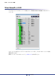
第6章 Tree Viewウィンドウ Tree ViewウィンドウではAmp Editorがモニター /コントロールできる機器の表示/追加/削除が できます。 ワークスペース、機器などが階層表示され、システム全体の構成を視覚的に確認することができま す。また、アイコンをダブルクリックすると、対応するDetail Viewウィンドウが表示されます。 Tree Viewウィンドウはメインパネルウィンドウの[Show/Hide Tree]ボタン( )をクリック するか、メニューの[View]→[Tree]を選択することで表示/非表示を切り替えます。 ワークスペース [+]/[−]ボタン ツリー ● すべて展開( ) ボタンをクリックするとツリー内の全階層を表示します。 ● すべて省略( ) ボタンをクリックするとツリー内の全階層を非表示にします。 Amp Editor 102 取扱説明書
第6章 Tree Viewウィンドウ ● [New Device]ボタン( ) ボタンをクリックすると、「Select New Device」ダイアログボックス(105ページ)が開きま す。 ● [Device Detail View]ボタン( ) ボタンをクリックすると、選択されているアンプのDevice Detail View(115ページ)が開きま す。 ● [Signal Path View]ボタン( ) ボタンをクリックすると、選択されているTXnのSignal Path Viewウィンドウ(144ページ)が 開きます。 ● [Device Properties]ボタン( ) ボタンをクリックすると、選択されているアンプのDevice Propertiesウィンドウ(127ページ) が開きます。 ● ワークスペース Amp Editorでモニター /コントロールする機器の集合です。 ● [+]/[−] ワークスペース、機器アイコンの左にある[+]/[−]ボタンで下の階層を表示/非表示します。下 の階層が表示されているときはボタンが[−]になり、クリックすると下の階層が表示
第6章 Tree Viewウィンドウ ツリー構成 I/Oカード 機器 AMP ID Unmatched Device ● 機器 Amp Editorに登録されている機器をアイコンと名称で表示します。 機器のアイコンの表示によって、オンライン状態やアラート発生などの状況がわかります。 表示 状態 ネットワーク上に存在しない、あるいはコンピューター (Amp Editor)と接続さ れていない。 ネットワーク上に存在し、Amp Editorと同期状態(オンライン状態)。 ネットワーク上に存在するが、Amp Editorと非同期状態(オフライン状態)。 Amp Editorと同期状態(オンライン状態)で、何らかのアラートが発生。 ● ID 機器のDevice IDを表示します。 ● Model 機器の機種名を表示します。 ● Identify [Identify]ボタンをクリックすると、ボタンが点灯し、該当する機器本体でインジケーターやディス プレイが点滅します。機器本体でIdentify操作をすると、該当する機器に対応した[Identify]ボタン が点灯します。表示/操作方法は機器によって異な
第6章 Tree Viewウィンドウ Tree Viewウィンドウでの操作 Tree Viewウィンドウではアイコンをダブルクリックしたり、右クリックしたり、ドラッグアンド ドロップすることで様々な操作ができます。 ■ 追加(New Device) ツリーに機器を追加することができます。 NOTE ・ 追加できるACD1は32台までです。 [New Device]ボタン 1. TXnやACD1を追加する場合はワークスペースのアイコンを、ACD1につなげるアンプを追 加する場合はつなげるACD1のアイコンを選択したあと[New Device]ボタンをクリックす るか、アイコンを右クリックして[New Device...
第6章 Tree Viewウィンドウ 2. [Device List]から追加する機器を選択して[Add]ボタンをクリックします。 右側の[Device]に選択した機器が追加されます。 NOTE ・ [Device List]に表示されている機器をダブルクリックすることでも機器が追加されます。 ・ [Add Range...]ボタンをクリックすると、同じ機種の機器を複数追加できます。 ・ 追加した機器のIDを変更する場合は、ID欄をクリックして変更するIDを選択してくださ い。 3. [OK]ボタンをクリックします。 ワークスペースの下に新規機器が追加されます。 ■ 設定のコピー (Copy) ツリー内のアンプの設定をコピーします。コピーにはDevice IDなどの機器固有の設定以外をコピー する[All current parameters]と、選択した設定をコピーする[Selected parameters]の2種類が あります。 ● All current parametersの場合 1. 設定をコピーしたいアンプのアイコンを右クリックします。 2.
第6章 Tree Viewウィンドウ ● Selected parametersの場合 1. 設定をコピーしたいアンプのアイコンを右クリックします。 2. コンテキストメニューで[Copy]→[Selected parameters...]を選択します。 「Select Copy Item」ダイアログボックスが開きます。 3. コピーする設定を選択します。 オフライン時、[Scene]チェックボックスにチェックを入れることで、シーンをコピー対象 にできます。 4. [OK]ボタンをクリックします。 選択した設定がコピーされます。 ■ 設定の貼り付け(Paste) コピーしたアンプの設定を同一シリーズのアンプにペーストします。 1. 設定を貼り付けたいアンプのアイコンを右クリックします。 2. コンテキストメニューで[Paste]を選択します。 3.
第6章 Tree Viewウィンドウ ■ 名称の変更(Rename Label) 機器やワークスペースの名称(ラベル)を変更することができます(I/Oカードを除く)。 1. 名称を変更したいアイテムのアイコンを右クリックします。 2. コンテキストメニューで[Rename Label]を選択します。 「Rename Label」ダイアログボックスが開きます。 NOTE ・ アンプ以外のアイテムではNameのみ変更できます。 3. [Device]や[Ch A]などの横のボックスに変更する名称を入力します。 4. [OK]ボタンをクリックします。 名称が変更され、ダイアログボックスが閉じます。[Cancel]ボタンをクリックした場合、名 称は変更されずにダイアログボックスが閉じます。 ■ Device IDの変更(Change Device ID)(XMV以外) 機器のDevice IDを変更することができます。 1. IDを変更したいアイテムのアイコンを右クリックします。 2.
第6章 Tree Viewウィンドウ ■ 解除(Disengage Device Matching) オフラインの機器をワークスペースから解除して、Unmatched Deviceに移動します。 NOTE ・ Unmatched Deviceに移動した機器は、ドラッグアンドドロップすることでワークスペースに移動 できます。 1. 解除したいアイテムのアイコンを右クリックします。 2. コンテキストメニューで[Disengage Device Matching]を選択します。 3. 確認ダイアログボックスの[OK]ボタンをクリックします。 アイテムが解除されて、Unmatched Deviceに移動します。 ■ 削除(Delete) オフラインの機器を削除することができます。 1. 削除したいアイテムのアイコンを右クリックします。 2. コンテキストメニューで[Delete]を選択します。 確認ダイアログボックスが開きます。 3.
第6章 Tree Viewウィンドウ ■ I/Oカード設定(MY Card Type) TXnに挿入されているI/Oカードをオフライン時に変更できます。TXnには標準でAES-IOカードが 挿入されています。 1. TXnのアイコンを右クリックします。 2. コンテキストメニューで[MY Card Type]を選択します。 「Select MY Card」ダイアログボックスが表示されます。 3. [Card]横のドロップダウンメニューから、該当するカードを選択します。カードを挿入しな い場合は「none」を選択します。 4.
第6章 Tree Viewウィンドウ ■ 機器の特定(Identify) [Identify]ボタンをクリックするか、機器のアイコンを右クリックして[Identify]を選択すると、該 当する機器本体でインジケーターやディスプレイが点滅します。 ■ 機器情報の表示(Device Information) 右クリックしてコンテキストメニューから[Device Information]を選択すると、 「Device Information」ダイアログボックスが開き、ワークスペース内の接続されている機器の情報を一覧表 示します。詳しくはメインパネルウィンドウの「Device Information」(49ページ)をご参照くだ さい。 ■ 機器の各種設定(Utility) 機器のアイコンを右クリックすると表示されるコンテキストメニューから[Utility...
第6章 Tree Viewウィンドウ ■ マッチング(Device Matching) 機器をネットワークに接続したとき、通常はAmp Editor上の機器と実際の機器が自動的に関連付け されます。Amp Editor上の機器と実際の機器でDevice IDやMACアドレスが異なる場合は、Amp Editor上の機器と実際の機器を手動で関連付け(マッチング)させる必要があります。故障などで機 器を入れ替えた場合にマッチングさせる必要があります。 NOTE ・ XMVはこの機能でマッチングできません。リアパネルの機器設定ディップスイッチと[UNIT ID] ロータリースイッチを組み合わせて、UNIT IDをマッチングさせてください。 1. Unmatched Deviceにある機器のアイコンを右クリックします。 2. コンテキストメニューで[Device Matching...]を選択します。 「Device Matching」ダイアログボックスが表示されます。 3.「Device」に表示されている機器からマッチングさせたいAmp Editor上の機器を選択しま す。 4.
第6章 Tree Viewウィンドウ ■ Unmatched Deviceからワークスペースへの移動(Move) Unmatched Deviceに表示されている機器をモニター /コントロールするためにはワークスペース に移動する必要があります。 NOTE ・ ドラッグアンドドロップでも移動できます。 1. Unmatched Deviceにある機器のアイコンを右クリックします。 2.
第7章 Detail Viewウィンドウ Detail Viewウィンドウでは、Tree Viewウィンドウで選択されたアイテムのモニター /コント ロールをします。 このウィンドウを呼び出すためには以下の方法があります。 ● Tree Viewウィンドウ内のアイコンをダブルクリックする。 アンプの場合はDevice Detail View、デジタルI/Oカードの場合はI/O Card Editorが表示されます。 ● Tree Viewウィンドウ内の機器を選択したあと、[Device Detail View]ボタン、[Signal Path View]ボタン、[Device Properties]ボタンをクリックする。 該当するウィンドウが表示されます。 ● Tree Viewウィンドウのアイコンを右クリックして、[Show]から表示するウィンドウを選択する。 該当するウィンドウが表示されます。 NOTE ・ Signal Path Viewは「Signal Path Viewウィンドウ」(144ページ)をご参照ください。 ・ Device Propertiesは「Device Propertiesウ
第7章 Detail Viewウィンドウ Device Detail View Device Detail Viewは選択されたアンプをモニター /コントロールします。 画面構成はアンプにより異なります。 TXnの場合 Tn/PC-Nの場合 Amp Editor 115 取扱説明書
第7章 Detail Viewウィンドウ XMの場合 XP/XHの場合 XMVの場合 以降この章では、TXnの画面イラストを使って説明します。 Amp Editor 116 取扱説明書
第7章 Detail Viewウィンドウ ■ Input部(TXn/Tn/PC-Nのみ) アンプへの入力をモニター /コントロールすることができます。Slot Input、Matrix Mixer Input、 Signal Chain Checkは、TXnのみです。 q w r e q 入力レベル警告表示 各チャンネルの入力レベルがしきい値を超えている(HIGH)かどうかを表示します。 Device Propertiesウィンドウの[Input Alert]タブ(135ページ)で設定した入力レベルのしき い値を超えると、入力レベル警告インジケーターの色が赤に変化します。 「Alert Setup」ダイアログボックス(55ページ)でアラートに設定してある場合、アラートイン ジケーターも点灯してログが記録されます。 入力レベル警告インジケーター アラートインジケーター しきい値以下: 緑 しきい値以下: 消灯 しきい値超過: 赤 しきい値超過: 点灯 設定が無効 灰 : w 入力レベルメーター 各チャンネルの入力レベルを表示します。 Analog Inputメーターの表示
第7章 Detail Viewウィンドウ r [ON]ボタン(TXnのみ) 各チャンネルの入力信号をオン/オフ(ミュート)します。このボタンはMatrix Mixerのインプッ トチャンネル[ON]/[OFF]ボタンと同じです。 ■ Speaker Output部 アンプからの出力をモニター /コントロールすることができます。 ・ XH200の電源Standby/Onを切り替えた場合、内部のリレー回路を切り替える影響で、Speaker Outputの各メーターが意図しない値を表示することがあります。 NOTE q w e r t q 出力警告表示 Device Propertiesウィンドウの[Output Alert]タブ(137ページ)で設定した出力値のしきい 値を上回る(HIGH)か下回る(LOW)と出力警告インジケーターの色が赤に変化します。 「Alert Setup」ダイアログボックスでアラートに設定してある場合、アラートインジケーターも 点灯してログが記録されます。 出力警告インジケーター アラートインジケーター 上限しきい値超過 : 赤 設定値以内 : 消灯 上限
第7章 Detail Viewウィンドウ e インピーダンスメーター (TXn/Tn/PC-Nのみ) 各チャンネルのスピーカー出力端子のインピーダンスを表示します。Device Propertiesウィン ドウの[Output Alert]タブインピーダンスの上限と下限のしきい値の設定を変更することができ ます。 NOTE ・ インピーダンスはアンプがスピーカーに流す電流から算出しています。スピーカーからある程 度の音量が出力されるまではメーターが振れません。 r パワーメーター (TXn/Tn/PC-Nのみ) 各チャンネルの出力電力を表示します。Device Propertiesウィンドウの[Output Alert]タブの 出力電力の上限しきい値の設定で、アラートを表示させる出力電力の値を変更することができま す。 NOTE ・ ACD1に接続されているアンプの場合、消費電力が以下条件のときはメーターが振れません。 PC9500N/PC9501N:0.50 W以下、PC4800N/PC4801N:0.24 W以下、 PC3300N/PC3301N:0.17 W以下、PC6501N:0.
第7章 Detail Viewウィンドウ ■ Attenuation部 各チャンネルの減衰量をモニター /コントロールできます。 q w r e q アッテネーター (TXn/Tn/PC-N/XMVのみ) 各チャンネルの減衰量をスライダーまたは数値入力でコントロールします。GRメーター (TXnの み)では、アンプ保護回路のリミッターによるゲインリダクション量を表示します。 w [LINK]ボタン(TXn/Tn/PC-Nのみ) アッテネーターの値をチャンネル同士で連動(リンク)させます。Bridgeモードのときはボタンが 無効です。 LINKオン: LINKオフ: [LINK]ボタンをクリックしてオンにするときは、プルダウンメニューからチャンネル間のオフ セット動作を選択します。 Absolute Link(Align to A) :チャンネルAの値をチャンネルBにコピーして、リンク動作します。 Absolute Link(Align to B) :チャンネルBの値をチャンネルAにコピーして、リンク動作します。 Relative Link :チャンネル間のオフセットを維持したまま、リンク動作
第7章 Detail Viewウィンドウ e [SOLO]ボタン(XMV以外) 各チャンネルのソロをオン/オフにします。 メインパネルウィンドウのソロ機能(Solo Master)がオンのときのみ、有効です。 ソロのモードが「Last」のときにオンにすると、ワークスペース内で最後に指定したチャンネル の信号だけがソロ出力されます。ソロのモードが「Mix」のときにオンにすると、ワークスペー ス内で指定した複数のチャンネルの信号がソロ出力されます。 r [MUTE]ボタン 各チャンネルの出力信号をミュートします。 ミュートオン: ミュートオフ: t [Polarity]ボタン(Tn/PC-N/XMVのみ) 各チャンネルの出力信号の位相反転を設定します。 反転オン : 反転オフ : このボタンはTn/PC-Nの場合のみです。TXn の場合はSignal Path Viewウィンドウで設定し ます。 Amp Editor 121 取扱説明書
第7章 Detail Viewウィンドウ ■ General部 アンプ全体に関わる設定をモニター /コントロールします。 t y u i q w r e o q 温度モニター (TXn/Tn/PC-Nのみ) アンプ部のヒートシンク温度を0%〜100%でメーター表示します。90%を超えると保護回路 が動作してスピーカー出力がミュートされるので、十分な余裕を持って運用してください。 NOTE ・ メーターにはアンプ部のヒートシンク温度のみ表示されます。電源部の温度は表示されませ ん。 ・ 90%の温度はアンプによって異なります。詳しくは各アンプの取扱説明書またはリファレンス マニュアルをご参照ください。 電源保護インジケーターは、電源部の状態を示し、アンプが持っている電源保護温度を超えると 赤色に変化します。「Alert Setup」ダイアログボックスでアラートに設定してある場合、アラー トインジケーターも点灯してログが記録されます。 電源保護インジケーター 正常時 アラートインジケーター : 緑 正常時 : 消灯 電源保護時 : 赤 電源保護時 : 点灯 アンプ保護イ
第7章 Detail Viewウィンドウ w ファンモニター (TXnのみ) 冷却用ファンの回転状態とファンスピードを表示します。 ファンスピードはファンの回転数を%単位で表示します。100%時のファンの回転数はアンプに よって異なります。 ファンが停止しているとファン回転インジケーターの色が赤に変化します。「Alert Setup」ダイ アログボックスでアラートに設定してある場合、アラートインジケーターも点灯してログが記録 されます。 ファン回転インジケーター アラートインジケーター 回転時 : 緑 回転時 : 消灯 停止時 : 赤 停止時 : 点灯 TXnのフロントパネルから見て左側のファンがFAN A、右側のファンがFAN Bです。 e アンププロテクト アンプの保護機能が動作したことを通知します。 Protection 以下のLimiter、Mute、Shutdownのいずれかの保護機能が動作したときにプロテクトイン ジケーターが赤色に変化します。このとき、TXn本体パネルのPROTECTIONインジケー ターも点灯します。 プロテクトインジケーター 正常時 アラートイン
第7章 Detail Viewウィンドウ Mute(TXnのみ) アンプ部のヒートシンクの温度指標が90%以上になったり、ショートして負荷が0.
第7章 Detail Viewウィンドウ t リダンダントモード(TXnのみ) アンプの入力リダンダンシーモード(Redundant Backup/Override/Off)を表示します。モード の変更はDevice Propertiesウィンドウの[General]タブで行ないます。 y Amp Mode(TXn/Tn/PC-N/XP/XMのみ) アンプの出力モード(Stereo/Parallel/Bridge)を表示します。モードの変更はDevice Propertiesウィンドウの[General]タブ(131ページ)で行ないます。 u Amp Gain/Sensitivity(TXnのみ) 各チャンネルのゲインと入力感度の値を表示します。設定の変更はDevice Propertiesウィンド ウの[General]タブで行ないます。 i [Device Properties]ボタン ボタンをクリックすると、Device Propertiesウィンドウ(127ページ)が開きます。 o Redundancy (XMV V3.
第7章 Detail Viewウィンドウ ■ その他 q w e r t q Scene シーン番号とシーンの名前を表示します。 w Amp Name アンプの名称を表示します。 e [SLOT OUT]ボタン(TXnのみ) ボタンをクリックすると、「Slot Output」ウィンドウが開きます。 「Slot Output」ウィンドウではスロット出力のレベルと出力警告インジケーターの状態をモニ ターできます。 r [Signal Path View]ボタン(TXnのみ) ボタンをクリックするとSignal Path Viewウィンドウ(144ページ)が開きます。 t [STANDBY]/[ON]ボタン アンプの電源の状態(Standby/On)をモニター /コントロールします。 [STANDBY]/[ON]ボタンクリックすると、電源Standby/Onを切り替えできます。 NOTE On時 ・ XM/XP/XH以外のアンプをオンライン中にStandbyからOnに切り換えると、機器の電源がOn になるまでボタンが黄色点滅します。 : Standby時 : Amp Editor 126
第8章 Device Propertiesウィンドウ パワーアンプの出力モード、ゲイン/入力感度、アラート/プロテクションなどの各種設定を行ない ます。 [Device Properties]ボタン( )をクリックするか、Tree Viewウィンドウのアンプのアイ コンを右クリックしてコンテキストメニューから[Show]→[Device Properties]を選択すると、 Device Propertiesウィンドウが表示されます。 ■ [Input (−V3.0)]タブ(XMV) ファームウェアがV3.0以前のXMV用のタブです。 q w q Input Source 入力をアナログにするかデジタル(YDIFまたはDante)にするかを選択します。 w Digital Input Sensitivity デジタル入力の感度を設定します。XMVのファームウェアがV1.
第8章 Device Propertiesウィンドウ ■ [Input (V3.1−)]タブ(XMV) ファームウェアがV3.
第8章 Device Propertiesウィンドウ w Input Redundancy アナログ入力信号とデジタル入力信号の両方を使い、オーディオ入力回線を二重化できます。 モード名 内容 Off リダンダンシー機能オフ Redundant Backup デジタル入力信号をメインとし、デジタル入力のパイロットトーンが途切 れると、アナログ入力信号に自動で切り替わります。 Redundant Override デジタル入力信号をメインとし、指定レベル以上のアナログ入力信号を検 出すると、アナログ端子からの入力信号に自動で切り替わります。 切り替えのレベルは、Override欄のOverride Thresholdで指定します。 Auto Return チェックすると、自動で復帰します。 Redundant Backup: デジタル入力のパイロットトーンを検出したら、デジタル入力 に復帰します。 Redundant Override:アナログ入力信号がしきい値を下回ったら、デジタル入力に切 り替わります。 チャンネル選択 設定するアンプチャンネルを選択します。 Redundanc
第8章 Device Propertiesウィンドウ ■ [General]タブ(XMV以外) アンプの出力モードなどの各種モードを設定します。オンライン/オフライン時に設定を変更できま す。XMVについては132ページをご参照ください。 w q e q Input Redundancy(TXnのみ) アナログ入力信号とデジタル(スロット)入力信号の両方をリダンダンシー接続(オーディオ接続の 2重化)できます。断線などのトラブルでデジタル入力音声が途切れた場合にアナログ入力に切り 替えたり(Redundant Backup)、アナログ入力音声を検出した場合だけアナログ入力に切り替え たり(Redundant Override)できます。 Redundant Mode リダンダンシー接続のモードを設定します。設定は以下の3種類です。 モード名 内容 Off リダンダンシー接続オフ Redundant Backup スロットに装着したカードからの入力信号をメインとし、カードからの入力 がアンロックになると、アナログ端子からの入力信号に自動で切り替わりま す。お使いのI/OカードがRedund
第8章 Device Propertiesウィンドウ Override Threshold Redundant Overrideモードの場合、アナログ入力の有無を判定するための入力レベルのし きい値をチャンネルごとに設定します。 Auto Return Delay Redundant OverrideモードでAuto ReturnがONの場合、アナログ入力が途切れたと判定 してからデジタル入力に切り替えるまでの時間を設定します。 Auto Return Redundant Backupモードの場合、途切れていたスロット入力が復帰したときにスロット入 力を有効に戻すかどうかを設定します。 Redundant Overrideモードの場合、アナログ入力が途切れたときにスロット入力を有効に 戻すかどうかを設定します。 w Amp Mode(TXn/Tn/PC-N/XP/XMのみ) アンプの出力モード(Stereo/Bridge/Parallel)を表示(TXnの場合は設定)します。 出力モードの詳細については、各アンプの取扱説明書をご参照ください。 NOTE ・ TXnの場合は、ここで出力モードを設
第8章 Device Propertiesウィンドウ ■ [General]タブ(XMV) ディップスイッチ設定の表示や各チャンネルの周波数の設定をします。オンライン時のみ設定を変更 できます。 q w q Output Setup XMVのリアパネルにある[SPEAKERS]ディップスイッチの設定を表示します。 NOTE ・ XMVのリアパネルにある[SPEAKERS]ディップスイッチが決められた組み合わせ以外になっ ている場合やオフライン時は、「---」と表示します。[SPEAKERS]ディップスイッチの詳細は XMVの取扱説明書をご参照ください。 w HPF HPFの周波数を設定します。ハイインピーダンス時は40Hz/80Hz、ローインピーダンス時は Off/40Hz/80Hzが選択できます。 NOTE ・ XMVのリアパネルにある[SPEAKERS]ディップスイッチが決められた組み合わせ以外になっ ている場合やオフライン時は、「---」と表示します。 Amp Editor 132 取扱説明書
第8章 Device Propertiesウィンドウ ■ [Limiter]タブ(TXnのみ) 各アンプのリミッターの値を設定します。 オンライン/オフライン時に設定を変更できます。 q r w t e q Voltage Limiter 出力電圧によるリミッターの設定をします。 チェックボックス リミッターのOn/Off を設定します。 Threshold 出力電圧の上限しきい値を設定します。 [←APPLY]ボタンをクリックすると、「Calculate the Output Voltage」で計算した値が 設定されます。 Attack しきい値を超えたときに20dB減衰させるのにかかる時間を設定します。 Release しきい値以下に戻ったときに、減衰させていた電圧を元のレベルに戻すまでにかかる時間を設 定します。 Amp Editor 133 取扱説明書
第8章 Device Propertiesウィンドウ w Power Limiter 出力電力によるリミッターの設定をします。 チェックボックス リミッターのOn/Off を設定します。 Threshold 出力電力の上限しきい値を設定します。 e Limiter Gain Reduction Limiterのチャンネル連動のOn/Off を設定します。 「On」のとき、片方のチャンネルにリミッターがかかると、もう片方のチャンネルも連動して動 作します。 r Output Voltage Calculator Voltage LimiterのThresholdに設定する値を計算します。 Output Power アンプの出力電力を入力します。 Load Impedance 各チャンネルに接続されたスピーカーのインピーダンスを入力します。 [=]ボタン ボタンをクリックすると、PowerとImpedanceに入力された値を基に出力電圧を計算しま す。 t [←APPLY]ボタン ボタンをクリックすると、Output Voltage CalculatorのOutput Voltageの値をボタン
第8章 Device Propertiesウィンドウ ■ [Input Alert]タブ(TXn/Tn/PC-Nのみ) アンプの最大入力のしきい値などの設定をします。オンライン/オフライン時に設定を変更できま す。 w q e r Analog Input Voltage、Slot Input Voltage(TXnのみ)とMatrix Mixer Input Level(TXnのみ) での設定内容は同じです。 q チャンネルチェックボックス アラート検出の有効/無効を設定します。設定した時間内(Detection Time)に、設定したしきい 値(Threshold)を超えているポイントを、設定した回数(Count)検出した場合、アラートと判断 します。検出は2ms間隔です。 w Threshold 最大入力レベルのしきい値を設定します。 e Detection Time(TXnのみ) しきい値を超えているポイントをカウントする有効期間を設定します。 Amp Editor 135 取扱説明書
第8章 Device Propertiesウィンドウ r Count(TXnのみ) しきい値を超えているポイントを何回検出したらアラートと判定するかを設定します。 アラート検出のパラメーター 値 = Count Threshold Detection Time 時間 現在 Amp Editor 136 取扱説明書
第8章 Device Propertiesウィンドウ ■ [Output Alert]タブ アンプの最大出力に関するしきい値などの設定をします。オンライン/オフライン時に設定を変更で きます。インピーダンスを設定することで、パイロットトーンを使わないで出力が断線またはショー トしていないかどうかの検出ができます。 NOTE ・ [Calibration by Program Source...]ボタンはオンライン時のみ有効になります。 ・ パイロットトーンを使った出力の断線またはショートの検出については[Output Signal Chain Check]タブ(140ページ)で設定します。 q w e y r t Speaker OutputとSlot Output Level(TXnのみ)での設定内容は共通です。 q [Calibration by Program Source...
第8章 Device Propertiesウィンドウ e Threshold 最大出力のしきい値を設定します。 r Detection Time(TXnのみ) しきい値を超えているポイントをカウントする有効期間を設定します。 t Count(TXnのみ) しきい値を超えているポイントを何回検出したらアラートと判定するかを設定します。 y Thermal アンプ部の温度上限しきい値を設定します。 ●「Calibration by Program Source」ダイアログボックス パイロットトーン以外のオーディオ信号(Program Source)の出力を用いて各チャンネルに接続 されたスピーカーのインピーダンス値を計測し、[Output Alert]タブの対応するSpeaker OutputのImpedance MaxとImpedance Minの値を設定します。 NOTE ・ 測定が完了するまでに10秒程度かかります。 ・ Program Sourceの特性によっては、正しく測定ができない場合があります。 ・ Program Sourceのレベルが小さいと、正しく測定ができない場合があります。 ・ アッ
第8章 Device Propertiesウィンドウ ■ [Input Signal Chain Check]タブ(TXnのみ) 外部機器から供給されるパイロットトーンを検出して入力が断線などで途切れていないかどうかの判 断するための設定をします。オンライン/オフライン時に設定を変更できます。 q w e r t y Analog InputとSlot Inputでの設定内容は共通です。 q Frequency パイロットトーンの中心周波数を設定します。 w [Monitoring the Pilot Tone]チェックボックス 入力が途切れたかどうかの監視を有効/無効にします。チェックされている場合、Detection Timeで設定した時間内に、Detection Thresholdで設定したレベル以上のパイロットトーンが 検出できなかったときに、Signal Chain Checkの警告インジケーターを赤色に点灯します。 e Detection Threshold パイロットトーン入力レベルのしきい値を設定します。 r Detected Level 受信した現在のパイロットトーンの入力レベルを表示
第8章 Device Propertiesウィンドウ y Notch Filter パイロットトーンの周波数成分を除去し、アンプからパイロットトーンを出力しないためのノッ チフィルターを設定します。ノッチフィルターの中心周波数はqFrequencyで設定した値となり ます。 チェックボックス ノッチフィルターの有効/無効を設定します。 Q ノッチフィルターの周波数帯域の幅を設定します。 ■ [Output Signal Chain Check]タブ(TXnのみ) パイロットトーンを使って出力が断線またはショートしていないかどうかの判定のための設定をしま す。パイロットトーンを出力することにより、音声信号出力に依存せず安定してインピーダンスを検 出できます。 オンライン/オフライン時に設定を変更できます。 q w e 注意 ・ 接続しているスピーカーにHFドライバーが搭載されている場合は、Low Frequencyのチェックは入れないで ください。パイロットトーンはSpeaker Processorの後ろで追加されるため、低周波成分でドライバーを破 損させる恐れがあります。 Channel
第8章 Device Propertiesウィンドウ q [Calibration by Pilot Tone...]ボタン このボタンをクリックすると、「Calibration by Pilot Tone」ダイアログボックス(142ページ) が開きます。 「Calibration by Pilot Tone」ダイアログボックスではパイロットトーンを使って[Output Signal Chain Check]タブのDetection Interval Time以外の値を設定します。 NOTE ・ [Calibration by Pilot Tone...
第8章 Device Propertiesウィンドウ ●「Calibration by Pilot Tone」ダイアログボックス パイロットトーンを用いて各チャンネルに接続されたスピーカーのインピーダンス値と検出レベ ルの下限しきい値を計測し、[Output Signal Chain Check]タブのDetection Interval Time 以外の設定します。 ・ 測定が完了するまでに最大120秒程度かかる場合があります。 NOTE ・ スピーカーから超低音や超高音が出力されますのでご注意ください。 ・ スピーカーの特性によっては、正しく測定ができない場合があります。 ・ アッテネーターで出力を下げていると、正しく測定ができない場合があります。 q w e r t q [Frequency Type] パイロットトーンの低周波成分(5Hzまたは10Hz)と高周波成分(20kHz)の組み合わせを設定し ます。通常は「10Hz(Low) & 20kHz(High)」の組み合わせを選択してください。 w チェックボックス 各チャンネルに出力するパイロットトーンの周波成分を設定します。接続してい
第8章 Device Propertiesウィンドウ e [Calibration Start]ボタン ボタンをクリックすると、各チャンネルに接続されたスピーカーのインピーダンス値とレベルの 下限しきい値の計測を開始します。 r「Result」 計測結果と、その値から計算されたThresholdの推奨値を表示します。 Detection Threshold Level : 検出したレベルより3 dB低い値 Impedance Threshold Max : 検出したインピーダンスの2倍 Impedance Threshold Min : 検出したインピーダンスの半分 NOTE ・ 正常な結果が一つもない場合、グレー表示となります。 t [OK]ボタン 設定した項目と計測されたレベルとインピーダンスを基に「Output Signal Check」タブの Detection Interval Time以外の対応する項目の値を設定します。 Amp Editor 143 取扱説明書
第9章 Signal Path Viewウィンドウ (TXnのみ) Signal Path Viewウィンドウには、TXnの内蔵DSPによる音声信号処理機能がモジュール化され たコンポーネントとして信号経路上に配置されています。 このウィンドウを呼び出すためには以下の方法があります。 ● Detail Viewウィンドウ内の[Signal Path View]ボタンをクリックする。 ● Tree Viewウィンドウ内のTXnを選択したあと、[Signal Path View]ボタンをクリックする。 ● Tree Viewウィンドウのアイコンを右クリックして、[Show]→[Signal Path View]選択する。 NOTE ・ Input RedundancyモードやPower Ampモードの設定によって、信号経路の表示が変化します。 ・ Gain/Sens.
第9章 Signal Path Viewウィンドウ(TXnのみ) コンポーネントエディターを開く コンポーネントのアイコンをクリックすると、該当するコンポーネントエディターのウィンドウが開 きます(146ページ)。コンポーネントの詳細なパラメーターは、コンポーネントエディター上で編 集します。 クリック 機能や信号のオン/オフを切り替える 各コンポーネントや信号経路上に表示されている[ON]ボタンまたは[MUTE]ボタンをクリックする と、各コンポーネントの機能やミュートのオン/オフを切り替えられます。 クリック NOTE ・ クリックしても何も起こらない箇所は、表示だけの機能です。 Amp Editor 145 取扱説明書
第10章 コンポーネントエディター (TXnのみ) Signal Path Viewウィンドウに配置されているコンポーネントをクリックすると、コンポーネン トエディターウィンドウが開きます。コンポーネントエディターでは、コンポーネントのパラメー ターを詳細に編集します。 各部の名称と機能 タイトルバー Snap エディットボックス ノブ ボタン NOTE ・ コンポーネントの種類によって、内容もタイトルバーに表示される名前も異なるウィンドウが開き ます。 ● タイトルバー コンポーネント名が表示されます。 ● Snap(スナップ) コンポーネントエディターのパラメーターセットを4つまで一時的に記憶できます(153ページ)。 ボタンをクリックすると、パラメーターセットを切り替えます。各ボタンをドラッグして他のボ タンにドロップすると、パラメーターセットをコピーできます。ボタンを右クリックすると表示 されるコンテキストメニューからもコピーできます。 ● ノブ ドラッグしてパラメーターを変更します。「Preferences」ダイアログボックスの[Component Editor]タブ→[Knob
第10章 コンポーネントエディター (TXnのみ) ● スライダー つまみをドラッグしてパラメーターを変更します。バーに対するマウス操作の動作は、 「Preferences」ダイアログボックスの[Component Editor] タブ→[Slider Mode]で設定しま す(39ページ)。 つまみ バー NOTE ・ 詳細な設定をするには、キーを押しながらドラッグします。キーを押しながら クリックすると初期値にリセットされます。 ● ボタン ボタンにはいくつかの種類があります。 オン/オフを切り替えます。オンになると点灯します。機能によって色分けされています。 オンのとき オフのとき 複数のボタンがセットになっていて、1つを選択すると別のボタンがオフになります。 オンのとき オフのとき 別のウィンドウが開きます。カスタムコントロールパネルには配置できません。 Amp Editor 147 取扱説明書
第10章 コンポーネントエディター (TXnのみ) ● プルダウンメニュー クリックすると、プルダウンメニューが表示されます。 ● エディットボックス 現在の設定値が表示されます。マウス操作やキーボードからの入力で値を変更します。値を変更 すると、ノブやスライダーが動きます。 クリック 選択されたエディットボックスは、文字が赤くなります。キーボードから入力して、値を変更 できます。キーを押すと入力が確定します。 スピンボックスでの値変更 マウスカーソルをエディットボックスに合わせるとスピンボックスが表示されます。 [▲]/[▼]ボタンをクリックすると値が増減します。 クリック Amp Editor 148 取扱説明書
第10章 コンポーネントエディター (TXnのみ) ダブルクリック 数値が選択されます。キーボードから入力して、値を変更できます。キーを押すと 入力が確定します。 キーボードから入力 キーで確定 キーでの移動 エディットボックスが選択されている状態でキーを押すと、次のエディットボックス が選択されます。+キーを押すと、前のエディットボックスが選択されま す。 キー /マウスでの値変更 選択されているエディットボックスはキーとマウスで値を変更できます。 ・ 上下の方向キー 数値を増減させます。 ・ キー /キー 数値を大きく増減させます。 ・ キー キーを押すと値が確定します。 ・ キー+キー +キーを押すと、初期値にリセットされます。 ・ マウスホイール マウスカーソルがエディットボックス上にある場合、マウスホイールを回すと数値が増減 します。 ・ ドラッグ 上下方向または左右方向にドラッグすると、数値
第10章 コンポーネントエディター (TXnのみ) ● グラフ パラメーターをグラフィカルに表示します。パラメーターを変更すると、グラフの形が変わりま す。 コントロールポイントのあるグラフは、ドラッグして、パラメーターを変更できます。ドラッグ の方向が上下または左右に限定されるコントロールポイントは、コントロールポイントにマウス カーソルを合わせ、マウスボタンを押したままにするとマウスカーソルの形が双方向矢印に変わ ります。矢印の向きにドラッグすると、パラメーターが変わります。 ドラッグの方向が限定されないコントロールポイントは、通常、コンポーネントエディター内の 複数のパラメーターによって位置が決定します。ドラッグする向きによっては、複数のパラメー ターが変化します。 グラフの中に複数のコントロールポイントがある場合は、色分けされています。対応するノブや エディットボックスの下にコントロールポイントと同じ色のバーがあります。 マウス カーソル コントロール ポイント NOTE ・ コントロールポイントのあるグラフをカスタムコントロールパネルにコピーしても、コント ロールポイントは表示されません
第10章 コンポーネントエディター (TXnのみ) オペレーションモードとデザインモード コンポーネントエディターとカスタムコントロールパネル(179ページ)には、「オペレーションモー ド」と「デザインモード」があります。オペレーションモードでパラメーターを変更し、デザイン モードでカスタムコントロールパネルに操作子をレイアウトします。 オペレーションモードとデザインモードは、コンポーネントエディター /カスタムコントロールパネ ルのウィンドウ内を右クリックすると表示されるコンテキストメニューで切り替えます。[Design Mode]でデザインモードをオン/オフします。デザインモードになっているときはチェックマークが つきます。チェックマークがついているときに選択するとデザインモードがオフになり、オペレー ションモードに戻ります。 オペレーションモード デザインモード NOTE ・ コンポーネントエディターでは、カスタムコントロールパネルにコピーするために、操作子を選択 できます。+クリックで複数の操作子を選択できます。 Amp Editor 151 取扱説明書
第10章 コンポーネントエディター (TXnのみ) コンテキストメニュー ウィンドウ内で右クリックすると表示されるコンテキストメニューは、オペレーションモードとデザ インモードで異なります。また、コンポーネントエディターとカスタムコントロールパネルでも異な り、クリックする位置によっても異なります。 ■ オペレーションモードのコンテキストメニュー オペレーションモードのコンテキストメニューに表示されるコマンドの一部は、デザインモードでも 表示されます。 ● [Design Mode] デザインモードとオペレーションモードを切り替えます。デザインモードになっているときは、 コマンド名の左のチェックマークがつきます。 ● [Peak Hold] レベルメーターのピークホールドのオン/オフとリセットします。 [On] 選択するとチェックマークがつき、ピークホールドがオンになります。チェックマークがつい ているときに選択すると、オフになります。 ピークホールドのオン/オフはAmp Editor上だけで有効な設定です。 [Reset] ピークホールドをリセットします。 NOTE ・ ピークホールドは
第10章 コンポーネントエディター (TXnのみ) ● [Close All Editor Windows] すべてのエディターウィンドウを閉じます。 ● [Device Properties...
第10章 コンポーネントエディター (TXnのみ) ● エディター起動時とは異なるパラメーターセットが記憶されているボタン パラメーターセットが変更されているボタンは、ボタン名の色が変わります。ボタンを選択する と点灯します。 NOTE ・ シンプルなコンポーネントやSpeaker Processorに含まれるコンポーネントには、スナップボ タンはありません。 ■ パラメーターセットの記憶 ● スナップボタンの切り替え スナップボタンを切り替えたときのパラメーターが、切り替える前のスナップボタンに記憶され ます。 1. パラメーターセットを記憶させるスナップボタン([A]〜[D])をクリックしてオンにします。 2. エディター内のパラメーターを記憶させる状態にセットします。 3. ほかのスナップボタンをクリックします。 ● ライブラリーのリコール(Speaker Processorのみ) 1. パラメーターセットを記憶させるスナップボタンをクリックしてオンにします。 2.
第10章 コンポーネントエディター (TXnのみ) ライブラリー Speaker Processorコンポーネントや8 Band EQコンポーネントのパラメーターセットをライブ ラリーアイテム(ファイル)として保存します。保存したライブラリーアイテムを読み込むと、それぞ れのコンポーネントのパラメーターすべてが保存したときの状態にセットされます。ライブラリーア イテムの保存を「ストア」、読み込みを「リコール」と呼びます。 ライブラリーファイルはUser Libraryフォルダーで一括管理しています。User Libraryフォルダー に保存することで、プロジェクト保存時にライブラリーファイルをプロジェクトフォルダーにコピー できます(13ページ)。 NOTE ・ User Libraryフォルダーは「Properties」ダイアログボックスで設定できます(39ページ)。 ■ Speaker Processorコンポーネントライブラリー Library [RECALL]メニュー Library [RECALL]ボタン Library [STORE]ボタン ライブラリーファイルの拡張子は「.
第10章 コンポーネントエディター (TXnのみ) ■ リミッターのスレッショルドについて ヤマハが提供しているDMEライブラリーは、最大出力レベルが+24dBuであるDME24Nや SP2060などのプロセッサーと26dBゲインのパワーアンプの組み合わせを想定しています。 DMEライブラリーファイルをリコールするときに、Txnに最適化するために、リミッターのスレッ ショルドを+6dB上げています。またストアするときには-6dB下げています。 上記組み合わせ以外の場合は、Speaker ProcessorのLimiter(175ページ)でスレッショルドをさ らに以下のように変更してください。 ・ ゲインが6dB低い設定(最大出力が+18dBuのMY8-DA96に26dBゲインのアンプを組み合 わせていた場合など) → スレッショルドを6dB下げてください。 ・ ゲインが6dB高い設定(最大出力が+24dBuのSP2060と32dBゲインのアンプを組み合わせ ていた場合など) → スレッショルドを6dB上げてください。 ■ 8 Band EQコンポーネントライブラリー ライブラリーファイルの拡張子は、「
第10章 コンポーネントエディター (TXnのみ) ■ ライブラリーアイテムのストア コンポーネントのパラメーターセットをライブラリーファイルに保存します。 1. コンポーネントエディターのパラメーターをセットします。 2. コンポーネントエディターのLibrary [STORE]ボタンをクリックします。 「Store」ダイアログボックスが表示されます。 Speaker Processorコンポーネントの場合 4 3 6 5 3. ファイル名を入力します。 ファイル名がそのままライブラリー名になります。 NOTE 4. ・ Speaker Processorコンポーネントの場合は、ライブラリー名がTXn本体ディスプレイに表 示されます。TXn本体ディスプレイで表示できるライブラリー名の言語は英語のみで、20 文字までです。 ファイルを保存するフォルダーを指定します。 Library [RECALL]メニューに表示するには、フォルダーを変更せずに保存します。 NOTE 5.
第10章 コンポーネントエディター (TXnのみ) ■ ライブラリーアイテムのリコール ストアしたパラメーターセットをコンポーネントに読み込みます。Library[RECALL]ボタンでライ ブラリーアイテムをリコールします。ライブラリーアイテムをリコールすると、選択されているス ナップボタンにパラメーターセットが記憶されます。 1. パラメーターセットを記憶するスナップボタン([A]〜[D])をクリックします。 2. Library [RECALL]ボタンをクリックします。 Library [RECALL]メニューとして、User Libraryフォルダーのライブラリーアイテム、プ ロジェクトのフォルダーのライブラリーアイテム、プリインストールされているライブラ リーアイテムが表示されます。 Speaker Processorコンポーネントの場合 3.
第10章 コンポーネントエディター (TXnのみ) パラメーターリンク/コンポーネントリンク ■ パラメーターリンク/コンポーネントリンクとは 同種のパラメーター (コンポーネントの操作子)をグループにして、パラメーターをリンクできます。 これを「パラメーターリンク」と呼びます。パラメーターリンクグループに含まれるパラメーターの 1つを変更すると、同じパラメーターリンクグループのパラメーターが同様に変化します。 パラメーターリンクと同様に、同種のコンポーネントをグループにして、コンポーネント単位でパラ メーターをリンクできます。これを「コンポーネントリンク」と呼びます。 パラメーターリンク/コンポーネントリンクには、それぞれグローバルリンクとローカルリンクの2 種類があります(パラメーターリンク/コンポーネントリンクと組み合わせると、合わせて4種類に なります)。グローバルリンクはワークスペース内のアンプのパラメーター /コンポーネント、ロー カルリンクは1台のアンプに含まれるパラメーター /コンポーネントをリンクします。グローバルリ ンクはAmp Editor上だけで有効なリンクで、ローカルリンクはアン
第10章 コンポーネントエディター (TXnのみ) ■ パラメーターリンク対応リスト グローバルリンク(Absolute Linkのみ) ローカルリンク コンポーネントリンク パラメーターリンク コンポーネントリンク パラメーターリンク Attenuation ― ○ ― △* Output Mute ― ○ ― ― Speaker Processor 8Band EQ ○ ― ○ (Absolute Linkのみ) ― 4×4 Matrix Mixer Polarity Input Delay Oscillator ○ ○ ○ ○ その他 ― ― ― ― * Detail Viewウィンドウの[LINK]ボタンによるチャンネルA/B間のリンクのみ可能で、ローカルパラメーター リンクのグループに追加することはできません。 NOTE ・ パラメーター /コンポーネントは、複数のリンクグループに属することはできません。 ・ コンポーネントリンクのグループ作成およびグループへのコンポーネントの追加は、Signal Path Viewウィンドウで行
第10章 コンポーネントエディター (TXnのみ) ■ パラメーターリンクの作成 コンポーネントエディターおよびカスタムコントロールパネルで操作子を右クリックすると、コンテ キストメニューが表示されます。[Add Parameter to Parameter Link]→[Global Link]/[Local Link]→[Add Group]は、新しいグループを作成し、右クリックした操作子をグループに追加しま す。 同様に、Signal Path Viewウィンドウでコンポーネントを右クリックすると、コンテキストメ ニューが表示されます。[Add Component to Component Link]→[Global Link]/[Local Link]→ [Add Group]は、新しいグループを作成し、コンポーネントをグループに追加します。 ■ リンクグループへのパラメーター /コンポーネントの追加 コンポーネントエディターおよびカスタムコントロールパネルで操作子を右クリックすると、コンテ キストメニューが表示されます。[Add Parameter to Parameter Link]のサブメ
第10章 コンポーネントエディター (TXnのみ) ● ローカルリンク [Local Link]のサブメニューには、ローカルリンクのグループ名が表示されます。グループ名を クリックすると、パラメーター /コンポーネントがグループに追加されます。 NOTE ・ ローカルリンクが設定されているパラメーター /コンポーネントをグローバルリンクにも設定 する場合は、同じローカルリンク内の複数のパラメーター /コンポーネントをグローバルリン クに設定しないでください。予期せぬ動作になる可能性があります。 ローカルリンク ローカルリンク B A C D ローカルリンク ● 複数の操作子の追加 デザインモードでは、キーを押しながらクリックすることで、複数の操作子を選択でき ます。複数の操作子を選択しておくと、同時に複数のパラメーターをグループに追加できます。 Amp Editor 162 取扱説明書
第10章 コンポーネントエディター (TXnのみ) ■「Parameter Link」ダイアログボックス パラメーターリンク/コンポーネントリンクの状態を確認したり、編集したりします。 メインパネルウィンドウの[System]メニューの[Parameter Link]をクリックすると、 「Parameter Link」ダイアログボックスが表示されます。コンポーネントエディターやカスタムコ ントロールパネルのコンテキストメニューから[Open Parameter Link]を選択して表示することも できます。 リンクグループリスト ● [Global Parameter Link]/[Local Parameter Link]/[Global Component Link]/[Local Component Link]ボタン ウィンドウの表示を切り替えます。 Global Parameter Link ワークスペース内にある複数のアンプのパラメーターに対してリンクします。 Local Parameter Link 1台のアンプのパラメーターに対してリンクします。 Global Compone
第10章 コンポーネントエディター (TXnのみ) ● リンクグループリスト リンクグループのリストが表示されます。リンクグループとグループに属するパラメーター /コ ンポーネント/アンプが階層表示されます。 クリックすると、リンクグループに属するパラメーター /コンポーネント/アンプが選択されま す。 リンクグループ名 リンクグループ名の左の[+]/[−]をクリックすると、リンクグループの下層を表示/非表示し ます。 リンクグループ名を選択し、キーを押すと、リンクグループが削除されます。リン クグループ名を右クリックすると表示されるコンテキストメニューの[Delete]でも削除でき ます。 アンプアイコン リンクグループに属するパラメーター /コンポーネントを含むアンプが表示されます。アンプ アイコンの[+]/[−]でコンポーネントを表示/非表示、コンポーネントの[+]/[−]でパラ メーター、Min(最小値)、Max(最大値)を表示します。 アンプ/コンポーネント/パラメーターを右クリックすると表示されるコンテキストメニュー で、選択したアイテムをリンクグループから削除すること
第10章 コンポーネントエディター (TXnのみ) コンポーネントガイド ■ Slot Input Gain スロット入力の各チャンネル(1〜16)のゲインを-24〜+24dBの範囲で設定します。 スロット入力とアナログ入力のレベルを合わせるために使用します。 NOTE ・ Input Router(166ページ)のSnapと連動しています。Snapを切り換えるとゲインもそのSnapでの 設定値に切り替わります。 Amp Editor 165 取扱説明書
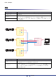
第10章 コンポーネントエディター (TXnのみ) ■ Input Router/Output Router(ルーター ) Input Routerはスロット入力(チャンネル1〜16)からアンプ入力(チャンネル1〜2)へのルーティ ング、Output Routerは出力ポイント(チャンネル1〜8)からスロット出力(チャンネル1〜16)へ のルーティングを設定します。 1つの出力には1つの入力のみ割り当てることができます。1つの入力を複数のチャンネルに出力で きますが、複数の入力を1つのチャンネルには出力できません。つまり、分配はできますが、ミキシ ングはできません。 NOTE ・ Output Routerへの入力には4種類の出力ポイントがあります。出力ポイントについて詳しくは、 「Signal Path Viewウィンドウ」(144ページ)をご参照ください。 Amp Editor 166 取扱説明書
第10章 コンポーネントエディター (TXnのみ) ● ルーティングの設定 入力チャンネルと出力チャンネルが交差する位置でクリックして、割り当てを変更します。セル にカーソルを合わせると、入出力チャンネルがハイライトして、青色の線が表示されます。ク リックすると、その位置のルーティングが設定されます。クリックした入力チャンネルに別の出 力チャンネルが割り当てられていた場合は、元の割り当ては解除されません。クリックした出力 チャンネルに別の入力チャンネルが割り当てられていた場合は、元の割り当ては解除されます。 クリック 別の入力チャンネルは解除 ● ルーティングの解除 ルーティングを示す「●」をクリックすると、ルーティングが解除されて「●」が消えます。 クリック ■ Polarity(位相反転) 信号の位相反転を設定します。ボタンをオンにすると、位相が反転します。 Amp Editor 167 取扱説明書
第10章 コンポーネントエディター (TXnのみ) ■ 4×4 Matrix Mixer(マトリクスミキサー ) 入力チャンネルと出力バスをマトリクス状に配置した4入力4出力のミキサーです。入力チャンネル ごとに独立してバランスを調整します。 縦に入力チャンネル、横に出力チャンネルが並んでいます。各入力チャンネルから各出力バスへのオ ン/オフを設定します。 q セクション パラメーター w 設定範囲 機能 q Input Master Level -∞〜+10dB 各入力チャンネルのレベルを設定します。 w Cross Point ON On/Off 各クロスポイントへのミックスのオン/オフを設定 します。 Amp Editor 168 取扱説明書
第10章 コンポーネントエディター (TXnのみ) ■ 8 Band EQ/6 Band EQ(パラメトリックイコライザー ) 指定した周波数の信号をブースト/カットするパラメトリックイコライザーです。入力部には8バン ドイコライザー、Speaker Processor部には6バンドイコライザーがあります。 NOTE ・「.
第10章 コンポーネントエディター (TXnのみ) パラメーター 設定範囲 機能 q Library[STORE] ― イコライザーのライブラリーをストアします。 ファイルの拡張子は「.ce2」です。 w Library[RECALL] ― イコライザーのライブラリーをリコールします。 ファイルの拡張子は「.ce2」または「.cel」です。 e PEQ特性 ― イコライザーの効果をグラフに表示します。 コントロールポイントをドラッグしてパラメーターを 変更します。 r Type PEQ, L.SHELF 6dB/Oct, L.SHELF 12dB/Oct, H.SHELF 6dB/Oct, H.SHELF 12dB/Oct, HPF, LPF, APF 1st, APF 2nd, Horn EQ t Q 0.1〜63.0 各周波数帯域の幅を設定します。 y Freq.
第10章 コンポーネントエディター (TXnのみ) APF(All Pass Filter) すべての周波数範囲の信号を通過させ位相だけを変化させるフィルターです。主にクロスオー バー帯域での位相整合のために使用します。APF 1stでは、設定した周波数において位相が 90°回転し、全帯域で見ると0°から180°まで回転します。APF 2stでは、設定した周波 数において位相が180°回転し、全帯域で見ると0°から360°まで回転します。APF 2nd はQの設定が可能です。 Horn EQ CD(Constant Directivity:定指向性)ホーンスピーカーは、高域のレベルがロールオフする 特性を持ちます。Horn EQは、この特性を補正するイコライザーです。そのためGainは0dB 以上、Frequencyは500Hz以上に限定されています。 ■ Delay(ディレイ) 信号の遅延を設定します。遅延時間は、ミリ秒、サンプル、メートル、フィートで指定できます。入 力部とSpeaker Processor部の2箇所にあります。 q w パラメーター 設定範囲 e 機能 ms:
第10章 コンポーネントエディター (TXnのみ) ■ Oscillator(オシレーター ) モノチャンネルのオシレーターです。正弦波、ピンクノイズ、バーストノイズを発生させます。 r q e w セクション q w Wave Form e r t Output パラメーター t 設定範囲 機能 Sine 100Hz, 1kHz, 10kHz, Vari Noise Pink, Burst 発生させる周波数/波形を選択します。[Sine]と [Noise]の6つのボタンのうち1つだけを選択で きます。 Frequency 20Hz〜 20kHz [Sine]の[Vari]を選択したときに、発生させる 正弦波の周波数を設定します。 Level -∞〜±0dB 出力信号レベルを設定します。 ON On/Off オシレーターのオン/オフを切り替えます。 ● ピンクノイズ 音響測定に使用される基準信号のことです。20Hz〜20kHzまでの周波数帯域で、周波数が2倍 になるとエネルギーが1/2になります。どの周波数帯域でも音の大きさが同じになっています。 ●
第10章 コンポーネントエディター (TXnのみ) ■ Speaker Processor(スピーカープロセッサー ) Speaker Processorコンポーネント全体の位相特性とレベル特性を表示します。また、Speaker Processorライブラリーアイテムをストア/リコールします。 Graph Visible内の[DELAY]/[PEQ]ボタンで、DelayおよびPEQの特性をグラフに反映させるか どうかを設定します。 画面下部にあるコンポーネントのアイコンをクリックすると、対応するコンポーネントエディターが 開きます。 NOTE ・「.
第10章 コンポーネントエディター (TXnのみ) ■ Crossover(クロスオーバー ) 信号にハイパスフィルターとローパスフィルターをかけて、特定の周波数帯域のみを通過させます。 q w パラメーター 設定範囲 e w e 機能 q Type Thru 6dB/Oct 12dB/Oct 12dB/Oct 12dB/Oct 12dB/Oct 18dB/Oct 18dB/Oct 18dB/Oct 24dB/Oct 24dB/Oct 24dB/Oct 24dB/Oct 36dB/Oct 36dB/Oct 36dB/Oct 48dB/Oct 48dB/Oct 48dB/Oct 48dB/Oct w Frequency 20Hz〜20kHz HPF/LPFごとに、カットオフ周波数を設定します。 e Gc -6dB〜+6dB [Type]に[AdjustGc](Adjustable Gc)を選択したとき に、カットオフ周波数のゲインを設定します。 AdjustGc Butrwrth Bessel Linkwitz AdjustGc Butrwrth Bessel Adj
第10章 コンポーネントエディター (TXnのみ) ■ Limiter(リミッター ) スレッショルドを超えた信号を∞:1で圧縮し、スレッショルドレベルより大きい信号が出力される のを防ぎます。 q w e u r t y パラメーター 設定範囲 機能 q リミッター曲線 ― リミッター効果をグラフに表示します。横軸が入力信号 レベル、縦軸が出力レベルを表します。 w GRメーター ― ゲインリダクションの減衰量を表示します。 e OUTメーター ― 出力信号レベルを表示します。 r Threshold t Attack -54dB〜±0dB しきい値を設定します。 FAST, MID, SLOW, MANUAL(0〜120ms) アタックタイムを設定します。MANUAL選択時は、そ の下に表示されるノブでアタックタイムを設定します。 Fast/Mid/Slow選択時は、Speaker Processorのク ロスオーバーのHPFのカットオフ周波数に合わせてお およそ以下のように自動的に設定されます。 Fast : カットオフ周波数の1/4波長 M
第10章 コンポーネントエディター (TXnのみ) ■ I/Oカード スロットに挿入されたデジタルI/Oカードの入出力モードを設定します。カードの種類によって、表 示されるパラメーターは異なります。ADカードやDAカードにはエディターがありません。 NOTE ・ MY16-CIIカードのエディターについては、177ページをご参照ください。 ・ MY16-ES64などのEtherSoundカードのエディターでは、ルーティングなどのEtherSound設定は できません。EtherSound設定は、AuviTran社のソフトウェアAVS-ESMonitorで設定してくださ い。 q w e パラメーター 設定範囲 機能 Input Format DOUBLE SPEED, DOUBLE CHANNEL, SINGLE ハイサンプリングレート(88.
第10章 コンポーネントエディター (TXnのみ) Single 従来の44.1/48kHzで動作する機器を接続して、チャンネル数をそのままにして送受信する ための設定です。デジタルI/Oカードの各チャンネルでサンプリングレートを変換し、動作周 波数の半分のサンプリングレート(44.
第10章 コンポーネントエディター (TXnのみ) セクション パラメーター q Setting from this Editor w High Sampling Mode e Input Format Output Format Input Bundle Number Output 設定範囲 DISABLE, ENABLE DISABLEを選択するとCobraNet経 由での設定が優先され、ENABLEを 選択するとAmp Editorの設定が優先 されます (*1)。 DOUBLE CHANNEL, SINGLE ハイサンプリングレート(88.2/ 96kHz)時の入出力モードを選択しま す。 0〜65279 Rx r Serial Channel 機能 OFF, 1〜15 Tx t Bit Length BIT OFF 16bit 20bit 24bit y Latency 5.33ms 2.67ms 1.
第11章 カスタムコントロールパネル Detail Viewウィンドウやコンポーネントエディターの操作子をレイアウトして、カスタムコント ロールパネルを作成します。カスタムコントロールパネルの操作子は、もとの操作子と連動してい て、カスタムコントロールパネルでパラメーターを変更すれば、Detail Viewウィンドウやコン ポーネントエディターのパラメーターも同様に変わります。Detail Viewウィンドウやコンポーネ ントエディターでパラメーターを変更すれば、カスタムコントロールパネルの操作子のパラメー ターも同様に変わります。 パラメーターを変更する頻度の高い操作子だけを配置して、コンパクトなコントロールパネルを作 成できます。また、複数のコンポーネントの操作子を、1つのカスタムコントロールパネルに配置し て、1つのウィンドウから複数のコンポーネントのパラメーターを変更できます。 「System View Creator」ダイアログボックス(98ページ)で、複数のアンプの主要な操作子だけ をマトリクス状に配置したカスタムコントロールパネルを簡単に作成することもできます。 カスタムコントロールパネルは、
第11章 カスタムコントロールパネル カスタムコントロールパネルの新規作成 メインパネルウィンドウの[View]メニュー→[Custom Control Panel]→[New Custom Control Panel]をクリックすると、 「New Custom Control」ダイアログボックスが表示されます。 [Name]ボックスにカスタムコントロールパネル名を入力し、[OK]ボタンをクリックすると、新規 のカスタムコントロールパネルを作成します。 オペレーションモードとデザインモード コンポーネントエディターとカスタムコントロールパネルには、「オペレーションモード」と「デザ インモード」があります。オペレーションモードでパラメーターを変更し、デザインモードでカスタ ムコントロールパネルに操作子をレイアウトします。 オペレーションモードとデザインモードは、カスタムコントロールパネル/コンポーネントエディ ター /Detail Viewウィンドウ/Signal Path Viewウィンドウのウィンドウ内で右クリックすると表 示されるコンテキストメニューで切り替えます。[Design Mode]でデザイ
第11章 カスタムコントロールパネル コンテキストメニュー ウィンドウ内で右クリックすると表示されるコンテキストメニューは、オペレーションモードとデザ インモードで異なります。 ■ オペレーションモードのコンテキストメニュー オペレーションモードのコンテキストメニューに表示されるコマンドの一部は、デザインモードでも 表示されます。 ● [Design Mode] デザインモードとオペレーションモードを切り替えます。デザインモードになっているときは、 コマンド名の左のチェックマークがつきます。 ● [Peak Hold] レベルメーターのピークホールドのオン/オフとリセットします。 [On] 選択するとチェックマークがつき、ピークホールドがオンになります。チェックマークがつい ているときに選択すると、オフになります。 ピークホールドのオン/オフはAmp Editor上だけで有効な設定です。 [Reset] ピークホールドをリセットします。 NOTE ・ ピークホールドは、信号レベルの最大値を表示したままにする機能です。 ● [Level Meter Enable] レベルメーターを有効にす
第11章 カスタムコントロールパネル ■ デザインモードのコンテキストメニュー コンテキストメニューの内容は右クリックする場所やその操作子の状態により変化します。 ● [Display Order](操作子上で右クリックしたとき) 選択されている操作子の表示順序を変更します。 [Top] 最前面に移動します。 [Bottom] 最背面に移動します。 [Front] 1つ前面に移動します。 [Back] 1つ背面に移動します。 ● [Properties...
第11章 カスタムコントロールパネル 編集パレット 編集パレットは、デザインモードでカスタムコントロールパネルがアクティブになると自動的に表示 されます。カスタムコントロールパネルを編集するためのコマンドが用意されています。カスタムコ ントロールパネルを移動すると、編集パレットも一緒に移動します。デザインモードをオフにすると 非表示になります。 操作子の整列 [Align Left]ボタン(左揃え) [Horizontal/Center Align]ボタン(左右中央揃え) [Align Right]ボタン(右揃え) [Align To Top]ボタン(上揃え) [Design Mode Off]ボタン [Redo]ボタン [Vertical/Center Align]ボタン(上下中央揃え) [Copy]ボタン [Align To Bottom]ボタン(下揃え) [Undo]ボタン [Cut] ボタン [Align Horizontally]ボタン (左右に整列) [Paste]ボタン [Align Vertically] ボタン(上下に整列) [Line]ボタン [Picture] ボ
第11章 カスタムコントロールパネル ● 操作子の整列 選択されている複数の操作子の位置を揃えます。 [Align Left]ボタン(左揃え) 選択されている操作子の中で、一番左にある操作子の左端に整列します。 [Horizontal/Center Align]ボタン(左右中央揃え) 選択されている操作子を左右中央に整列します。 [Align Right]ボタン(右揃え) 選択されている操作子の中で、一番右にある操作子の右端に整列します。 [Align To Top]ボタン(上揃え) 選択されている操作子の中で、一番上にある操作子の上端に整列します。 [Vertical/Center Align]ボタン(上下中央揃え) 選択されている操作子を上下中央に整列します。 [Align To Bottom]ボタン(下揃え) 選択されている操作子の中で、一番下にある操作子の下端に整列します。 [Align Horizontally]ボタン(左右に整列) 3つ以上の操作子を選択しているときのみ使用できます。 左右均等配置になります。一番左の操作子と一番右の操作子の位置は変更せず、間にある操
第11章 カスタムコントロールパネル ● [Slider]ボタン スライダーを配置します。 ● [Edit Box]ボタン エディットボックスを配置します。 ● [Scene Recall Button]ボタン Scene Recallボタンを配置します。 ● [Scene Store Button]ボタン Scene Storeボタンを配置します。 ● [Online Button]ボタン オンラインボタンを配置します。 ● [Solo Mode Button]ボタン Solo Modeボタンを配置します。 ● [Close]ボタン プロジェクト終了ボタンを配置します。 ● グリッド設定 操作子を配置するときは、グリッドに揃えられます。グリッドの間隔を設定します。 [▼]ボタンをクリックすると、メニューが表示されます。設定するグリッド間隔をクリックしま す。[OFF]を選択すると、グリッドがオフになります。 NOTE ・ グリッドがオンになっている([OFF]以外のグリッドを選択している)ときは、グリッド位置に 合っていない操作子をドラッグしただけで、近くのグリッドに揃えられます。 コン
第11章 カスタムコントロールパネル 操作子の配置 デザインモードで操作子を配置します。デザインモードのオン/オフは、カスタムコントロールパネ ル/コンポーネントエディター /Detail Viewウィンドウ/Signal Path Viewウィンドウで右クリッ クすると表示されるコンテキストメニューの[Design Mode]で切り替えます。操作子の配置は、コ ンポーネントエディター /Detail Viewウィンドウからドラッグするか、コピー&ペーストします。 スライダー ノブ プルダウンメニュー エディットボックス ボタン テキスト 図形 グラフ 編集パレット ● 操作子の選択 デザインモードでコンポーネントエディター /Detail Viewウィンドウの操作子をクリックする と、選択されて赤い枠が表示されます。操作子は、ノブやスライダーとエディットボックス、ラ ベルがそれぞれ別のオブジェクトで、クリックしたものだけが選択されます。 キーを押しながらクリックすると、複数の操作子やラベルが選択されます。選択されて いる操作子をキーを押しながらクリックすると、
第11章 カスタムコントロールパネル ドラッグ NOTE ・ ノブやスライダーなどの操作子とエディットボックス、パラメーターの種類を表示するラベル は、1つずつドラッグアンドドロップしてカスタムコントロールパネルに配置すると、カスタ ムコントロールパネルで整列させなければなりません。複数選択してドラッグアンドドロップ すれば、同じ配置のままカスタムコントロールパネルにコピーされます。 ● マウス操作による操作子の配置 コピーする操作子を、コンポーネントエディター /Detail Viewウィンドウからカスタムコント ロールパネルにドラッグアンドドロップします。 1. 配置する操作子を持つコンポーネントエディター /Detail Viewウィンドウを開きます。 2. カスタムコントロールパネルを開きます。 メインパネルウィンドウの[View]メニュー→[Custom Control Panel]のサブメニューにカ スタムコントロールパネル名が表示されます。クリックすると、ウィンドウが開きます。 3.
第11章 カスタムコントロールパネル 4. コンテキストメニューの[Design Mode]をクリックしてオンにします。 デザインモードになります。 5.
第11章 カスタムコントロールパネル ● コピー&ペーストによる配置 コンポーネントエディター /Detail Viewウィンドウで操作子をコピーし、カスタムコントロール パネルにペーストします。コンポーネントエディター /Detail Viewウィンドウでは、[Copy]の ショートカットキー +を押すか、編集パレットの[Copy]ボタンをクリックして操 作子をコピーします。カスタムコントロールパネルでは、[Paste]のショートカットキー +を押すか、編集パレットの[Paste]ボタンをクリックして操作子をペーストします。 1. コピー元のコンポーネントエディター /Detail Viewウィンドウをアクティブにして、操作子 を選択します。 2. キーを押しながらキーを押します。 クリップボードに操作子がコピーされます。 3.
第11章 カスタムコントロールパネル 操作子の編集 コピーした操作子は、カスタムコントロールパネル上で編集できます。 ● 操作子の選択 操作子の選択方法は、コンポーネントエディター /Detail Viewウィンドウと同じです。クリック で選択、+クリックで複数の操作子を選択できます。選択されている操作子を +クリックすると、選択解除されます。ウィンドウの操作子のないところからドラッグを始める と枠が表示され、枠の中に入った操作子が選択されます。選択された操作子には赤い枠がつきま す。 ● 移動 選択した操作子をドラッグまたはキーボードの方向キーで移動します。+クリックし て、複数の操作子を選択している場合は、複数の操作子が同時に移動します。 ドラッグ グリッドがオンになっているときは、ドラッグした操作子は左上がグリッドに合わせられま す。ドラッグ中は、ドラッグしている操作子の左上角の座標が表示されます。ウィンドウの左 上を基点として、「右への距離/下への距離」がピクセル数で表示されます。 方向キー グリッドがオンになっているときは、1グリッドずつ移
第11章 カスタムコントロールパネル ● 操作子のカット/コピー /ペースト 編集パレットの[Cut]ボタン/[Copy]ボタン/[Paste]ボタンでカスタムコントロールパネルに配 置した操作子を編集できます。 カット 操作子をカットします。操作子を選択し、編集パレットの[Cut]ボタンをクリックします。 コピー 操作子をコピーします。操作子を選択し、編集パレットの[Copy]ボタンをクリックします。 ペースト カット/コピーされた操作子をペーストします。編集パレットの[Paste]ボタンをクリックし ます。ペーストできない場合は、ボタンの色が薄くなります。 削除 操作子を選択し、キーを押すと、操作子が削除されます。 ● 編集の取り消し/やり直し 編集パレットの[Undo]/[Redo]ボタンで、操作子の移動、サイズ変更、削除を取り消し/やり直 しできます。 NOTE ・ カスタムコントロールパネルを閉じると、取り消し/やり直しはできなくなります。 ● ノブとスライダーの変換 カスタムコントロールパネルに配置したノブをスライダーに、スライダーをノブに変換できます。
第11章 カスタムコントロールパネル 操作子のプロパティ カスタムコントロールパネルに配置した操作子をダブルクリックするか、右クリックしてコンテキス トメニューの[Properties...]を選択すると、プロパティダイアログボックスが表示されます。操作子 のデザインを設定します。同種のプロパティは、キーを押しながらクリックして複数選択 してからプロパティダイアログボックスを開くことで、一括設定ができます。 変更した項目は、[OK]か[Cancel]をクリックするまで太字で表示されます。 ダブルクリック NOTE ・ プロパティダイアログボックスがない操作子もあります。 ■ ノブ ノブをダブルクリックするか、右クリックしてコンテキストメニューの[Properties...
第11章 カスタムコントロールパネル ● [Size] ノブのサイズをピクセル単位で設定します。[Width]で幅、[Height]で高さを設定します。 NOTE ・ ノブのサイズ変更は、カスタムコントロールパネル上でノブの上下左右と四隅にあるマークを ドラッグして行なうこともできます。 ● [Knob Color] [Select Color]ボタンをクリックすると表示される「Select Color」ダイアログボックスでノブ の色を設定します。 ● [Background Color] チェックをオフにすると、背景色が透明になります。チェックをオンにした場合は、下にある [Select Color]ボタンをクリックすると表示される「Select Color」ダイアログボックスで背景 色を設定します。 ● [Show Min/Max Value] チェックすると、ノブの下に最大値と最小値が表示されます。 Amp Editor 193 取扱説明書
第11章 カスタムコントロールパネル ● [Parameter]ボタン ノブに割り当てるパラメーターを選択します。クリックすると「Select Parameter」ダイアロ グボックスが表示され、このノブに割り当てられるパラメーターがリスト表示されます。割り当 てるパラメーターを選択して、[OK]ボタンをクリックします。 Amp Editor 194 取扱説明書
第11章 カスタムコントロールパネル ■ スライダー スライダーをダブルクリックするか、右クリックしてコンテキストメニューの[Properties...
第11章 カスタムコントロールパネル ● [Size] スライダーのサイズをピクセル単位で設定します。[Width]で幅、[Height]で高さを設定します。 NOTE ・ スライダーのサイズ変更は、カスタムコントロールパネル上でスライダーの上下左右と四隅に あるマークをドラッグして行なうこともできます。 ● [Direction] スライダーの向きを設定します。[Vertical](縦向き)/[Horizontal](横向き)から選択します。 ● [Background Color] チェックをオフにすると、背景色が透明になります。チェックをオンにした場合は、下にある [Select Color]ボタンをクリックすると表示される「Select Color」ダイアログボックスで背景 色を設定します。 ● [Number of Lines] 最小値と最大値の間の目盛りの数を設定します。 ● [Line Color] [Select Color]ボタンをクリックすると表示される「Select Color」ダイアログボックスで目盛 りの線の色を設定します。 Amp Editor 196 取扱説明
第11章 カスタムコントロールパネル ● [Cap Size] ツマミのサイズをピクセル単位で設定します。[Width]で幅、[Height]で高さを設定します。 ● [Cap Color] [Select Color]ボタンをクリックすると表示される「Select Color」ダイアログボックスでツマ ミの色を設定します。 ● [Show Scale] チェックすると、目盛りの数値を表示します。 ● [Number Color] [Select Color]ボタンをクリックすると表示される「Select Color」ダイアログボックスで目盛 りの数値の色を設定します。 ● [Parameter]ボタン スライダーに割り当てるパラメーターを選択します。クリックすると「Select Parameter」ダ イアログボックスが表示され、このスライダーに割り当てられるパラメーターがリスト表示され ます。割り当てるパラメーターを選択して、[OK]ボタンをクリックします。 Amp Editor 197 取扱説明書
第11章 カスタムコントロールパネル ■ トグルボタン トグルボタン(オン/オフボタン)をダブルクリックするか、右クリックしてコンテキストメニューの [Properties...
第11章 カスタムコントロールパネル ● [Text]ボックス ボタンに表示する文字を入力します。上から順に、ボタンがオフの場合の文字、オンの場合の文 字を設定します。 ● [Text Font...
第11章 カスタムコントロールパネル ■ Scene Recallボタン Scene Recallボタンをダブルクリックするか、右クリックしてコンテキストメニューの [Properties...
第11章 カスタムコントロールパネル ● [Text Font...
第11章 カスタムコントロールパネル ■ プッシュボタン [Detail View]ボタン、[Signal Path View]ボタン、[Device Properties]ボタンをダブルクリッ クするか、右クリックしてコンテキストメニューの[Properties...]を選択すると、「Push Button Properties」ダイアログボックスが表示されます。ボタンの表示形式などを設定します。 ● [Size] ボタンのサイズをピクセル単位で設定します。[Width]で幅、[Height]で高さを設定します。 ● [Type] ボタンの表示形式を設定します。 ● [Text] [Type]でTextを選択したとき、ボタンに表示する文字を入れます。 ● [Text Font...
第11章 カスタムコントロールパネル ■ 編集できるプロパティ一覧 操作子 Size Text/ Background Color Font Color 割り当てる パラメーター その他 ノブ ○ ― ○ ○ ○ Show Min/Max Value スライダー ○ ― ○ ○ ○ Direction Number of Lines Show Scale トグルボタン ○ ○ ○ ― ○ ― ラジオボタン ○ ○ ○ ― ― ― Scene Recallボタン ○ ○ ○ ― Scene Edit Indicator Alignment Scene Storeボタン ○ ○ ○ ― Scene Edit Indicator Alignment プッシュボタン ○ ○ ○ ― ― オンラインボタン ○ ○ ○ ― ― ― プロジェクト終了ボタン ○ ○ ○ ― ― ― Solo Modeボタン ○ ○ ○ ― ― ステップボタン ○ ○ ― ― ― ―
第11章 カスタムコントロールパネル タブ順序の変更 エディットボックスのタブ順序は、カスタムコントロールパネルにペーストした順になります。タブ 順序は、カスタムコントロールパネルで右クリックすると表示されるコンテキストメニューの[Tab Order]で確認/変更します。 [Tab Order]を選択すると、エディットボックスの左上にタブ順序の数字が表示されます。数字をク リックして、タブ順序を変更します。 1. カスタムコントロールパネルで右クリックします。 コンテキストメニューが表示されます。 2. コンテキストメニューの[Tab Order]をクリックします。 エディットボックスの左上に現在のタブ順序の数字が表示されます。 3. タブ順序の数字を、タブ順序を設定する順にクリックします。 「1」を変更しなくていい場合も、「1」から順にクリックします。クリックすると、クリック した順にタブ順序の数字が変わります。 4.
第11章 カスタムコントロールパネル カスタムコントロールパネルのサイズ/背景設定 デザインモードでカスタムコントロールパネルの操作子以外の箇所を右クリックして、コンテキスト メニューの[Custom Control Panel Setting]を選択すると、 「Custom Control Panel Setting」 ダイアログボックスが表示されます。カスタムコントロールパネルのウィンドウサイズや背景を変更 できます。 ● [Size] ウィンドウサイズをピクセル単位で設定します。[Width]で幅、[Height]で高さを設定します。 上限は2500ピクセルです。 NOTE ・ ウィンドウサイズの変更は、ウィンドウの枠をドラッグして行なうこともできます。 ● [Background Image] 背景の色や画像ファイルを設定します。 Default 初期設定の灰色です。 Color [Select Color]ボタンをクリックすると表示される「Select Color」ダイアログボックスで 背景色を選択します。 Image [Select Image]ボタンをクリックすると表示され
第11章 カスタムコントロールパネル 全画面表示 プロジェクトを開いたときにカスタムコントロールパネルを全画面表示することができます。 設定について詳しくは、「Custom Control Panel Manager」(97ページ)をご参照ください。 NOTE ・ 全画面表示を終了する場合は、[Esc]キーを押します。 Amp Editor 206 取扱説明書
資料 アラートメッセージリスト TXn、ACD1、XMVで設定可能なアラート/内容/対策は以下のとおりです。 単発は事象が発生したときに表示されます。継続は事象が発生したときと事象が終了したときに表示 されます。 一部のメッセージはAmp Editorでは表示されますが、ACD1やXMVでは表示されません。 問題が解決しない場合は、お使いの機器の取扱説明書(巻末)に記載されているヤマハ修理ご相談センターにご連絡ください。 TXn ACD1 XMV メッセージ (Amp Editorに 表示) メッセージ (TXn/ACD1に 表示) アラート番号 (XMVに表示) 内容 対策 初期 タイプ 単発/ 継続 Fault 継続 Fault 継続 Fault 単発 Fault 継続 機器の不具合 ● ● ● System error ― ― ● Sub CPU Comm error ● ● ― ― ― ● ● ● ― ● ― 001 002 ― Flash ROM error ― No current scene found Curren
資料 TXn ACD1 XMV メッセージ (Amp Editorに 表示) メッセージ (TXn/ACD1に 表示) アラート番号 (XMVに表示) 内容 対策 初期 タイプ 単発/ 継続 Fault 継続 ― ― ● Internal time clock error ― 013 内蔵時計に異常が発生したの で、初期値(2000年1月1日 0時0分)にしました。 電源をオンにするたびに発生する場 合は内蔵バックアップバッテリーが 消耗しているか、機器が故障してい る可能性があります。ヤマハ修理ご 相談センターにご連絡ください。 一度だけの場合は時計の設定値の異 常を検出して初期化しましたので、 Amp Editorを使って時刻を設定し てください。 ● ● ― Scene recall error Scene recall err ― シーンのリコールに失敗しま した。 機器の故障と思われますので、ヤマ ハ修理ご相談センターにご連絡くだ さい。 Error 単発 ● ● ● Duplicate IP address Duplicate IP
資料 TXn ACD1 XMV ● ― ― メッセージ (Amp Editorに 表示) Unsupported MY-Card メッセージ (TXn/ACD1に 表示) Unsupported card アラート番号 (XMVに表示) 初期 タイプ 単発/ 継続 ― スロットにサポート対象外の Mini-YGDAI カードを挿入し サポート対象のMini-YGDAIカード ているか、挿入されたMiniに取り替えてください。 YGDAI カードが故障している 可能性があります。 Fault 継続 ― 冷却用ファンの吸気口にゴミや異物 が詰まっていないか確認し、掃除し チャンネル*の冷却用ファンが てください。問題が解決しない場合 停止しています。 は、機器の故障と思われます。ただ ちに使用を中止して、ヤマハ修理ご 相談センターにご連絡ください。 Fault 継続 ― スピーカー出力端子に直流成 分が検出されたため、パワー アンプの電源をシャットダウ ンしました。 Fault 継続 Fault 継続 Warning 継続 内容 対策 アンプの不具合
資料 TXn ACD1 XMV メッセージ (Amp Editorに 表示) メッセージ (TXn/ACD1に 表示) アラート番号 (XMVに表示) 内容 ● ― ● Limited by protection[Ch*] Limt by Prot.[*] 102 プロテクションが働き、チャ ンネル*のリミッターが動作し ました。 ● ― ● Muted by protection[Ch*] Mute by Prot.[*] 104 プロテクションが働き、チャ ンネル*がミュートされまし た。 ● ― ― Shutdown by protection[Ch*] Sdwn by Prot.
資料 TXn ACD1 XMV メッセージ (Amp Editorに 表示) メッセージ (TXn/ACD1に 表示) アラート番号 (XMVに表示) 内容 対策 初期 タイプ 単発/ 継続 ● ― ― HF SP impedance too low[Ch*] HF imp low[*] ― チャンネル*のスピーカーのイ ンピーダンスが低すぎます。 ● ― ― HF SP impedance too high[Ch*] HF imp high[*] ― チャンネル*のスピーカーの Information 継続 インピーダンスが高すぎます。 スピーカー出力端子とスピーカーと LF imp low[*] ― 障した可能性があります。 チャンネル*のスピーカーの インピーダンスが低すぎます。 Information 継続 Information 継続 Information 継続 の接続が切れたか、スピーカーが故 ● ― ― LF SP impedance too low[Ch*] ● ― ― LF SP impedance too high[
資料 TXn ACD1 XMV メッセージ (Amp Editorに 表示) メッセージ (TXn/ACD1に 表示) アラート番号 (XMVに表示) 内容 対策 ― 内蔵時計の設定が変更されま した。 Amp Disconnected disconnected[**] [**] ― ACD1とAMP ID**のアンプの ACD1の[DATA PORT]端子とアン 間の接続が切れました。 プ間接続を確認してください。 ● ● ● Clock set ― ● ― Clock set ― 初期 タイプ 単発/ 継続 Information 単発 Error 単発 アンプの情報 ● ● ― Scene recalled[**] ScnRecalled[**] ― シーン番号**がリコールされ ました。 ― Information 単発 ― ― ● Preset recalled[**] ― ― プリセット番号**がリコール されました。 ― Information 単発 ● ● ― Scene stored[**] ―
資料 困ったときは(トラブルシューティング) 症状 考えられる原因 対策方法 Amp Editorで機器と通信 できない。 コンピューターのIPアドレス設定が間 違っている。 第3章 セットアップのIPアドレスの設定(17ページ)を参照 して、コンピューターのIPアドレスの設定をしてください。 Amp Editorで機器と通信 できない。 ファイアウォールでブロックされている。 Windows XPの場合: [スタート]→[コントロールパネル]→[Windowsファイア ウォール]を選択してダブルクリックし、[例外]タブで 「Amp Editor」にチェックを入れてください。Amp Editor がリストにない場合は、[プログラムの追加]ボタンをクリッ クしてAmp Editorを追加してチェックを入れてください。 Windows Vistaの場合: [スタート]→[コントロールパネル]→[Windowsファイア ウォールによるプログラムの許可]をクリックし、[例外]タブ で「Amp Editor」にチェックを入れてください。Amp Editorがリストにない場合は、[プログラムの追加]ボタン
資料 症状 Amp Editorでアンプをモ ニター /コントロールでき ない。 機器に保存されていたシー ン情報がすべて消えてし まった。 考えられる原因 対策方法 オフラインになっている。 メインパネルウィンドウの[OFFLINE]ボタンをクリックし て、[ONLINE]にしてください。 機器がTree Viewウィンドウの 「Unmatched Device」に登録されてい る。 モニター /コントロールする機器のアイコンをドラッグアン ドドロップでワークスペースに移動してください。 Device IDやIPアドレスが正しく設定さ れていない。 機器の取扱説明書を参照して、セットアップをやり直してく ださい。 ACD1に接続されたTn/PC-Nシリーズ アンプで正しく終端設定していない。 [DATA PORT]端子で終端に接続されているアンプのリアパ ネルにあるTスイッチをONに設定してください。また、終端 以外のアンプはOFFに設定してください。 ACD1より先にアンプが起動している。 ACD1に接続されたアンプより先にACD1の電源を入れてく ださい。 機器のデータ保存