
User Manual
Instructions for DME / SP2060 / DME Designer
Saving the Library Data
Decompress the folder and then copy it into the Amp Editor Library folder as explained below.
When proceeding, be careful not to overwrite any of your own library data.
1. Open the DME Library folder
Windows XP/2000:
\\Program Files\YAMAHA\OPT Tools\DME Designer\Library\SpeakerProcessor\Speaker Processor 1 Way
Windows Vista:
\\Public\Public Documents\YAMAHA\DME Designer\Library\SpeakerProcessor\Speaker Processor 1 Way
2. Copy to the appropriate folder
Copy the needed folder from the decompressed "Speaker Processor 1 Way" folder into
the "\SpeakerProcessor\Speaker Processor 1 Way" folder of the DME Designer Library.
Repeat the same procedure for 2 Way or 3 Way speaker processor libraries.
DME Designer version 3 or later automatically generates the Speaker Processor 1 Way to 3Way folder within the Library folder.
3. Save 4-way systems data
When saving libraries for 4-way (or more) systems, store the library from DME Designer first.
This will automatically create an appropriate folder (for example "Speaker Processor 4 Way").
For information about how to save library data into the SP2060 unit,
refer to the section entitled "SP2060 Library Manager" within the DME Designer Manual.
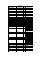
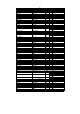
Library File names
Library file names are as follows:
"model name"_"drive mode"_"subwoofer use"or"floor-monitor use".cel.
"_pa": Passive mode
"_bi": Bi-amped mode
"_tri": Tri-amped mode
"_sub": Full-range speaker settings, when used in combination with subwoofer
"+subwoofer model": Combination of specific full range and subwoofer
"_moni": Settings for use as floor monitor.
Example: IF211595_bi_sub.cel
This file is a library which drives the IF2115/95 in bi-amp mode, and a sub-woofer.
(you should also recall a library for your subwoofer respectively).
Limiter settings
Default threshold levels were calculated from Noise (Continuous) power [W] and nominal impedance [Ω] (with the exceptions of a few models),
and set on the assumption of a maximum processor output level of +24dBu (SP2060 and DME24N) and an amp voltage gain of 26dB
(Tn or XP series amp set to 26dB gain with ATT 0dB; or 32 dB gain PC-1N or P series amp with ATT -6dB).
If you are using a setup that does not match these settings, change the threshold levels accordingly.
Example 1: If you are using the +18dBu MY8-DA96 card in the DME64/24N, raise the threshold by 6dB.
Example 2: If you are using an amp with 32dB gain and with ATT set to 0dB, drop the threshold by 6dB.
Attack time and release time were set as below.
Attack auto Mid = HPF wave length * 1/2
Release auto Mid = Attack time *16
Note: The use of a limiter does not guarantee the protection of your speakers!
The use of recommended limiters should be considered only the first step toward protecting your system.
Subwoofer Polarity, Positioning and Level
Normal polarity is appropriate where the subwoofer and full-range speakers are equidistant from the listening point.
In this case, the phase match will boost the bass level in the crossover range.
If the subwoofer and full-range speakers are not equally distant from the listening point,
however, then you may find that you get stronger bass-range energy and better results by reversing the polarity.
Try using both normal and reverse polarities, and then select the one which provides the best sound measurements
or subjective results at the listening point.
Note that the level required from the subwoofer will vary according to the application, the equipment mix, and the number of units.
Set the level to get the best result for your particular application and setup.
Also Note...
Set the power amp's HPF and LPF switches off. Also set YS Processing off (if using the Yamaha P series).
This library data was created using the SP2060 (Fs=96KHz).