PM1D System Software V1.
Contents New functionality in system software V1.4 . . . . . . . . . . . . . . . . . . . . . . . . . . . . . . . . . . . . 3 Digital gain for input channels / insert inputs . . . . . . . . . . . . . . . . . . . . . . . . . . . . . . . . . . 3 Procedure . . . . . . . . . . . . . . . . . . . . . . . . . . . . . . . . . . . . . . . . . . . . . . . . . . . . . . . . . . 5 Digital gain added to 2TR IN . . . . . . . . . . . . . . . . . . . . . . . . . . . . . . . . . . . . . . . . . . . . . . .
New functionality in system software V1.4 Thank you for purchasing the CS1D. This booklet explains the functionality that was added or changed in version 1.4 of the PM1D software. New functionality in system software V1.4 The following functionality and specifications have been added in version 1.4 of the PM1D system software.
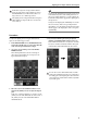
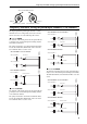
PM1D Manager for Windows Operating manual ■ If a digital I/O card (MY card) is assigned ■ If a GEQ output is assigned Digital gain Digital gain Digital gain can be used to adjust the input sensitivity in a range of +10 dB– –20 dB (the knob will not turn any further to the right beyond –20 dB).
Digital gain for input channels/insert inputs If 2TR IN is assigned to an input channel/insert input, the gain settings of the 2TR IN screen and the HA/INSERT screen will be linked. These settings cannot be set to different positions. The digital gain of an input channel/insert input to which 2TR IN is assigned will not be saved in the scene memory. Hint Settings for the digital gain of an input card are saved in the unit library.
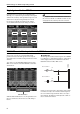
PM1D Manager for Windows Operating manual Digital gain added to 2TR IN Digital gain has been added to the six 2TR IN inputs, allowing you to adjust the input sensitivity in the digital domain. The sensitivity of the signal that is input to each 2TR IN can be adjusted independently for L and R. In conjunction with this, the display in the 2TR IN screen (MON/CUE function) has changed as follows. Hint Digital gain is valid even if ANALOG is selected as the source for 2TR IN 1 or 2TR IN 2.
BALANCE control for input channels/ST IN channels ■ VARI type MIX bus If a VARI type MIX bus is paired, the PAN parameter of the MIX bus will change to a BALANCE parameter. (A BAL knob will be displayed instead of a PAN knob in the PAN/ROUTING function CH to MIX screen.) In addition, if the VARI PAN LINK button is on for either of these two channels, the MIX bus BAL knob will be linked with the STEREO bus BAL knob.
PM1D Manager for Windows Operating manual Hint Even if the BALANCE button is on, the signal that is sent from those input channels to a FIX type MIX bus will not be affected if the FIXED MIX PAN button is turned off for both channels. In addition, the operation will change as follows if the PAN MODE “BALANCE” button is on.
Temporary monaural setting for paired input channels/ST IN channels Value of the BALANCE parameter PAN PAN R Always lit Odd-numbered (L) channel Always lit Even-numbered (R) channel L ■ Set to L-MONO The channels will remain paired, but the signal will temporarily become a monaural signal containing only the odd-numbered channel.
PM1D Manager for Windows Operating manual Even if L-MONO or R-MONO is selected, you can edit the parameters of the channel that was forced off. (However, the [ON] switch will be fixed at Off until you defeat the L-MONO or R-MONO setting, and cannot be changed.) A new preference setting [L,R-MONO SELECT ON PANEL] has been added to the UTILITY function PREFERENCE screen, allowing you to switch to the LR-MONO setting from the front panel.
Temporary monaural setting for paired input channels/ST IN channels The temporary monaural mode will be defeated, and the PAN (BALANCE) will return to the positions specified for the pair. The MIX send PAN setting (or BALANCE setting) will be set to the same position as TO ST. Hint In order to prevent accidents, it is possible to prohibit the operator from using the [SEL] switches to set/cancel pairing. To prohibit this, go to the PREFERENCE screen and turn the PROHIBIT PAIR CHANGE ON PANEL button on.
PM1D Manager for Windows Operating manual However, CUE on/off and Recall Safe that are not set independently for L and R in a ST IN channel will be linked or non-linked as a pair, even if LR-MONO is selected. For a ST IN channel, these parameters will always be linked regardless of the temporary monaural setting. • If the STEREO bus send PAN mode is set to BALANCE for an input channel, the MIX bus is paired, and the MIX bus type is VARI, the MIX bus PAN mode will also be BALANCE.
Temporary monaural setting for paired input channels/ST IN channels If PAN is changed: MONO mode PAIR PAIR mode L-MONO R-MONO PAN*1 → BALANCE BALANCE → PAN .*1 • BALANCE will be CENTER.*2 • The PAN that is sent to a MIX bus that is both paired and VARI-type will change to BALANCE, and set to CENTER. • The L channel PAN will be set to far left, and the R channel PAN will be set to far right.
PM1D Manager for Windows Operating manual Paired → LR-MONO PAN *1 BALANCE • The PAN value of the L/R channels and the PAN MODE setting will be temporarily preserved. • The L/R channel PAN will be CENTER.*2 • PAN to a paired VARI-type MIX bus will also be set to CENTER. • The BALANCE value of the L/R channels and the PAN MODE setting will be temporarily preserved. • The L/R channel PAN will be CENTER.*2 • BALANCE to a paired VARI-type MIX bus will change to PAN, and set to CENTER.
M/S decoding LR-MONO → L-MONO LR-MONO → R-MONO PAN *1 • The PAN value of the L/R channels and the PAN MODE setting will not change. • PAN to a paired VARI-type MIX bus will also remain unchanged. • The R channel ON/OFF will be turned OFF, and the L channel ON/OFF setting will not change. • The PAN value of the L/R channels and the PAN MODE setting will not change. • PAN to a paired VARI-type MIX bus will also remain unchanged.
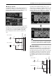
PM1D Manager for Windows Operating manual 3. Access the PAN/ROUTING function M/S screen. • The input unit meter displayed in the INPUT UNIT screen (SYS/W.CLOCK function) UNIT PATCH PEAK METER (PRE ATT.) DEEMPHASIS M/S DECODE ATT. A headroom margin of approximately 18 dB is maintained before M/S decoding. If the signal clips while you are using M/S decoding, you can use the attenuator to lower the level and input an unclipped signal if the clipping is below the headroom margin. 4.
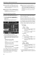
Tracking Recall function Tracking Recall function A “Tracking Recall” function has been added, which lets you add a pre-specified offset value to the value of each fader when a scene is recalled. You can use this Tracking Recall function when (for example) you want to make fine adjustments to the faders of specific channels, so that the specified offset value will automatically be added each time a scene is recalled. 3 1 2 1 TRACKING RECALL button This button switches Tracking Recall on/off.
PM1D Manager for Windows Operating manual Procedure Here's how to use the Tracking Recall function. 1. Access the SCENE function TRACKING RECALL screen. In the TRACKING RECALL screen, tracking can be turned on/off for each channel, and you can specify the offset value that will be applied to each channel for which Tracking Recall is on. 2. Press a MODE button (INPUT 1-48, INPUT 49-96, MIX, MATRIX) so that the desired channels appear in the screen. 3.
Tracking Recall function • If the OFFSET LOCK button is off for a channel that is channel-copied, the offset value will also be copied. When the power of the CS1D is turned off, and then on once again, the ENABLE button of the TRACKING RECALL area will be turned off for the sake of safety, disabling the Tracking Recall function.
YAMAHA CORPORATION IP 20 Printed in Japan Pro Audio & Digital Musical Instrument Division P.O.