UCA VS-10 VS-10 Home Theater Sound System Systèm audio home cinéma POWER STANDBY D I G I T A L OPEN NATURAL SOUND HOME THEATER SYSTEM VS-10 DOLBY D I G I T A L SURROUND OWNER’S MANUAL MODE D’EMPLOI MANUAL DE INSTRUCCIONES
IMPORTANT SAFETY INSTRUCTIONS 1 Read these instructions. CAUTION 2 Keep these instructions. RISK OF ELECTRIC SHOCK DO NOT OPEN 3 Heed all warnings. 4 Follow all instructions. 5 Do not use this apparatus near water. 6 Clean only with dry cloth. 7 Do not block any ventilation openings. Install in accordance with the manufacturer’s instructions. 8 Do not install near any heat sources such as radiators, heat registers, stoves, or other apparatus (including amplifiers) that produce heat.
IMPORTANT SAFETY INSTRUCTIONS FCC INFORMATION (for US customers only) Relocate either this product or the device that is being affected by the interference. Utilize power outlets that are on different branch (circuit breaker or fuse) circuits or install AC line filter/ s. In the case of radio or TV interference, relocate/ reorient the antenna. If the antenna lead-in is 300 ohm ribbon lead, change the lead-in to coaxial type cable.
CAUTION: READ THIS BEFORE OPERATING YOUR UNIT. 1 To assure the finest performance, please read this manual carefully. Keep it in a safe place for future reference. 2 Install this unit in a well ventilated, cool, dry, and clean place with at least 10 cm above, behind and on the both sides of this unit - away from direct sunlight, heat sources, vibration, dust, moisture, and/or cold.
PREPARATION FEATURES CONTENTS ● Home Theater Sound ● Includes Dolby Digital, Dolby Pro Logic and DTS Decoders PREPARATION FEATURES .................................................................. 1 GETTING STARTED ................................................. 2 NAMES OF ALL PARTS ............................................ 4 SPEAKER PLACEMENT .......................................... 6 INSTALLATION ......................................................... 7 CONNECTIONS .........................
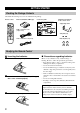
GETTING STARTED Checking the Package Contents Check that the following accessories are included in the package.
GETTING STARTED Operational Area of the Remote Control ■ Battery replacement cycle Control center Replace all four batteries when the operational range of the remote control starts to become shorter. POWER ■ Precautions on handling the remote control D I G I T A L DOLBY D I G I T A L NATURAL SOUND HOME THEATER SYSTEM VS-10 SURROUND Approx. 20 cm – 6 m 30° 30° • The remote control may not be able to operate the control center when an object blocks the remote control sensor on the unit.
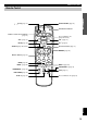
NAMES OF ALL PARTS Control Center (Front Panel) POWER (page 17) Turns the power of the control center on and off. This button also turns off the subwoofer’s power when the YAMAHA NXSW10 (sold separately) is connected. The STANDBY indicator lights when power is turned off using p on the remote control. STANDBY indicator When this indicator lights up, this unit consumes a very small quantity of power to receive infrared-signals from the remote control.
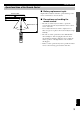
NAMES OF ALL PARTS Remote Control PREPARATION p (power) (page 17) EFFECT ON/OFF (page 23) Transmission indicator ON/OFF EFFECT Remote control selector buttons (page 27) VS10 TV VCR CBL Not used with this unit.
SPEAKER PLACEMENT Although speakers should ideally be placed as shown below, satisfactory effects may be obtained even if you do not strictly follow these guidelines. Main speakers Place in each side of the TV monitor. Center speaker (sold separately) Place above the TV monitor in the center. Right rear speaker 1.5 - 1.8 m Left rear speaker Rear speakers (sold separately) Place behind or to the sides of the listening position. Subwoofer (sold separately) Place near the right or left main speaker.
INSTALLATION Depending on room conditions, the control center can be installed vertically or horizontally. Installing the Control Center Horizontally PREPARATION Precautions before installation • Do not touch the adhesive surface after peeling off the pad as this will weaken its adhesive strength. • Thoroughly wipe clean the surface where the pad is to be applied. Note that adhesive strength is weakened if the surface is dusty, oily or wet.
INSTALLATION Installing the Control Center Vertically Apply the two supplied side pads to the side of the control center and attach to the supplied supporting stand. 1 Peel off the seals of the side pads and apply to the two indented parts (near to the front panel) on the left side of the control center. Peel off the seal. Front panel Side pad Apply to the indented part. 2 Attach the control center with the pads applied side facing down to the supporting stand as shown in the illustration below.
CONNECTIONS CAUTION Always be sure to turn off the power of the control center and any component to be connected when making connections. PREPARATION To ensure proper connections • Connect the white plug of the connection cord to the left “L” (white) audio signal terminal and connect the red plug to the right “R” (red) terminal. • Insert the plug securely. If the plug is not inserted securely, noise may result or sound may not be output.
CONNECTIONS Connecting a TV or VCR ■ Connecting a TV (monitor) Control center (rear panel) VIDEO SIGNAL MONITOR OUT VIDEO OUT + – – DO NOT CONNECT THIS UNIT TO SPEAKERS OTHER THAN NX-VS10M + MARK Video connection cord (supplied) MAIN SPEAKERS DIGITAL 1 VIDEO 1 (V/PCM) TV OUT SUBWOOFER SYSTEM CONNECTOR INPUT AUDIO IN L L As this terminal is used for an examination in the factory, do not connect any equipment to this terminal.
CONNECTIONS ■ Connecting a DVD player, cable TV tuner, etc. Control center (rear panel) Anti-dust cap MONITOR OUT VIDEO IN + – PREPARATION Anti-dust cap VIDEO SIGNAL VIDEO IN – DO NOT CONNECT THIS UNIT TO SPEAKERS OTHER THAN NX-VS10M Remove the cap covering the DIGITAL 1 terminal (optical) when connecting an optical fiber cable. Safely store the cap and always re-insert it in the terminal when the terminal is not in use. (This cap prevents the entrance of dust.
CONNECTIONS ■ Connecting a camcorder, video game player, etc. Control center (Front panel) Anti-dust cap Remove the cap covering the DIGITAL 2 terminal (optical) when connecting an optical fiber cable. Safely store the cap and always re-insert it in the terminal when the terminal is not in use. (This cap prevents the entrance of dust.
CONNECTIONS Connecting the Main Speakers Connect the main speakers to the control center. Note Right main speaker (Rear panel) Left main speaker (Rear panel) 1 2 Bare wire 2 3 PREPARATION • Do not connect any speakers to the speaker terminals on the control center except for the supplied main speakers (NX-VS10M). Damage may result if a different speaker is connected. Open the tab. Insert the bare wire of the speaker cord into the hole.
CONNECTIONS Connecting the Control Center to the Subwoofer Although the VS-10 alone can be used to reproduce rich and natural sounding audio, the additional use of a subwoofer allows you to enjoy powerful bass tones. Connecting the YAMAHA subwoofer, center speaker and rear speakers NX-SW10 (sold separately) can not only increase bass sensitivity but improve the surround effect.
ADJUSTING THE SPEAKER OUTPUT LEVELS Speaker output levels may be adjusted using the remote control before playback by following the steps. 2 ON/OFF 1 EFFECT VS10 TV VCR Press TEST. A test tone (like pink noise) will be output in the following order. PREPARATION When reproducing the source encoded with a Dolby Digital, Dolby Surround or DTS, it is important to adjust the sound output level heard at the listening position to the same from each speaker.
ADJUSTING THE SPEAKER OUTPUT LEVELS y • When only the VS-10 is connected: Adjust the sound output levels of the rear virtual speakers and the main speakers so that they become almost the same. • When the NX-SW10 is connected: Adjust the sound output levels of the center speaker and the rear speakers so that they become almost the same as that of the main speakers.
OPERATION OPERATING THE UNIT Enjoying the Home Theater Sound System This section describes how to select the input source to enjoy the sound from a TV, VCR, DVD player, satellite tuner or video game player with the VS-10 and to adjust the volume. First turn on the power of the playback component and the TV, and then follow the steps described below.
OPERATING THE UNIT Switching the input mode CAUTION This function allows you to switch the input mode of the component connected to the DIGITAL 1 or DIGITAL 2 terminal to “Auto Mode” or “dts Fix”. Auto Mode : This recognizes the PCM signal such as a CD, Dolby digital signal or DTS signal automatically. dts Fix : This fixes to a DTS signal. Normally, the playback can be performed with the “Auto Mode”.
USING CONVENIENT FUNCTIONS You can use convenient functions with the remote control during a playback. ı Listening to sound clearly at low levels Press NIGHT MODE. ON/OFF EFFECT VS10 TV VCR CBL CH – VOL VOL + CH D E (When the subwoofer is connected.) B A MUTE DSP AV MEMORY 1 2 3 4 5 6 7 8 9 MENU – LAST + 0 SUBWOOFER – ENTER To cancel NIGHT MODE, press NIGHT MODE again. Notes • The NIGHT MODE does not function when the headphones are connected.
USING CONVENIENT FUNCTIONS ‰ Calling Up Your Favorite Settings Each MEMORY 1, 2 or 3 button can memorize the current input and the settings of DSP mode, SUBWOOFER level, TRUBASS and NIGHT MODE. Once the settings are preset, you can call up each MEMORY 1, 2 or 3 button anytime by simply pressing one of the MEMORY buttons. Memorizing the settings to each MEMORY 1, 2 or 3 button Press and hold the MEMORY 1, 2 or 3 button to be memorized for about 3 seconds.
DSP PROGRAM (DIGITAL SOUND FIELD PROCESSOR EFFECT) You can recreate the sound and feel of a movie theater, concert hall or other location by selecting from any of eight DSP programs best suited to the source being reproduced. This allows you to enjoy the full experience of digital systems such as DOLBY DIGITAL, DOLBY PRO LOGIC, DTS, or YAMAHA CINEMA DSP (Digital Sound field Processor).
DSP PROGRAM (DIGITAL SOUND FIELD PROCESSOR EFFECT) No. 7 Program name Features and applicable sources This program is designed specially to enhance monaural source such as an old monaural movie. Sound field effects and moderate resonance processing are used to bring fuller life to the monaural audio. MONO MOVIE Note • When “GAME” or “HALL” is selected for a 2 -channel source, no sound is heard from the center speaker even if the YAMAHA NX-SW10 is connected. ■ When the headphones are connected: No.
DSP PROGRAM (DIGITAL SOUND FIELD PROCESSOR EFFECT) Notes • Be sure to select the DSP program best suited for the atmosphere of the source being listened to. • The last selected DSP program for each input source (VIDEO 1, TV, VIDEO 2, DIGITAL 1 and DIGITAL 2) is stored in memory. So, when the input source is changed, the DSP program is automatically changed to the last selected one correspondingly. ■ To cancel sound field effects (using the remote control) Press EFFECT ON/OFF.
MENU FUNCTIONS The menu functions include: “Auto Power” for setting automatic power on/off, “Dimmer” for adjusting display brightness, “Input Name” for naming inputs, “Center Delay” for adjusting the delay time used for the sound from the center speaker and “Delay Time” for adjusting the delay time used for the surround sound. Adjustments on the menu functions should be performed with the remote control.
MENU FUNCTIONS Adjusting Display Brightness 3 Press MENU + or – to select the name. The display brightness of the control center can be adjusted as follows. 1 Press MENU to display “Dimmer”. The current brightness level (such as “Dimmer: ±0”) is displayed. – + LAST ENTER If you select VIDEO 2 in step 2 above, names are displayed in the following order when you press +. MENU VIDEO 2 0 VIDEO 2: CABLE VIDEO 2: GAME 2 VIDEO 2: MD Press MENU + or – to adjust the brightness.
MENU FUNCTIONS Adjusting the Center Delay Time The center delay time is the time difference between the beginning of the sound from the main speakers and the beginning of the sound from the center speaker. When the other DSP program except for SILENT CINEMA is selected, it is possible to adjust the center delay time. This adjusts the delay between the main sound (on the main speakers) and dialog, etc. (on the center speaker).
REMOTE CONTROL OPERATING OTHER COMPONENTS USING THE REMOTE CONTROL Setting the manufacturer code for your TV, VCR or cable TV tuner/satellite tuner on the remote control allows you to operate not only the VS-10 but also your TV, VCR or cable TV tuner/satellite tuner using the remote control. Notes • Remote control of some component may not be possible depending on the model and the year of make even though its manufacturer is listed on page i (at the end of this manual).
OPERATING OTHER COMPONENTS USING THE REMOTE CONTROL ■ Precautions when performing preset The transmission indicator goes out once the manufacturer code is set properly. If the transmission indicator does not go out, or if it flashes and then goes out, repeat the procedure from step 1. Pay attention to the following points when you repeat the preset procedure. • Check the manufacturer code number. • Check that the correct remote control selector button has been selected when setting the manufacturer code.
OPERATING OTHER COMPONENTS USING THE REMOTE CONTROL Controlling a TV You can control your TV by setting the corresponding manufacturer code for the remote control selector button “TV”. Press TV.
OPERATING OTHER COMPONENTS USING THE REMOTE CONTROL Controlling a VCR You can control your VCR by setting the corresponding manufacturer code for the remote control selector button “VCR”. Press VCR.
APPENDIX GLOSSARY ■ Encode/Decode When a signal or other information is processed, compressed and digitized, this is called encoding. Encoding can be used to record an extremely large amount of information on a single CD or DVD. An encoded signal cannot be listened to directly. It must be returned to its original state (i.e. audible sound) and this is called decoding.
TROUBLESHOOTING Be sure to investigate thoroughly before requesting repairs or after service. If it cannot be corrected, or if the problem is not listed in the SYMPTOM column, disconnect the power cord and contact your authorized YAMAHA dealer or service center. Notes • Sometimes the unit may cease to recognize operations due to a mistaken operation or as a result of strong external noise (such as irregular voltage due to shock of impact, excessive static electricity, or lightning strike).
SPECIFICATIONS Control Center General ■ Amplifier Section Minimum RMS Output Power Main .......................... 25 W + 25 W (1 kHz, 10% THD, 6 ohms) Power Supply [Europe and U.K. models] ................................ AC 230 V, 50 Hz [U.S.A. and Canada models] ............................ AC 120 V, 60 Hz [Australia model] .............................................. AC 240 V, 50 Hz Signal-to-Noise Ratio ............................... 90 dB (VIDEO 1, IHF-A) Total Harmonic Distortion .............
INDEX A M Adjusting display brightness ............................................. 25 Adjusting the bass (subwoofer level) ................................ 19 Adjusting the center delay time ......................................... 26 Adjusting the delay time .................................................... 26 Adjusting the volume level ................................................ 17 Auto Power on/off ............................................................. 24 Manufacturer codes .........
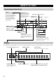
LIST OF MANUFACTURER’S CODES LISTES DES CODES FABRICANT LISTA DE CÓDIGOS DE FABRICANTES TV A-MARK 1161 A TANDY 0941 ABEX 1151 ADMIRA 1141 ADVENTURA 1131 AIKO 1121 AIWA 1451 AKAI 0331, 1101, 1111 ALBA 0431 ALLERON 1091 AMBASSADOR 1081 AMSTRAD 0481, 1081 ANAM 0251, 1041, 1051, 1061, 1071 ANAM NATIONAL 1041 AOC 0361, 1021, 1031 1111, 1161 ARCHER 1161 AUDIOSONIC 1001 AUDIOVOX 1051, 1161 BAUER 0441 BAUR 1001 BEIJING 1511, 1551, 1561 BELCOR 1031 BELL & HOWELL 0981, 0991 BEON 1001 BRADFORD 1051 BROCKWOOD 1031 BROK
SEARS 0101, 0161, 0171, 0351, 0451, 0521, 0621, 0761, 0801, 0861, 0971, 0981, 1091 SHANGHAI 1561, 1681 SHARP 0461, 0471, 0541, 0661, 0911, 0941, 1141 SHOGUN 1031 SIGNATURE 0991, 1771 SIMPSON 0581, 0961 SOLAVOX 1151 SONOKO 1001 SONTEC 1001 SONY 0371, 0451, 0661, 0841, 0951, 1281, 1441 SOUNDESIGN 0861, 0961, 1051, 1091 SOUNDWAVE 1001 SPECTRICON 1161 SQUAREVIEW 0481 SSS 1031, 1051 STAR-LITE 1051 SUPREX 0951 SUPRE-MACY 1131 SURPA 0351, 0971 SYLVANIA 0101, 0361, 0441, 0581, 0591, 0601, 0611, 0631, 0961, 1111 SY
COMTRONICS 0214, 0274 EAGLE COMTRONICS 0274 EASTERN 0064 ELECTRICORD 0204 ELECTUS 0264 GE 0114, 0124 GEC CABLE SYSTEM 0194 HAMLIN H5 0674 HAMLIN H6 0664 HAMLIN H6S 0654 HAMLIN H8 0644 HAMLIN H9 0634 JERROLD 0254 JERROLD 400L 0624 JERROLD 450L 0614 JERROLD 550 0604 JERROLD OSD CATV 0594 JERROLD SPRUCER 0434 MAGNAVOX/PHILIPS 0414, 0424 MAMM 0294 MEMOREX 0384 MOVIE TIME 0144, 0204 NORTHCOAST 0014 NSC 0144 OAK 0104 OAK SIGMA 450 0544 OAK SIGMA 550 0534 PANASONIC TZ 120/130 0474 PANASONIC TZ 170/180 0444 PANASON
YAMAHA YAMAHA YAMAHA YAMAHA YAMAHA YAMAHA YAMAHA ELECTRONICS CORPORATION, USA 6660 ORANGETHORPE AVE., BUENA PARK, CALIF. 90620, U.S.A. CANADA MUSIC LTD. 135 MILNER AVE., SCARBOROUGH, ONTARIO M1S 3R1, CANADA ELECTRONIK EUROPA G.m.b.H. SIEMENSSTR. 22-34, 25462 RELLINGEN BEI HAMBURG, F.R. OF GERMANY ELECTRONIQUE FRANCE S.A. RUE AMBROISE CROIZAT BP70 CROISSY-BEAUBOURG 77312 MARNE-LA-VALLEE CEDEX02, FRANCE ELECTRONICS (UK) LTD. YAMAHA HOUSE, 200 RICKMANSWORTH ROAD WATFORD, HERTS WD1 7JS, ENGLAND SCANDINAVIA A.
Connecting to a TV (monitor), DVD player, Satellite tuner and VCR Connection Guide Control center VS-10 (rear panel) VIDEO SIGNAL MONITOR OUT V + – DO NOT CONNECT THIS UNIT TO SPEAKERS OTHER THAN NX-VS10M + MARK MAIN SPEAKERS DIGITAL 1 VIDEO 1 (V/PCM) OUT TV SUBWOOFER SYSTEM CONNECTOR INPUT V DVD player V R L VIDEO OUT R L V OPTICAL DIGITAL OUTPUT TV (monitor) V R L Satellite tuner VCR VIDEO OUT L AUDIO OUT R VIDEO OUT L AUDIO OUT R V Supplied cords V Audio connection cord (2
Connecting to a camcorder and video game player Connection Guide Connecting the main speakers (supplied) and YAMAHA subwoofer/ center speaker/rear speakers NX-SW10 (sold separately) Main speaker NX-VS10M Right Main speaker NX-VS10M Left REAR, CENTER SPEAKERS POWER STANDBY DIGITAL2 VIDEO2 PHONES + + – – SILENT + – – + DO NOT CONNECT THIS UNIT TO SPEAKERS OTHER THAN NX-VS10E, NX-VS10C DO NOT CONNECT THIS UNIT TO SPEAKERS OTHER THAN NX-VS10M MAIN SPEAKERS V V L R Subwoofer SW-VS10 VID