
User Manual


Speaker System Design Guide for
Yamaha Sound System Simulator
1. Setting the speaker arrangement
Y-S
3
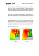
can produce contour diagrams for each speaker array or for each speaker within a
speaker array. This allows the user to adjust the speaker arrangement while checking the
floor-level coverage area. If the areas covered by individual speakers overlap significantly,
sections of phase interference appear over a wide area and cause reinforcements (peaks)
and cancellations (dips)*. Y-S
3
can produce color maps of the sound pressure distribution
that can be used to evaluate phase interference. However, because Y-S
3
only computes the
effects of direct sound, the computed results will be different than the actual sound pressure
distribution in a hall, which is affected by direct and reflected sound. When designing a
speaker system, it is important to understand how the effects of reflected sound will be
manifested.
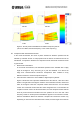
In the example below, a two-speaker array is placed in the center position. This example
compares the computed areas of phase interference for the given speaker configuration to
the actual measured sound pressure distribution in a real hall.
* Please note that all speakers produce phase interference when arrayed to some extent.
; Speaker target configuration
¾ How splay angle affects the speaker targets
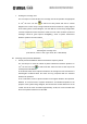
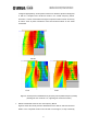
The first example shows an evaluation of each speaker target based on the splay
angle. In Y-S
3
, the user can click to switch to Single Mode display and view
contour diagrams of the target areas of each speaker in the array. The user can
also change the bandwidth and the central frequency of the contour diagram by
changing the Frequency and Band items in the upper left of the window. The
example below shows the average of the results for each octave (1/1 OCT Band).
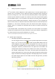
For example, if Splay Angle is set to 60.0, the black squares that represent the
speaker targets appear very close to the walls, giving the impression that the splay
angle is too wide for the seating arrangement. If the Splay Angle is then set to 50.0,
the speaker targets appear near the middle of the left and right areas, just about
where they should be.
Figure 1: Splay angle adjustment (left: 60.0, right: 50.0)
3