UTILITY CAR OWNER’S/ OPERATOR’S MANUAL G21A 10/31/00 1PC - G21A O/M LIT196261100 *LIT196261100* USA Yamaha Motor Corp., USA Cypress, California made in YAMAHA MOTOR MANUFACTURING CORP. OF AMERICA LIT-19626-11-00 Printed in U.S.A.
G21A O_M IFC 8/8/00 7:56 AM Page 1 WARNING The engine exhaust from this product contains chemicals known to the State of California to cause cancer, birth defects or other reproductive harm.
G21A O_M IFC 8/8/00 7:56 AM Page 1 WARNING The engine exhaust from this product contains chemicals known to the State of California to cause cancer, birth defects or other reproductive harm.
LIT_19626_11_00 3/22/01 1:06 PM Page i INTRODUCTION Congratulations on your purchase of a Yamaha utility car. This manual contains information you will need for proper operation, maintenance, and care of your utility car. A thorough understanding of these simple instructions will help you to obtain maximum enjoyment from your new Yamaha. If you have any questions about the operation or maintenance of your utility car, please consult a Yamaha dealer.
LIT_19626_11_00 3/22/01 1:06 PM Page ii IMPORTANT MANUAL INFORMATION Particularly important information is distinguished in this manual by the following notations: The Safety Alert Symbol means ATTENTION! BE ALERT! YOUR SAFETY IS INVOLVED! WARNING Failure to follow WARNING instructions could result in severe injury or death to the utility car occupants, a bystander, or a person inspecting or repairing the utility car.
LIT_19626_11_00 3/22/01 1:06 PM Page iii CONTENTS WARRANTY 1 IMPORTANT LABELS 2 OPERATOR SAFETY 3 MAINTENANCE SAFETY PROGRAM 4 CONTROLS 5 PRE-OPERATION CHECKS 6 OPERATION 7 MAINTENANCE 8 1 STORAGE 9 SPECIFICATIONS 10 WIRING 11 UTILITY iii
LIT_19626_11_00 3/22/01 1:06 PM Page iv WARRANTY YAMAHA MOTOR CORPORATION, U.S.A. G21A UTILITY VEHICLE LIMITED WARRANTY 1 2 Yamaha Motor Corporation, U.S.A. hereby warrants that any new G21A Utility Vehicle purchased from an authorized Yamaha dealer in the United States, will be free from defects in material and workmanship for the period of time stated herein, subject to the stated limitations.
LIT_19626_11_00 3/22/01 1:06 PM Page v WARRANTY YAMAHA MOTOR MANUFACTURING CORPORATION OF AMERICA SPECIALTY VEHICLE ENGINES EMISSION CONTROL WARRANTY 1 2 YOUR WARRANTY RIGHTS AND OBLIGATIONS In complance with the California Air Resources Board, Yamaha Motor Manufacturing Corporation of America is pleased to explain the emission control system warranty on your 1996 or later specialty vehicle engine.
LIT_19626_11_00 3/22/01 1:06 PM Page vi WARRANTY 3. Ignition System Spark plugs * Magneto or electronic ignition system Spark advance/retard system 4. Exhaust Gas Recirculation (EGR) System EGR valve body, and carburetor spacer if applicable EGR rate feedback and control system 5. Air Injection System Air pump or pulse valve Valves affecting distribution of flow Distribution manifold 6. Catalyst or Thermal Reactor System Catalytic converter Thermal reactor Exhaust manifold 7.
LIT_19626_11_00 3/22/01 1:07 PM Page 2-1 IMPORTANT LABELS SAFETY AND INSTRUCTION LABELS 4 1 6 5 1 2 WARNING 2 9 Please read the following labels carefully before operating your utility car, and promptly replace any labels which become damaged or removed.
LIT_19626_11_00 3/22/01 1:07 PM Page 2-2 IMPORTANT LABELS 9 1 2 3 4 7 8 Y-852 Y-101 8 7 5 9 6 7 8 9 Y-851 UTILITY CAR SERIAL NUMBER 0000 0 10 JR6-0 The utility car serial number is stamped in the location shown. 11 Y-102a 2-2 NOTE: The first three digits of the serial number are for model identification; the remaining digits are the unit production number. Keep a record of these numbers for reference when ordering parts from a Yamaha dealer.
LIT_19626_11_00 3/22/01 1:07 PM Page 3-1 ! OPERATOR SAFETY Yamaha utility cars are designed to be simple to operate. However, be sure to observe the following: BEFORE OPERATING THE UTILITY CAR 1 2 ● Read this Owner’s/Operator’s manual and all safety and instruction labels on the utility car before operating. ● Perform the pre-operation checks found in Section 6 of this manual. 4 ● Only authorized people should drive the utility car, from the driver’s side only, and only in designated areas.
LIT_19626_11_00 3/22/01 1:07 PM Page 3-2 ! OPERATOR SAFETY 1 2 3 ● Keep your hands on the steering wheel and your eyes on the path ahead. ● Use extra care in congested areas or when backing up. Always back up slowly, and watch carefully. ● Avoid starting or stopping abruptly. ● Vary the speed of the utility car to match the terrain of your surroundings. ● Avoid turning the steering wheel too sharply at higher speeds.
LIT_19626_11_00 3/22/01 1:07 PM Page 3-3 ! OPERATOR SAFETY LOADING/TOWING ● ● ● ● ● Y-105 ● Y-106 ● ● ● Do not drive across the face of slope. Avoid poor driving conditions such as wet lawns and rough surfaces. Vehicle handling and stability may be reduced. Stop the engine, remove ignition key and make sure trailer is correctly installed before towing trailer. Do not allow people to ride in cargo bed or trailer.
LIT_19626_11_00 3/22/01 1:07 PM Page 3-4 MAINTENANCE SAFETY PROGRAM 1 2 3 MAINTENANCE REQUIRED FOR UTILITY CAR SAFETY 6 7 ● Preventative Maintenance. Perform all scheduled maintenance in accordance with manufacturer’s recommendations to provide the user with a safe, properly operating utility car. ● Personnel. Allow only qualified, trained, and authorized personnel to inspect, adjust, and maintain utility cars. ● Parts and Materials.
LIT_19626_11_00 3/22/01 1:07 PM Page 3-5 MAINTENANCE SAFETY PROGRAM FUEL HANDLING/ STORAGE AND BATTERY CHARGING 1 2 Take the following precautions to ensure maintenance worker safety: ● Supervise the storage and handling of liquid fuels in accordance with applicable fire and safety requirements. ● Only use battery changing and charging facilities and procedures that are in accordance with applicable ordinances and regulations.
LIT_19626_11_00 3/22/01 1:07 PM Page 3-6 CONTROLS FEATURES 1 1 9 8 1 Steering wheel 2 Seat 3 Battery 4 Brake pedal 5 Parking brake pedal 6 Accelerator pedal 7 Drive selector lever 8 Main switch 9 Oil warning light a Choke knob b Front cowl c Front tire d Front bumper e Rear cowl f Rear tire g Fuel cap 6 5 2 4 3 Y-12 4 5 6 7 2 3 8 14 9 15 10 13 7 11 10 16 Y-107 11 12 5-1 UTILITY
LIT_19626_11_00 3/22/01 1:07 PM Page 3-7 CONTROLS MAIN SWITCH 1 The main switch controls the following items: OFF Ignition circuit is switched off. The key can be removed only in this position. OF F 2 3 ON 4 Y-15 5 ON Electrical circuits are switched on. The utility car can be driven. OF F 6 ON 7 Y-16 8 OIL WARNING LIGHT W AO I L RN ING ON A When the engine oil level falls below an acceptable level, this light comes on.
LIT_19626_11_00 3/22/01 1:07 PM Page 3-8 CONTROLS DRIVE SELECT LEVER 1 The drive select lever is used to shift the utility car into forward or reverse. After coming to a complete stop, move the lever to the desired position. 2 3 Y-18 4 Lever Position Car Movement F R FORWARD REVERSE NOTE: The back-up buzzer will sound when the drive select lever is turned to “R.” 5 6 Y-109 7 ACCELERATOR PEDAL A 8 The accelerator pedal controls the utility car’s speed.
LIT_19626_11_00 3/22/01 1:07 PM Page 3-9 CONTROLS PARKING BRAKE PEDAL 1 Press down on the parking brake pedal whenever parking the utility car. A Y-22 å Parking brake pedal 2 NOTE: Release the parking brake by depressing the accelerator pedal. 3 CHOKE KNOB 4 Pull and hold out choke knob when starting a cold engine. Release the knob after the engine starts. 5 å Choke knob A E OK CH 6 Y-23 TOW HITCH 7 Use the tow point within the specified weight limits.
LIT_19626_11_00 3/22/01 1:07 PM Page 3-10 PRE-OPERATION CHECKS 1 Pre-operation checks should be made each time you use your utility car. Get in the habit of performing the following checks in the same way so that they become second nature. 2 WARNING 3 ● 4 5 ● 6 Be sure the main switch key is removed before performing the pre-operation checks to prevent accidental starting, and apply the parking brake to keep the car from moving.
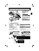
LIT_19626_11_00 3/22/01 1:07 PM Page 3-11 PRE-OPERATION CHECKS CARGO BED 1 Lift the cargo bed for engine servicing. 1. Pull the bed latch towards the rear with right hand. 2. Lift the cargo bed with left hand. 3. Lift the cargo bed up until the prop rod latches in place. 2 3 Y-112 4 WARNING ● Y-113 ● ● Remove the main switch key and apply the parking brake before lifting the cargo bed. Otherwise the vehicle could unexpectedly move. Never drive the car with the bed in the up position.
LIT_19626_11_00 3/22/01 1:07 PM Page 3-12 PRE-OPERATION CHECKS 1 FUEL SYSTEM A C E F B Make sure there is sufficient fuel in the tank, and check fuel line and connections for leakage. 2 3 Y-850 WARNING 4 Gasoline and its vapors are highly flammable and explosive. ● Do not smoke when refueling and keep away from sparks, flames, or other sources of ignition. ● Stop engine and allow it to cool for several minutes before refueling. ● Refuel in a well-ventilated area.
LIT_19626_11_00 3/22/01 1:07 PM Page 3-13 PRE-OPERATION CHECKS ENGINE OIL 1 With the utility car parked on level ground, remove the dipstick and make sure the engine oil is between the MIN and MAX marks (the crosshatched area on the end of the dipstick). 3 Y-514 å Oil level dipstick ∫ Maximum oil level ç Safe operating range B MIN C 4 If the oil level is below the MIN mark on the dipstick, add oil through the oil filler hole until the oil level is between the MIN and MAX marks.
LIT_19626_11_00 3/22/01 1:07 PM Page 3-14 PRE-OPERATION CHECKS BATTERY 1 Check that the battery is held securely in place to prevent the battery from being damaged from vibration or jarring. Also check that no battery caps are missing to prevent battery acid from spilling from the battery. Check the battery terminals for corrosion. 2 3 4 TIRE CONDITION Tire Air Pressure 5 Check the tire air pressure before operating the utility car.
LIT_19626_11_00 3/22/01 1:07 PM Page 3-15 PRE-OPERATION CHECKS 1 STEERING SYSTEM Check the steering system for excessive freeplay by: ● moving the steering wheel up and down, and back and forth. ● turning the steering wheel slightly to the right and left. Y-116 If you feel excessive freeplay, or hear rattling sounds which may indicate loose steering components, consult a Yamaha dealer. 2 3 4 5 BACK-UP BUZZER Check the back up buzzer by moving the drive select lever to “R” for reverse.
LIT_19626_11_00 3/22/01 1:07 PM Page 3-16 PRE-OPERATION CHECKS 1 Parking Brake Pedal A Make sure the parking brake pedal locks in place with a positive click, and releases when the accelerator pedal is pressed. 2 å Parking brake pedal 3 Y-22 NOTE: Release the parking brake by depressing the accelerator pedal. 4 Accelerator Pedal 5 WARNING Before checking operation of the accelerator pedal, be sure the main switch is in the “OFF” position.
LIT_19626_11_00 3/22/01 1:07 PM Page 7-1 OPERATION 1 STARTING 1. With the parking brake applied, turn the drive select lever to “F” for forward, or “R” for reverse. CAUTION Y-18 Do not shift from “F” forward to “R” reverse while the utility car is moving. 3 4 2. Turn the main switch to “ON.” OF F 2 WARNING ON Do not depress the accelerator pedal when turning on the main switch or the utility car may suddenly start moving. 5 6 Y-16 3. Pull the choke knob out and hold it while starting.
LIT_19626_11_00 3/22/01 1:07 PM Page 7-2 OPERATION STOPPING 1 B To stop the utility car, gradually press down on the brake pedal. å Brake pedal 2 When the car has come to a stop, apply the parking brake pedal and turn the main switch to “OFF.” A 3 Y-65 ∫ Parking brake pedal 4 CAUTION Do not hold the utility car on an incline with the accelerator – use the brake. 5 6 Y-117 LOADING/TRAILER TOWING WARNING 7 Be sure to check “SAFETY INFORMATION” carefully before loading or towing.
LIT_19626_11_00 3/22/01 1:07 PM Page 8-1 MAINTENANCE PERIODIC MAINTENANCE CHARTS Regular maintenance is required for the best performance and safe operation of your utility car. WARNING Be sure to turn off the main switch and apply the parking brake when you perform maintenance unless otherwise specified. If the owner is not familiar with machine servicing, this work should be done by a Yamaha dealer or other qualified mechanic.
LIT_19626_11_00 3/22/01 1:07 PM Page 8-2 MAINTENANCE 1 C - CHECK CA - CHECK AND ADJUST R - REPLACE 1000 rds 1000 hrs 5000mls 8000 kms (Every 4 years) Page R R R 8-5 CA CA CA * Check starter V-belt for damage and tension C C C * Check drive belt for slippage, wear or scratches C C C 8-8 Check sliding sheave and ramp shoes; Grease secondary sheave bearing.
LIT_19626_11_00 3/22/01 1:07 PM Page 8-3 MAINTENANCE EXHAUST EMISSION CONTROL SYSTEM AND COMPONENTS • • • • • Item CARB. ASSY., LH., JT., CARBURETOR 2 & JT., CARBURETOR 1 T.C.I. MAGNETO ASSY. & PLUG, SPARK CRANKCASE 1 & HEAD, CYLINDER 1 AIR FILTER ASSY. MUFF., 2 1 Acronym CARB (Carburetor) 2 El (Electronic Ignition) 3 PCV (Positive Crankcase Ventilation) ACL (Air Cleaner) 4 5 The above items and the corresponding acronyms are provided in accordance with U.S.
LIT_19626_11_00 3/22/01 1:07 PM Page 8-4 MAINTENANCE Spark Plug Inspection 1 2 You should periodically remove and inspect the spark plug. Dirty or worn spark plugs can cause poor performance. B å Spark plug ∫ Spark plug cap 3 A Y-516 4 1. Check for discoloration and heavy carbon deposits. The normal electrode color will be tan. If it is not, replace it. 2. Check the spark plug type, and check the spark plug gap with a feeler gauge.
LIT_19626_11_00 3/22/01 1:07 PM Page 8-5 MAINTENANCE Engine Oil Replacement 1. Warm up the engine for several minutes, place the utility car on a level surface, then stop the engine. WARNING 1 2 3 Use caution not to touch hot engine oil or hot engine parts, during the following procedure. 4 2. Place an oil pan under the engine drain plug. 3. Remove the oil drain plug and let the oil drain completely.
LIT_19626_11_00 3/22/01 1:07 PM Page 8-6 MAINTENANCE 1 å Oil filler hole A CAUTION 2 3 Y-515 4 Air Filter To remove the air filter elements: A 5 B A 1. Unlatch the air filter cover clips and remove cover. A å Air filter cover clips ∫ Air filter cover 6 7 Y-518 2. Lift the air filter and pre-filter out of the air filter case. 8 9 Use care not to fill past the MAX dipstick mark, and be sure no foreign material enters the crankcase.
LIT_19626_11_00 3/22/01 1:07 PM Page 8-7 MAINTENANCE A Inspection and cleaning: B 1 3. Wash the foam pre-filter in soap and water. Allow it to dry. Y-508 å Soap and water ∫ Foam element 2 4. Check the filter element. If damaged or dirty, replace it. 3 CAUTION 4 Do not wring out the foam pre-filter, this could cause it to tear. 5. To replace the elements, reverse the above steps. 5 6 CAUTION The pre-filter has a notch on one side. It will only fit in the case one way.
LIT_19626_11_00 3/22/01 1:07 PM Page 8-8 MAINTENANCE Drive Belt 1 To remove the drive belt: 2 1. Set the drive select lever halfway between forward and reverse. 3 2. Pull up on the drive belt and push it outward over the edge of the secondary sheave. 4 3. Turn the secondary sheave clockwise and the drive belt will roll off the sheave. 5 Y-60 4. Remove the drive belt from the primary sheave.
LIT_19626_11_00 3/22/01 1:07 PM Page 8-9 MAINTENANCE Battery 1 WARNING Battery electrolyte is poisonous and dangerous, causing severe burns, etc. It contains sulfuric acid. Avoid contact with skin, eyes, or clothing. Antidote: EXTERNAL: Flush with water. INTERNAL: Drink large quantities of water or milk. Follow with milk of magnesia, beaten egg, or vegetable oil. Call physician immediately. EYES: Flush with water for 15 minutes and get prompt medical attention. Batteries produce explosive gases.
LIT_19626_11_00 3/22/01 1:07 PM Page 8-10 MAINTENANCE Fuse Replacement 1 WARNING B 2 Be sure to use the specified fuse. Using a wrong fuse can cause electrical system damage and create a fire hazard. A 3 C CAUTION Y-35 4 5 Replacement Fuse: 10 Amp, Blade Style When replacing a fuse be sure the main switch is turned off to prevent accidental short-circuiting. å Fuse case ∫ Fuse ç Replacement fuse 6 Gear Box Oil To check gear box oil level: 7 1. Place the utility car on a level surface.
LIT_19626_11_00 3/22/01 1:07 PM Page 8-11 MAINTENANCE Add gear oil little by little until oil flows from the plug hole (B). 1 4. Allow excess gear oil to flow out until it stops. 2 ● CAUTION Do not allow foreign material to enter the gear box. 5. Reinstall the oil plug. 4 NOTE: For gear oil replacement, consult a Yamaha dealer or other qualified mechanic. 5 6 Wheel Replacement Y-57 Wheel nut tightening torque: 58 ft.lb (80 Nm, 8.0 m.
LIT_19626_11_00 3/22/01 1:07 PM Page 8-12 MAINTENANCE Brake Pedal Free Play Adjustment 1 CAUTION 2 Before adjusting brake pedal free play, pump the brake pedal several times to self-adjust the brakes. 3 To adjust the brake pedal free play: 4 1. Remove the service lid from the floor of the utility car. 5 Y-61 6 7 25 -30 2. Check the brake pedal free play by pressing against the pedal with two fingers (using light force) and measuring the distance the pedal travels before resistance is felt.
LIT_19626_11_00 3/22/01 1:07 PM Page 9-1 STORAGE Perform the following preparations when storing your utility car for extended periods of time: 1 NOTE: Turn main switch key to “OFF” position, remove key, and store key in a safe place. 2 3 DRAINING FUEL 4 WARNING Gasoline and its vapors are highly flammable and explosive. ● ● ● ● ● ● ● Do not smoke when refueling and keep away from sparks, flames, or other sources of ignition.
LIT_19626_11_00 3/22/01 1:07 PM Page 9-2 STORAGE 1 2 3 4 5 ENGINE PREPARATION With the key removed and the spark plug lead disconnected, turn the clutch by hand until compression is felt. This puts the valves in the closed position. CHASSIS PREPARATION 1. Increase the front tire pressure to 23 psi (160 kPa, 1.6 kgf/cm2) and increase the rear tire pressure to 31 psi (217 kPa, 2.2 kgf/cm2). 2. Clean exterior of the utility car and apply a rust inhibitor. 6 BATTERY PREPARATION 1.
LIT_19626_11_00 3/22/01 1:07 PM Page 10-1 SPECIFICATIONS GENERAL SPECIFICATIONS Items Dimensions: Overall length Overall width Overall height (steering height) Height of floor Wheelbase Tread: Front Rear Min. ground clearance 1 G21A 2 120.0 in. (3050 mm) 51.5 in. (1308 mm) 47.2 in. (1200 mm) 11.8 in. (300 mm) 74.8 in. (1900 mm) 3 38.6 in. (980 mm) 38.6 in. (980 mm) 4.5 in.
LIT_19626_11_00 3/22/01 1:07 PM Page 10-2 SPECIFICATIONS 1 ENGINE Items 2 3 4 5 6 7 8 9 10 Description: Engine type Number of cylinders Displacement Bore x stroke Compression ratio Rated output Cooling system Starting system Ignition system Spark plug type Spark plug gap Lubrication system Engine oil type Engine oil capacity Oil change quantity G21A 4-stroke, Gasoline, OHV Single 357 cm3 3.30 x 2.48 in. (85 x 63 mm) 8.1:1 11.4 hp (8.5 kw)/3500 rpm Forced air cooled Starter TCI Magneto BPR2ES 0.
LIT_19626_11_00 3/22/01 1:07 PM Page 10-3 SPECIFICATIONS CHASSIS 1 Items Steering system: Type Steering angle (L.H.) Steering angle (R.H.) Lubricant/capacity Brakes: Brake system Type of brake Brake pedal freeplay linkage adjustment (Brake cable end play) Parking brake: Type Release timing (Bolt heads round parallel to arm) Wheel: Tire size: Front Rear Rim size: Tire pressure: Front Rear G21A Worm and pin 1.5 turn 1.5 turn Grease/3.0 US oz (0.09 L, 3.
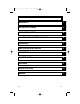
11-1 a b c d e f g h i G Br Br G Br R Br G Br Battery Pilot lamp (12V, 3.4W) Main switch Accelerator stop switch Back switch Buzzer Body ground Horn Horn sw.
UTILITY CAR OWNER’S/ OPERATOR’S MANUAL G21A 10/31/00 1PC - G21A O/M LIT196261100 *LIT196261100* USA Yamaha Motor Corp., USA Cypress, California made in YAMAHA MOTOR MANUFACTURING CORP. OF AMERICA LIT-19626-11-00 Printed in U.S.A.