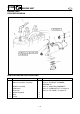
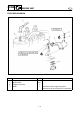
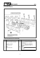
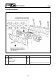
5-19
POWR
E
YPVS
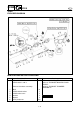
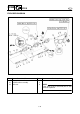
EXPLODED DIAGRAM
Step Procedure/Part name Q’ty Service points
7 Bolt (M4) 3
8 Circlip 5
9 Shaft 3 1
10 Shaft 2 1
11 Shaft 1 1
12 Washer 5
13 YPVS valve lever 3
NOTE:
During installation, align the hole a in
the YPVS shaft with the screw.
Not reusable