Reference Manual How to Use This Manual The MOTIF XF Reference Manual (in PDF format) is equipped with special features that are exclusive to electronic files, such as the Link function and the Search function which lets you jump to the desired page by clicking the page number of the specific term. n The MOTIF XF lets you select one of eight different color types (page 220). This manual uses the screen shots which are shown by setting the Color parameter to “Yellow” in the Utility mode.
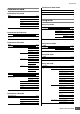
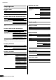
Function Tree Voice Edit mode (Drum Voice) Voice mode VOICE [VOICE] Drum Voice selection [EDIT] [COMMON] Voice Play mode VOICE Edit-Common Play ***** (Drum Voice name) Page # [F1] General 50 [F2] ARP Main [F1] Play 48 [F3] ARP Other [F2] Porta 50 [F4] Ctrl Set 51 [F6] Effect [SF6] INFO* [F3] EG/EQ 85 [SF2] Play Mode 85 [SF3] Other Page # [VOICE] [SF1] Name 85 85 85 86 [SF1] Connect 86 86 [F4] Arpeggio 52 [SF2] Ins A [F6] Effect 64 [SF3] Ins B [SF4] Reverb *Avail
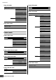
Function Tree Performance Store mode Performance mode Performance Store Performance Play mode PERF Page # [PERFORM] [STORE] Play 101 Page # [PERFORM] [SF6] INFO* 96 [F1] Play 95 [F2] Voice 97 [F3] EG 97 [F4] Arpeggio 98 [F6] Effect 107 *Available on certain displays.
Function Tree Song Job mode Pattern Edit mode Song Job Page # [SONG] [JOB] [F5] Track [F6] Song PATTERN Edit Page # [PATTERN] [EDIT] 01 Copy Track 162 02 Exchange Track 163 03 Mix Track 163 04 Clear Track 163 05 Normalize Play Effect 163 Pattern Job 06 Divide Drum Track 163 07 Put Track to Arpeggio 164 [PATTERN] [JOB] 08 Copy Phrase 164 01 Copy Song 165 02 Split Song to Pattern 165 03 Clear Song 165 Pattern Job mode Page # [F1] Undo/Redo [F2] Note Song Store mo
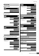
Function Tree SONG PATTERN Mixing mode [SONG] / [PATTERN] [MIXING] Normal Voice selection [F6] Vce Edit Element selection Mixing Play mode SONG PATTERN Mix Play [SONG] / [PATTERN] [MIXING] Edit-Elm [F2] Audio 191 [F5] Effect 193 [F4] Amplitude 198 Mixing Edit mode Edit-Common [SONG] / [PATTERN] [MIXING] [EDIT] [COMMON] Page # [F1] General [F2] Master FX [F4] Audio In 192 [SF2] Master FX 193 [SF3] Master EQ 193 [SF1] Output 193 [SF2] Connect 193 [SF3] Ins A 19
Function Tree Sampling Job mode Sampling mode Sample Job Sampling mode SAMPLE Page # [INTEGRATED SAMPLING] [JOB] Select [F2] Waveform Page # [VOICE] / [PERFORM] [INTEGRATED SAMPLING] [SONG] / [PATTERN] [INTEGRATED SAMPLING] 120 203 [F3] Other Sampling Record mode (Voice/Performance) SAMPLE Record 01 Copy 134 02 Delete 135 03 Extract 135 04 Transpose 135 05 Rename 135 01 Optimize Memory 135 02 Delete All 135 03 Copy to Flash Memory 135 Page # [VOICE] / [PERFORM] [
Function Tree Utility mode File mode Utility mode File mode UTILITY Page # [UTILITY] [F1] Play Page # 219 [SF1] Play 219 [SF2] Load 242 [SF2] Screen 220 [SF3] Rename 238 [SF3] Network 221 [SF4] Delete 238 [SF4] Auto Load 223 [SF5] New Dir 238 [F2] I/O [F3] Voice File [FILE] [SF6] INFO* [F1] File [SF1] Save 241 223 [F2] Mount 239 [SF1] Master FX 224 [F3] Format 240 [SF2] Master EQ 224 [F4] Audio [SF3] Arpeggio 225 [SF4] Tuning 225 [F4] Voice Audio [SF1] Outpu
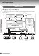
Basic Section Basic Structure The Seven Functional Blocks The MOTIF XF system consists of 7 main functional blocks: Tone Generator, Sampling, Audio Input, Sequencer, Arpeggio, Controller, and Effect.
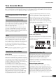
Tone Generator Block Tone Generator Block The tone generator block is what actually produces sound in response to the MIDI messages received from the Sequencer block, the Controller block, the Arpeggio block and from the external MIDI instrument via the MIDI IN connector or the USB connector. The structure of the tone generator block differs depending on the mode. A program that contains the sonic elements for generating a specific musical instrument sound is referred to as a “Voice.
Tone Generator Block normally (with the XA Control parameter settings “normal” and “legato”). Authentic note release sound Conventional synthesizers are not good at realizing the sound produced when the note of the acoustic instrument is released. The MOTIF XF realizes the sound produced when the note of the acoustic instrument is released, by setting the XA Control parameter of a certain Element to “key off sound.
Tone Generator Block Amplitude related parameters can be set in the Amplitude display (pages 79 and 89), Amplitude EG display (page 80) and Amplitude Scale display (page 81) of the Voice Edit mode. LFO (Low Frequency Oscillator) As its name suggests, the LFO produces a wave of a low frequency. These waves can be used to vary the pitch, filter or amplitude of each Element to create effects such as vibrato, wah and tremolo.
Sampling Block Maximum Polyphony Maximum polyphony refers to the highest number of notes that can be sounded simultaneously from the internal tone generator of the instrument. The maximum polyphony of this synthesizer is 128. When the internal tone generator block receives a number of notes exceeding the maximum polyphony, previously played notes are cut off. Keep in mind this may be especially noticeable with Voices not having decay.
Sequencer Block Section B Section C Phrase Song Chain This function allows Songs to be “chained” together for automatic sequential playback. For instructions on using this, see page 143. Song 01 Section A Song 22 Song 15 This is the basic MIDI sequence data in a track—and the smallest unit—used in creating a Pattern.
Sequencer Block Sequencer Block applied to both the Song and Pattern MIDI tracks and Audio tracks Basic Structure Basic Operation Basic Section Depending on the recording method, the Song/Pattern tracks (1 – 16) of this synthesizer are divided into two groups: MIDI tracks and Audio tracks. MIDI tracks are created by recording your keyboard performance in the Song Record mode/Pattern Record mode.
Arpeggio Block Arpeggio Block This block lets you automatically trigger musical and rhythmic phrases using the current Voice by simply pressing a note or notes on the keyboard. The Arpeggio sequence also changes in response to the actual notes or chords you play, giving you a wide variety of inspiring musical phrases and ideas—both in composing and performing. Four Arpeggio types can be played back at the same time even in the Song mode and Pattern mode.
Arpeggio Block Arpeggio Type Name How to use the Arpeggio Type List The Arpeggio Types are named according to certain rules and abbreviations. Once you understand these rules and abbreviations, you’ll find it easy to browse through and select the desired Arpeggio Types. The Arpeggio Type list in the Data List contains the following columns. 1 2 3 Main Sub ARP Category Category No.
Arpeggio Block To play the Arpeggio only when the note is pressed: Set the Hold parameter to “off” and the Trigger mode to “gate.” To continue the Arpeggio even if the note is released: Set the Hold parameter to “on.” To toggle the Arpeggio playback on/off whenever the note is pressed: Set the Trigger mode to “toggle.” The Hold parameter can be set to either “on” or “off.” n For the displays including the Hold and Trigger mode parameter, refer to “Arpeggio setting display” below.
Arpeggio Block Arpeggio playback types The Arpeggio playback features four main playback types as described below. Arpeggio Types for Normal Voices Arpeggio types (belonging to the categories except for the DrPC and Cntr) created for use of Normal Voices have the following three playback types. Playback only of the played notes The Arpeggio is played back using only the played note and its octave notes.
Arpeggio Block In the Voice Play mode, make sure that the [ARPEGGIO ON/OFF] button is lit, then play any note to trigger Arpeggio playback. 2 Try playing different notes and chords on the keyboard and listen to the Arpeggio play. Arpeggio playback responds in different ways, depending on the order of the notes you play and, of course, the selected Arpeggio Type. Also, try hitting the notes strongly and listen for the Accent Phrase feature.
Arpeggio Block Arpeggio playback/recording in the Pattern mode Arpeggios are also useful for creating Phrases, which can be used as the basic building blocks in making a Pattern. Create User Phrases as desired then assign them to the desired track in the Patch display (page 170). This section shows how to record a Arpeggio playback to a Pattern track. 1 Creating an original Arpeggio type In addition using the preset Arpeggios, you can also create your own original Arpeggio data.
Controller Block Controller Block This block consists of the keyboard, Pitch Bend and Modulation Wheels, Ribbon Controller, Knobs, Sliders and so on. The keyboard itself doesn’t generate sounds, but instead generates/transmits note on/off, velocity and other information (MIDI messages) to the synthesizer’s tone generator block when you play notes. The controllers also generate/transmit MIDI messages.
Effect Block Knobs and Sliders These eight knobs let you change various aspects of the Voice’s sound in real time—while you play. The eight sliders let you adjust the volume of the Voice Elements, Performance Parts and Mixing Parts. For more information about how to use the knobs and sliders in the respective modes, see page 46 (Voice mode), page 94 (Performance mode), and page 138 (Song/Pattern mode).
Effect Block Effect connection in each mode In the Voice mode 1 Voice 2 Element or Drum Key Element EQ 3 Insertion A 4 5 6 Master Effect Master EQ Insertion B Return Level Element 1 – 8 Drum Key C0 – C6 AD Part (set in the Utility mode) Reverb Chorus To Reverb Send Level 4 Determines the Send Level/Return Level to/ from the Reverb/Chorus and the signal level sent from the Chorus to the Reverb.
Effect Block 1 Sets the Part EQ parameters applied to each part in the EQ display (page 103) of Performance Part Edit. 3 Selects the Master Effect type and sets the Effect parameters in the Master Effect display (page 104) of Performance Common Edit. 2 Determines the Send Level/Return Level to/ from the Reverb/Chorus and the signal level sent from the Chorus to the Reverb. 4 Sets the Master EQ parameters in the Master EQ display (page 105) of Performance Common Edit.
Effect Block Description Reverb emulating the acoustics of a concert hall derived from the Yamaha SPX1000. REV-X ROOM – – Reverb emulating the acoustics of a room using the REV-X technology. R3 ROOM – – Reverb emulating the acoustics of a room using the algorithm derived from the Yamaha ProR3. SPX ROOM Reverb emulating the acoustics of a room derived from the Yamaha SPX1000. R3 PLATE – – Reverb emulating a metal plate using the algorithm derived from the Yamaha ProR3.
Effect Block Compressor Effect Type Compressor is an effect commonly used to limit and compress the dynamics (softness/loudness) of an audio signal. When used with gain to boost the overall level, this creates a more powerful, more consistently high-level sound. Compression can be used to increase sustain for electric guitar, smooth out the volume of a vocal, or bring a drum kit or rhythm pattern further up-front in the mix.
Effect Block Parameter name Descriptions AEG Phase Offsets the phase of the AEG. AM Depth Determines the depth of the amplitude modulation. AM Inverse R Determines the phase of the amplitude modulation for the R channel. VCM Auto Wah, VCM Touch Wah, VCM Pedal Wah AM Speed Determines the amplitude modulation speed. AM Wave Selects the wave for modulating the amplitude. AMP Type Selects the amplifier type to be simulated.
Effect Block Parameter name Descriptions Descriptions Determines the depth of the modulation generated via the rotation of the horn. High Threshold Determines the minimum input level at which the effect is applied to the high frequencies. Drive Rotor Determines the depth of the modulation generated via the rotation of the rotor. Horn Speed Fast Determines the speed of the horn when the slow/fast switch is set to “fast.
Effect Block Determines the cutoff frequency of the low pass filter applied to the modulated sound. Mod LPF Resonance Determines the resonance of the low pass filter for the modulated sound. Mod Mix Balance When “Noisy” is selected, this parameter determines the mix balance of the modulated element. When “Tech Modulation” is selected, this parameter determines the volume of the modulated sound. Mod Speed Determines the modulation speed. Mod Wave Type Selects the wave type for modulation.
About MIDI About MIDI MIDI (Musical Instrument Digital Interface) is a standard which allows electronic musical instruments to communicate with each other, by sending and receiving compatible Note, Control Change, Program Change and various other types of MIDI data, or messages. This synthesizer can control other MIDI devices by transmitting note related data and various types of controller data.
About MIDI Pitch bend events are generated by pitch bend wheel operation and define continuous changes in pitch. The value (-8192 – +0000 – +8191) is a numerical representation of pitch bend wheel position. The bar graph to the right is a graphic representation of the value. Program Change (PC) produces maximum portamento time. Portamento is only produced when Portamento (Control Number 065) is ON.
About MIDI Decay Time (Control Change 075) Omni Mode Off (Control Number 124) Adjusts the decay time of the Voice AEG. The decay time is adjusted by using the data range of 0 – 127 as an offset value with a display range of -64 – +63 which is added to the Voice data. Performs the same operation as when an All Notes Off message is received. The receive channel is set to 1. Omni Mode On (Control Number 125) Specifies the reverb effect send level.
About MIDI MSB (101), RPN LSB (100), and Data Entry MSB (6). In the MOTIF XF, Data Entry LSB (38) is added to this and the resulting group of control change events is handled as one. Once an RPN is specified, the following data entry message received on the same channel is processed as the value of that RPN. Prevent operational errors by transmitting a Null message (7FH, 7FH) after using these messages to perform a control operation.
Internal Memory Internal Memory As you use the MOTIF XF, you will create many different kinds of data, including Voices, Performances, Songs, and Patterns. This section describes how to maintain the various types of data and use the memory devices/media for storing them. Internal Memory Below are explanations of the basic terms related to memory. Refer to the diagram on the next page for details about data handled via the following memory types.
Internal Memory Memory Structure This diagram details the relationship among the functions of the MOTIF XF and the internal memory and external devices such as USB storage device and computer.
Basic Operation Moving the Cursor Use these four buttons to navigate the display, moving the cursor around the various selectable items and parameters in the screen. When selected, the relevant item is highlighted (the cursor appears as a dark block with inverse characters). You can change the value of the item (parameter) at which the cursor is located by using the data dial, [INC/YES] and [DEC/NO] buttons. mainly to call up the INFO and LIST displays).
Basic Operation This indicates that you can call up the List by pressing the [SF6] LIST button. The List appears. You can select one from this List. Character List Editing area Several parameters let you set a key range or velocity range for a function—for example, in setting up a keyboard split—by specifying certain note values. You can use the [INC/YES] and [DEC/NO] buttons or data dial to set these parameters, or you can directly enter the values from the keyboard by pressing the appropriate keys.
Connections n For the external connections depicted below, you will also need speakers or headphones to listen to the sound. For details, refer to the Owner’s Manual. Connecting External MIDI Instruments With a standard MIDI cable (available separately), you can connect an external MIDI instrument, and control it from the MOTIF XF. Likewise, you can use an external MIDI instrument (such as a keyboard or sequencer) to control the sounds of the MOTIF XF.
Connections Controlling another MIDI device via MIDI THRU The playback data of an external MIDI sequencer is used to play the sounds of another MIDI instrument (connected to the MIDI THRU connector) along with the MOTIF XF. The MIDI THRU connector simply redirects any received MIDI data (via MIDI IN) to connected instrument.
Connections Controlling an MTR by using MMC transmitted from the MOTIF XF You can control the start/stop and fast forward/rewind of an MMC-compatible MTR from the SEQ TRANSPORT buttons on the front panel of this synthesizer, outputting MMC messages via MIDI. MIDI IN MIDI OUT MOTIF XF MIDI IN MIDI OUT AW2400, etc. n MMC (MIDI Machine Control) allows remote control of multitrack recorders, MIDI sequencers, etc.
Connections Connecting a USB ASCII keyboard You can connect an ASCII keyboard to the instrument via its USB TO DEVICE terminal. This conveniently allows you to type in Voice names, Song names, file names, and other alphanumeric text, to enter values for parameters that would normally require the numeric-keypad function, and to operate the instrument using function keys and shortcut keys.
Connections setting these parameters, consult your network administrator or provider. For information on the other parameters, refer to the explanation of the Network display (page 221) in the Utility mode. Network Settings After the LAN connection is completed, you should set the network related parameters to make the connection active. Once the MOTIF XF has been connected to the network, files can be saved or loaded between the MOTIF XF and the computer connected to the same network.
Connections the password as illustrated below. Here, enter the User Account of your computer to the User Name box, enter the password of your computer to the Password box, then press the [ENTER] button so that the access between the MOTIF XF and the computer is established. The shared directories of the selected computer are listed in the Sharing Point box (*).
Reference Playing the Keyboard in the Voice Play Mode Voice mode The Voice mode is used for selecting, playing, and editing a desired Voice. The Voice Play mode is the main ‘portal’ by which you enter the Voice mode, and it is here where you select and play a Voice. Some of the Voice settings can also be edited in this mode. To call up the Voice Play display and enter the Voice mode, simply press the [VOICE] button. Performance mode 3 Selecting a Voice Sampling mode 1 Song mode 4 Select a Voice.
Playing the Keyboard in the Voice Play Mode Select your favorite Voice. Find the desired Voice by following the instructions on the Owner’s Manual. Register the Voice to the Favorite Category. Press the [F5] button to register the Voice and turn on the Favorite Switch. A checkmark appears in the box to the left of the Voice name, indicating that the Voice has been included in the Favorite Category.
Playing the Keyboard in the Voice Play Mode Using Knobs and Control Sliders Voice mode Performance mode Sampling mode 1 One of the more powerful performance features of the MOTIF XF is its extensive set of real-time controls— especially the Knobs and Control Sliders. These let you adjust a variety of parameters for the current Voice, such as effect depth, attack/release characteristics, tonal color, and others.
EQ HIGH (EQ High Gain) Increases or decreases the EQ High Gain (page 51) to change the current Voice. Knob 6 PAN Adjusts the stereo pan position of the current Voice (page 56). Moving Knobs changes the Arpeggio related parameters in the Voice Common Edit mode. This operation is available when the Arpeggio function is turned on. Knob 1 SWING Adjusts the swing feel of the Arpeggio playback (page 60). Turning it clockwise increases the swing feel whereas turning it counter-clockwise decreases it.
Playing the Keyboard in the Voice Play Mode Voice mode Performance mode standard pitch. The current octave setting is shown at the top right of the display. You can instantly restore standard pitch (0) by simultaneously pressing both the OCTAVE [UP] button and the OCTAVE [DOWN] button (both lamps turn off). The lamp status of the OCTAVE [DOWN]/[UP] button lets you recognize at a glance the current octave setting. When set to one octave down or up, the corresponding lamp lights.
Voice Number A01 – 16 001 – 016 n This menu is available only for the top display of the Voice mode. ! [F1] Play (Voice Play) Pressing this button returns from the previous display to the Voice Play display. B01 – 16 017 – 032 C01 – 16 033 – 048 @ [F2] Porta (Portamento) D01 – 16 049 – 064 E01 – 16 065 – 080 Pressing this button calls up the Portamento display (page 50).
Playing the Keyboard in the Voice Play Mode 8 Portamento Voice information—[SF6] INFO (Information) Indicates the Portamento Switch on/off status (page 50) of the current Voice. Voice mode This display indicates the information of the current Voice. Settings cannot be changed here. Performance mode Indicates the Effect settings (for Insertion A, Insertion B, Reverb and Chorus) of the current Voice. 6 8 n Parameters 6, 7 and 8 are not available when the Drum Voice is selected.
Playing the Keyboard in the Voice Play Mode Determines the speed of filter variation from the time a note is played until the maximum initial level of the Cutoff Frequency is reached. You can change the tonal color or timbre of the sound by editing the EG/EQ settings for all Elements making up the Voice. The EG settings made here will be applied to the same parameters in the Amplitude EG display (page 80) and Filter EG display (page 76) for all Elements as an offset.
Playing the Keyboard in the Voice Play Mode Gain Determines the level gain for the Frequency (set above), or the amount the selected frequency band is attenuated or boosted. The higher the value, the greater the Gain. The lower the value, the lesser the Gain. Settings: -12.00 dB – +0.00 dB – +12.00 dB Voice mode Q (Bandwidth) Determines the Q (bandwidth) for the Mid band. The higher the value, the smaller the bandwidth. The lower the value, the wider the bandwidth. Performance mode Settings: 0.7 – 10.
Editing Normal Voices 1 Press the [VOICE] button to enter the Voice Play mode. Select a Normal Voice to be edited. 2 3 Press the [EDIT] button to enter the Voice Edit mode. Call up the desired Edit display, Common Edit or Element Edit. To call up the Common Edit display, press the [COMMON EDIT] button. To call up the Element Edit display, press one of the Number buttons [1] – [8] to select the Element to be edited. Indicates this display is in the Common Edit mode.
Editing a Normal Voice When the [E] indicator is shown in the Voice Play mode, press the [EDIT] button to enter the Voice Edit mode then press the [EDIT] button again to call up the Compare mode. Convenient functions for editing Voices Compare indicator (sound prior to editing) Voice mode Switching an Element on/off Performance mode In the Voice Edit mode, you can always use the number buttons [1] – [8] to select an Element. The [1] – [8] buttons indicate the Element being edited.
Editing a Normal Voice Common Edit parameters [VOICE] Normal Voice selection [EDIT] [COMMON EDIT] About the asterisk (*) marks Keyboard FM Piano Clavi Synth Arpeggio Organ Or Tone Wheel Combo Pipe Synth Arpeggio Guitar Gt Acoustic Electric Clean Electric Distortion Synth Arpeggio Bass Bs Acoustic Electric Synth Arpeggio Strings St Solo Ensemble Pizzicato Synth Arpeggio Brass Br Solo Brass Ensemble Orchestra Synth Arpeggio — Sax / Woodwind SW Saxophone Flute Wo
Editing a Normal Voice 2 Pan* Determines the stereo pan position of the Voice. You can also adjust this parameter using the PAN knob on the front panel. Micro Tuning List Micro Tuning No. Voice mode 1 Performance mode 3 Note Shift* Sampling mode 1 4 PB Range Upper (Pitch Bend Range Upper)* 5 PB Range Lower (Pitch Bend Range Lower)* Song mode Mixing mode Reference Pattern mode Determines the maximum Pitch Bend range in semitones.
Editing a Normal Voice Voice mode Performance mode 2 3 4 5 6 multi Settings: on, off @ Portamento Time* Determines the pitch transition time when Portamento is applied. The effect of the parameter differs depending on the settings of the Portamento Time Mode ($). Higher values result in a longer pitch change time. Settings: 0 – 127 # Portamento Mode Determines how Portamento is applied to your keyboard performance.
Editing a Normal Voice Arpeggio settings—[F2] ARP Main (Arpeggio Main) Voice mode This display determines the basic settings of the Arpeggio. Keep in mind that parameters Bank (!) through Gate Time Rate Offset (^) have five settings which can be edited in each of the [SF1] ARP1 through [SF5] ARP5 displays. For details about Arpeggio, see page 15.
% Velocity Rate Adjusts the velocity of the Arpeggio notes. The Arpeggio plays back at the preset velocities included in the Arpeggio sequence data. Determines the offset value by which the Arpeggio notes will be shifted from their original velocities. If the resultant velocity value is less than zero it will be set to 1, and if the resultant velocity is greater than 128 it will be set to 127. This parameter can be changed via the Knob directly.
Editing a Normal Voice Voice mode 3 Quantize Strength 9 Trigger Mode Sets the “strength” by which note events are pulled toward the nearest quantize beats. A setting of 100% produces exact timing set via the Quantize Value parameter above. A setting of 0% results in no quantization. A setting of 50% results in the note events being pulled halfway between 0% and 100%. This parameter can be changed via the Knob directly.
Editing a Normal Voice Indicates the Knobs printed “ASSIGN 1” and “ASSIGN 2” with the TONE 1 lamp turned on. 3 4 n Regarding “Insertion Effect A Parameter 1 – 16,” “Insertion Effect B Parameter 1 – 16” and “Insertion Effect L Parameter 1 – 32” described in the Control List, the actual parameter names of the selected Effect type are shown on the display. If one of these names is shown, no function is assigned to that parameter.
Editing a Normal Voice 5 Graph (Indication only) 4 Phase The horizontal axis indicates the value generated via the Source of the selected Set, whereas the vertical axis indicates the degree to which the Destination parameter is affected. Determines the starting phase point for the LFO Wave when it is reset.
Editing a Normal Voice each-on 1st-on The LFO resets with each note you play and starts a waveform at the phase specified by the Phase parameter (above). If you play a second note while the first is being held, the LFO continues cycling according to the same phase as triggered by the first note. In other words, the LFO only resets if the first note is released before the second is played.
Editing a Normal Voice to 0, and if the resultant Control Depth value is greater than 127 it will be set to 127. Settings: 0 – 127 n You can use the [SF5] Random button to call up the base wave at random. Each time you press the [SF5] Random button, a different LFO wave appears on the display randomly. 2 Slope 5 LFO Phase Offset Voice mode Determines the offset values of the Phase parameter in the [SF1] Wave display for the respective Elements.
5 Chorus (Chorus Category/Type)* Determines which Insertion Effect (A or B) is used to process each individual Element. The “thru” setting lets you bypass the Insertion Effects for the specified element. When INSERTION CONNECT (2) is set to “ins L,” the signal from each Element is output to the Insertion L regardless of the setting here. Selects a Chorus Effect type after selecting a category.
Editing a Normal Voice 1 Category 2 Type Effect Parameter settings—[SF2] Ins A, [SF3] Ins B, [SF4] Reverb, [SF5] Chorus Voice mode From the Category column, you can select one of the Effect Categories each of which contains similar Effect types. From the Type column, you can select one of the Effect Types listed in the selected Category. From these displays, you can set the Effect related parameters when the INSERTION CONNECT parameter is set to “parallel” or “ins A FB” or “ins B F A.
Editing a Normal Voice 8 Formant Shift Determines the microphone sound level, which is to be input to the Vocoder. Settings: Thru, Vocoder Settings: 0 – 127 2 Vocoder Attack ! Inst Input Level Determines the attack time of the Vocoder sound. The higher the value, the slower the attack. Determines the level of the keyboard performance sound, which is to be input to the Vocoder.
Editing a Normal Voice Vocoder structure Voice mode Performance mode The human voice consists of sounds generated from the vocal cords, and filtered by the throat, nose and mouth. These resonant sections have specific frequency characteristics and they function effectively as a filter, creating many formants (harmonic content). The Vocoder effect extracts the filter characteristics of the voice from the microphone input and recreates the vocal formants by the use of multiple band pass filters.
Editing a Normal Voice Element Edit parameters [VOICE] Normal Voice selection [EDIT] [1] – [8] n Depending on the selected parameter, the LIST icon is shown at the tab menu corresponding to the [SF6] button. In this condition, you can call up the list by pressing the [SF6] LIST button, then select the desired item from the list. For details, see page 37. 1 Element Switch* Determines whether the currently selected Element is on or off.
Editing a Normal Voice key off sound When this is selected, the Element will sound each time you release the note. wave cycle Voice mode When this is selected for multiple Elements, each Element sounds alternately according to its numerical order each time you play a note. (In other words, playing the first note will sound Element 1, the second note Element 2, and so on.) wave random When this is selected for multiple Elements, each Element will sound randomly each time you press the note.
Editing a Normal Voice Determines the lowest and highest notes of the keyboard range for each Element. The selected Element will sound only when you play notes within this range. If you specify the highest note first and the lowest note second, for example “C5 to C4,” then the note range covered will be “C -2 to C4” and “C5 to G8.” Settings: C -2 – G8 n You can also set the Key directly from the keyboard, by holding down the [SF6] INFO button and pressing the desired key. For details, see page 37.
Editing a Normal Voice 6 Pitch Key Follow Pitch Voice mode Determines the sensitivity of the Key Follow effect (the pitch interval of adjacent notes), assuming the pitch of the Center Key (7) as standard. At +100% (the normal setting), adjacent notes are pitched one semitone (100 cents) apart. At 0%, all notes are the same pitch specified as the Center Key. For negative values, the settings are reversed.
Editing a Normal Voice High Velocity Low Velocity Fast pitch transition Slow pitch transition Determines the range over which the pitch envelope changes. A setting of 0 will cause the pitch not to change. The farther from 0 the value is, the larger the pitch range. For negative values, the pitch change is reversed. Settings: -64 – +0 – +63 % EG Time Segment Determines the part of the Pitch EG which the EG Time Velocity Sensitivity ($) affects.
Editing a Normal Voice & Center Key About Filter Types Determines the central note or pitch for the EG Time Key Follow (^). When the Center Key note is played, the PEG behaves according to its actual settings. Settings: C -2 – G8 Voice mode EG Time Key Follow and Center Key Positive value Performance mode Negative value Faster speed This is a Filter type that only passes signals below the Cutoff Frequency. The sound can be brightened by raising the cutoff frequency of the filter.
Editing a Normal Voice BPF6 Dual BEF The combination of a -6 dB/oct HPF and LPF. Two -6 dB/oct band-elimination filters connected in parallel. Level Level Cutoff range Range passed Cutoff range Distance (9) Cutoff range Frequency Performance mode Only the lower cutoff frequency is set directly on the display. Combination Type Filter Level Cutoff range Cutoff range Width (4) This type is a combination of two different filter types.
Editing a Normal Voice Voice mode Performance mode Sampling mode 1 4 Resonance*/ Width 9 Distance This parameter’s function varies according to the selected Filter Type. If the selected filter is an LPF, HPF, BPF (excluding the BPFw), or BEF, this parameter is used to set the Resonance. For the BPFw, it is used to adjust the frequency bandwidth Resonance is used to set the amount of Resonance (harmonic emphasis) applied to the signal at the cutoff frequency.
Editing a Normal Voice 8 Decay 1 Level Cutoff Frequency Determines the level which the cutoff frequency reaches from the Attack Level after the Decay1 time elapses. 7 Attack Level Determines the final cutoff frequency reached after the note is released. ! EG Depth The Time parameters let you set the time between the adjoining points of the level parameters below. A higher value results in a longer time until reaching the next level.
Editing a Normal Voice $ EG Time Velocity Sens (EG Time Velocity Sensitivity) Voice mode Performance mode Determines how the FEG transition time (speed) responds to velocity, or the strength with which the note is pressed. When this is set to a positive value, high velocities result in a fast FEG transition speed while low velocities result in a slow speed, as shown below.
Editing a Normal Voice Break Point Offset 2 3 4 Settings: 0 – 127 C#1 D#2 C3 A4 -4 +10 +17 +4 Cutoff frequency Raises or lowers the level specified at the Level Velocity Sensitivity (2). A setting of 64 results in the original values of the Level Velocity Sensitivity (2) being used. Settings above 64 will raise the level specified at the Level Velocity Sensitivity (2). Settings below 64 will reduce the level.
Editing a Normal Voice 8 Alternate Pan Time* Determines the amount by which the sound is panned alternately left and right for each note you press, assuming the pan position set above as center. Higher values increase the width of the Pan range. The Time parameters let you set the time between the adjoining points of the level parameters below. A higher value results in a longer time until reaching the next level.
Settings: -64 – +0 – +63 $ Center Key Determines the central note for the EG Time Key Follow (#). When the Center Key note is played, the AEG behaves according to its actual settings. Settings: C -2 – G8 n You can also set the Key directly from the keyboard, by holding down the [SF6] KBD button and pressing the desired key. For details, see page 37.
Editing a Normal Voice Voice mode 1 – 4 Break Point 1 – 4 1 Wave Determines the four Break Points by specifying the note numbers respectively. Selects the Wave and determines how the LFO waveform modulates the sound. Settings: C -2 – G8 Settings: saw, triangle, square n You can also set the Break Point directly from the Keyboard, by holding down the [SF6] KBD button and pressing the desired key. See “Basic Operation” on page 37.
Editing a Normal Voice Settings: 1 EQ Type 2 4 6 Boosts the entire band of the selected Element by +6dB, +12dB, and +18dB respectively. thru If you select this, the equalizers are bypassed and the entire signal is unaffected. When the EQ Type is set to “2 Band” This is a “shelving” equalizer, which combines separate high and low frequency bands. 2 Low Frequency Determines the center frequency. Settings: 139.7 Hz – 12.
Editing a Drum Voice Voice mode “Editing” refers to the process of creating a Voice by changing the parameters that make up the Voice. This can be done in Voice Edit, a sub mode within the Voice mode. In this section, we’ll show you how to edit a Drum Voice. To enter the Drum Voice Edit mode, press the [VOICE] button to enter the Voice mode, select a Drum Voice, then press the [EDIT] button.
Editing a Drum Voice This is the same as in Normal Voice Common Edit. See page 58. Naming the edited Voice—[SF1] Name This is the same as in Normal Voice Common Edit. See page 55. Play Mode Settings such as Micro Tuning and Mono/Poly—[SF2] Play Mode This is the same as in Normal Voice Common Edit. See page 55. Other settings—[SF3] Other This is the same as in Normal Voice Common Edit. See page 57.
Editing a Drum Voice Voice mode Performance mode Controller settings—[F4] Ctrl Set (Controller Set) n When the Insertion Effect Out parameter (1) is set to “Ins A” or “Ins B,” you can determine the level of the Drum Key sound (output from Insertion Effect A or B) that is sent to the Reverb effect by setting the value of the Insertion Reverb Send parameter indicated only in this case. This is the same as in Normal Voice Common Edit. See page 61.
Editing a Drum Voice Key Edit parameters [VOICE] Drum Voice selection [EDIT] Key selection $ % ^ & n Depending on the selected parameter, the LIST icon is shown at the tab menu corresponding to the [SF6] button. In this condition, you can call up the list by pressing the [SF6] LIST button, then select the desired item from the list. For details, see page 37. 1 Key* Determines the Drum Key to be edited. You can select the desired percussion instrument by pressing the note.
Editing a Drum Voice 9 Alternate Group* LCD Voice mode Determines the Alternate Group to which the key is assigned. In a real drum kit, some drum sounds cannot physically be played simultaneously, such as open and closed hi-hats. You can prevent keys from playing back simultaneously by assigning them to the same Alternate Group. Up to 127 Alternate Groups can be defined. You can also select “off” here if you wish to allow the simultaneous playback of sounds.
Editing a Drum Voice 1 2 3 4 3 4 5 6 7 9 8 1 Level* Determines the output level of the Drum Key. 2 Cutoff Velocity Sens (Cutoff Velocity Sensitivity)* Determines how the Cutoff Frequency responds to velocity, or the strength with which you play notes. Positive settings will cause the Cutoff Frequency to rise the harder you play the keyboard. A setting of 0 will cause the Cutoff Frequency not to change depending on velocity.
Editing a Drum Voice Amplitude EG Using the AEG, you can control the transition in volume from the moment the sound starts to the moment it stops. Level (Volume) Attack Level Voice mode 9 Decay1 Level 0 Performance mode Attack Time 6 Decay1 Time 7 Pressing the key (Key on) Time Decay2 Time 8 Releasing the key (Key off) Sampling mode 1 Time* Song mode The Time parameters let you set the time between the adjoining points of the level parameters below.
Voice Job—Convenient Functions 4 Press the [ENTER] button. (The display prompts you for confirmation.) When a Normal Voice is selected: To cancel the Job, press the [DEC/NO] button. Press the [INC/YES] button to execute the Job. After the Job has been completed, a “Completed” message appears and operation returns to the original display. 6 2 3 4 Sampling mode 2 5 Mixing mode 1 Press the [VOICE] button to return to the Voice Play mode.
Voice Job—Convenient Functions When a Drum Voice is selected: 1 Voice mode 2 5 6 7 Determines the Bank and the Voice number to be copied. The available parameters will vary depending on the type of Voice currently selected (Normal/Drum). This parameter cannot be set when the Current Voice (2) is turned on. 2 Current Voice Performance mode When this is set to on, the currently selected Voice (the one you are editing now) is selected as source.
lights), then use the appropriate Number buttons [1] – [4] to mute and unmute the desired Part. Selecting a Performance Turning specific Parts on/off (Mute function) The SOLO lamp lights, indicating that Solo is enabled. 2 Press any of the Number buttons [1] – [4]. The lamp of the pressed button will flash and only the corresponding Part will be sounded. Press any other Number button to change the solo Part. n To exit from the Mute and Solo conditions, press the [TRACK] or [PERFORMANCE CONTROL] button.
Playing in the Performance Mode Turning Arpeggio playback on/off for each Part You can turn Arpeggio playback on or off for each Part of the Performance as described below. Voice mode 2 Performance mode 1 1 Press the [PERFORMANCE CONTROL] button. One of the more powerful performance features of the MOTIF XF is its extensive set of real-time controls— especially the Knobs and Control Sliders.
Playing in the Performance Mode Changing a Part to be controlled You can change a Part to be controlled by Knob operations via the following instructions. 1 Turn the [PERFORMANCE CONTROL] lamp on by pressing the [SELECTED PART CONTROL] button to call up the Control Function window. 2 Select the desired Part by pressing the [1] – [4] buttons and [COMMON EDIT] button. By pressing the [COMMON EDIT] button, Knob operations except for “ASSIGN 1” and “ASSIGN 2” will be applied to all four Parts.
Playing in the Performance Mode Voice mode 3 Category (Main Category ) % [F6] Effect Indicates the Category of the selected Performance. “Category,” consisting of Main Category and Sub Category, is a keyword that indicates the instrument characteristics or the type of sound. Each Performance can be registered to a Main Category and its Sub Category. The Category settings can be edited in the General display (page 102) of the Performance Common Edit mode.
Playing in the Performance Mode 4 Name Indicates the Bank, Number, Main Category 1/2, and name of the Voice which is assigned to each Part. 6 Effects Indicates Reverb and Chorus settings of the selected Performance. This display lets you set the EG (Envelope Generator) and Filter. The settings made here will be applied to the same parameters in the EG display (page 115) of Part Edit as offset.
Playing in the Performance Mode Arpeggio settings—[F4] Arpeggio Voice mode Performance mode Sampling mode 1 This display determines the basic settings of the Arpeggio. There are two types of parameters: Common parameters (Common Switch, Tempo and Sync Quantize Value indicated at the top of the display) and Part parameters (others). As for the Part parameters, five different Arpeggio types can be assigned to each of the four Parts, and are selectable with the [SF1] – [SF5] buttons.
1 Sequencer Mode ! [SF1] ARP1 – [SF5] ARP5 (Arpeggio 1 – 5) Determines to which destination (Song or Pattern) your Performance playing will be recorded. The Arpeggio types are assigned to the Sub Function buttons with the 8th note icon on the display tab. You can call them up by pressing these buttons any time while recording. The Arpeggio Type can be set in the Arpeggio display (page 98).
Editing a Performance Voice mode The Performance Edit mode lets you create your own original Performances—containing up to four different Parts (Voices)— by editing the various parameters. To enter the Performance Edit mode, press the [PERFORM] button to enter the Performance mode, then press the [EDIT] button. Performance mode Common Edit and Part Edit Call up the desired display.
Editing a Performance Storing the created Performance Press the [STORE] button to call up the Performance Store window. 2 Set the destination for storing the Performance. 3 Compare function The Compare function lets you switch between the justedited Performance and its original, unedited condition, allowing you to hear how your edits affect the sound. 1 In the Performance Edit mode, press the [EDIT] button to call up the Compare mode.
Editing a Performance Common Edit parameters [PERFORM] Performance selection [EDIT] [COMMON EDIT] Voice mode Common Edit lets you edit the parameters common to all Parts of the selected Performance. This covers all parameters of the Common Edit. About the asterisk (*) marks Performance mode For users who are new to editing and may be confused by the large amount of parameters, the most basic and easy-to-understand parameters are conveniently marked with asterisks in this section.
Editing a Performance Portamento settings—[SF2] Porta 1 2 Frequency Determines the center frequency. Frequencies around each of three points are attenuated/boosted by the Gain setting below. Higher values produce a higher frequency. 3 1 Low Frequency Determines the center frequency of the lower EQ band. Voice mode Settings: -64 – +63 Determines the pitch transition time when Portamento is applied. You can adjust Portamento time for the Voice assigned to each Part as offset.
Editing a Performance Other settings—[SF4] Other From this display, you can set the control functions for the Knobs, and the up/down range for the Pitch Bend wheel. Voice mode 1 5 2 3 6 Performance mode 4 1 Knob Control Assign Sampling mode 1 Determines which lamp among the TONE 1, TONE 2, ARP FX, REVERB, CHORUS and PAN is turned on when selecting a Performance. This setting can be stored for each Performance.
Editing a Performance This type of EQ shape lets you attenuate/boost the signal at frequencies above or below the specified Frequency setting. Gain Voice mode 0 EQ High + Frequency 0 Settings: on, off – Frequency peak (Peaking type) This type of EQ shape lets you attenuate/boost the signal at the specified Frequency setting. 3 Preset + You can set various parameters in order to change how the sound is affected by the selected Effect type.
Editing a Performance Audio In settings—[F4] Audio In You can set parameters related to audio input from the A/D INPUT connector and the IEEE1394 connector. Voice mode n The FW settings (FW1 –14) are available only when the optional FW16E is installed. Output jacks FW OUTPUT 1 : Stereo/Mono Mono : : FW14 FW OUTPUT 14 Mono ins L Internal Vocoder Module Mono (A/D input only) n You can call up the list and select the desired item by pressing the [SF6] LIST button. For details, see page 37.
Editing a Performance Ins A F B (A to B) Signals processed with the Insertion Effect A will be sent to the Insertion Effect B and signals processed with the Insertion Effect B is sent to Reverb and Chorus. page 27 for details about the Effect parameters. Refer to the separate Data List for information on the parameters for each Effect type. Ins B F A (B to A) 5 2 3 2 6 7 4 n Depending on the selected parameter, the LIST icon is shown at the tab menu corresponding to the [SF6] button.
Editing a Performance 4 Chorus Return Determines the Return level of the Chorus Effect. Settings: 0 – 127 Reverb and Chorus Settings—[SF3] Reverb, [SF4] Chorus 5 Chorus Pan Voice mode 1 2 Determines the pan position of the Chorus effect sound. Settings: L63 (far left) – C (center) – R63 (far right) 6 Reverb Return 3 Performance mode Determines the Return level of the Reverb Effect. Settings: 0 – 127 7 Reverb Pan Sampling mode 1 Determines the pan position of the Reverb effect sound.
Editing a Performance Part Edit parameters The display for the currently selected Part 5 6 7 4 8 9 ) ! @ # $ % 1 Part Switch* Settings: off (inactive), on (active) 2 Bank* 3 Number* Determines the Voice assigned to the current Part by specifying the Voice Bank and Number. The display for all four Parts of the current Performance n You can call up the list and select the desired item by pressing the [SF6] LIST button. For details, see page 37. 4 Param.
Editing a Performance copied when a Drum Voice is selected. However, these parameters are copied when a Normal Voice is selected. Settings: fingered, fulltime fingered Settings: off (not copied), on (copied) Portamento is only applied when you play legato (playing the next note before releasing the previous one). 5 Volume* fulltime Voice mode Determines the volume for each Part. Use this parameter to adjust the balance between the current Part and other Parts.
Editing a Performance 3 Dry Level Other Settings—[SF3] Other Sampling mode 1 4 Output Select 1 2 Determines the specific output(s) for the individual Part. You can assign each individual Part’s Voice to be output from a specific hardware output jack on the rear panel. 3 4 Song mode Settings: 0 – 127 Settings: See the table below.
Editing a Performance Voice mode Performance mode 4 Velocity Sens Depth Offset (Velocity Sensitivity Depth Offset) 1 Switch* Determines the amount by which played velocities are adjusted for the actual resulting velocity effect. This lets you raise or lower all velocities by the same amount—allowing you to automatically compensate for playing too strongly or too softly. If the result is 1 or less, the value is set to 1. If the result is higher than 127, the value is set to 127.
Editing a Performance currently assigned Voice is maintained. The name of the Voice registered to the Arpeggio Type is shown at the right side. ) Output Octave Shift Specifies the maximum Arpeggio range in octaves. Settings: -10 – +10 Determines how the Arpeggio plays back when playing the keyboard. Settings: sort, thru, direct, sort+direct, thru+direct sort When you play specific notes (for example, the notes of a chord), the same sequence plays, no matter what order you play the notes.
Editing a Performance Arpeggio settings—[F3] ARP Other (Arpeggio Other) Voice mode By changing the timing and velocity of the notes, you can change the rhythmic “feel” of the Arpeggio playback. Performance mode 1 2 3 4 5 6 7 % ^ & 8 9 ) ! @ # $ Sampling mode 1 n The Four-Part display cannot be called up from this display. 1 Unit Multiply Song mode Pattern mode Mixing mode Reference Adjusts the Arpeggio playback time based on tempo.
Editing a Performance # Random SFX Velocity Offset 3 Determines the offset value by which the Random SFX notes will be shifted from their original velocities. If the resultant velocity value is less than zero it will be set to 1, and if the resultant velocity is greater than 128 it will be set to 127. Settings: -64 – +0 – +63 $ Random SFX Key On Control When this is set to “on,” the Random SFX special sound is played with the pre-programmed velocity.
Editing a Performance Decay (Decay Time) 1 Frequency Determines how fast the Cutoff Frequency falls from maximum attack level to the sustain level. Determines the center frequency. Frequencies around this point are attenuated/boosted by the Gain setting below. Higher values produce higher frequencies. Release (Release Time) Voice mode Performance mode Sampling mode 1 Determines how fast the Cutoff Frequency falls from the sustain level to zero when a note is released. Settings: Depth 50.1 Hz – 2.
Performance Job—Convenient Functions Press the [ENTER] button. (The display prompts you for confirmation.) Press the [INC/YES] button to execute the Job. After the Job has been completed, a “Completed” message appears and operation returns to the original display. 6 Press the [PERFORM] button to return to the Performance Play mode. NOTICE Even if you execute the Job, selecting a different Performance or turning the power off without storing will erase the Performance data.
Performance Job—Convenient Functions Performance Copy function—[F3] Copy Voice mode Copying parameter settings from another Performance—[SF1] Part Performance mode This convenient operation lets you copy Common Edit and Part Edit settings of a certain Performance to the currently edited Performance. This is useful if you are creating a Performance and wish to use some parameter settings of another Performance.
NOTICE The recorded (edited) Sample data will be lost when turning the power off. Before turning off the power, you should always copy the Sample data to the optional Flash Memory Expansion Module (page 34), or save the Sample data to a USB storage device or a computer connected to the same network as the MOTIF XF (page 41). Performance mode n You can also enter the Sampling mode by pressing the [INTEGRATED SAMPLING] button in the Song mode or the Pattern mode.
Creating a Voice/Performance by Using the Sampling Function the edited Element, just as you would any of the preset Waveforms included on the instrument. Voices and Waveform Voice mode You can play the Waveform by assigning it to a Voice then playing the keyboard with that Voice. You can assign the Waveform to an Element of the Voice in the Voice Element Edit mode (page 69).
Creating a Voice/Performance by Using the Sampling Function Sampling Record When entering the Performance mode, select a Performance to which the Sample will be assigned. 3 7 Press the [INTEGRATED SAMPLING] button to enter the Sampling mode. (The indicator lights.) The Confirm tab turns green when set to on, and turns gray when set to off. When Confirm is turned on, you can easily listen back to your just-recorded Sample and conveniently re-record it if you are not satisfied with the results.
Creating a Voice/Performance by Using the Sampling Function 10 Press the [F6] Stop button to stop Sampling. Voice mode If you set Confirm to on in step 7 above, the Sampling Finished display (page 125) appears. Press the [SF1] Audition button to hear the sampled sound. If you are satisfied with the results, press the [ENTER] button to store the sampled sound as a “Sample” and return to the Setup display.
Determines the Key to which the Waveform (6) is assigned when the Voice Bank ()) is set to “UDR.” Settings: C0 – C6 6 Waveform NOTICE The Sampling operation overwrites any data previously existing at the destination Waveform number. Important data should always be saved to a USB storage device connected to the USB TO DEVICE terminal or to a computer connected to the same network as the MOTIF XF (page 241). 7 Keybank Determines the note number of the Key Bank as destination.
Creating a Voice/Performance by Using the Sampling Function Sampling Record—[F6] Standby Voice mode This display is used for executing Sampling. Press the [F6] button from the Setup display to call up this display. Press the [EXIT] button to go back to the Setup display. 1 2 3 When the Trigger Mode (8) is set to “level,” you’ll also need to set the Trigger Level. Sampling will begin as soon as an input signal exceeding the specified trigger level is received.
Creating a Voice/Performance by Using the Sampling Function n When [SF1] Confirm (page 124) is turned off before the Sampling starts, the Sampling operation will automatically fix the Sample data and return to the Setup display (page 122). Please note that the instrument returns to the STANDBY display after Sampling is finished when Record Next is turned on in the Setup display. Voice mode instrument, the RECORDING indication replaces the WAITING indication and Sampling starts.
Creating a Voice/Performance by Using the Sampling Function Sampling Edit [INTEGRATED SAMPLING] [EDIT] Voice mode The Sampling Edit mode gives you comprehensive, detailed controls for editing the recorded Sample and changing the Sample settings. Press the [EDIT] button from the Sampling Main display to call up the Sampling Edit display. Press the [EXIT] button to go back to the Sampling Main display.
Creating a Voice/Performance by Using the Sampling Function 3 Velocity (Velocity Range) (Indication only) Set the Tempo (#) to a large value then decrease it gradually so that the End Point (8) increases gradually. Once you reach a certain value, the End Point no longer increases, even when you decrease the Tempo. The resulting value is the End Point applied to the original Sample. The final Tempo value is the most appropriate tempo for Sample playback.
Creating a Voice/Performance by Using the Sampling Function Voice mode # Tempo ( [SF1] Audition Determines the Tempo of Sample playback. Setting the Tempo changes the End Point (8) so that the length between the Start Point and the End Point matches the settings of the Meter and Measure. You can hear the selected Sample by holding this button. This lets you check whether the Sample has been edited appropriately or not. Settings: 5.0 – 300.
Creating a Voice/Performance by Using the Sampling Function Parameters 1 – ) are same as the ones on the Trim display (page 127). n The KBD icon is shown on the tab corresponding to the [SF6] button depending on the selected parameter. In this condition, you can enter the note number or velocity by pressing the appropriate note on the keyboard while holding the [SF6] KBD button. For details, see page 37.
Creating a Voice/Performance by Using the Sampling Function Sample Job procedure 1 Voice mode 2 Press the [JOB] button in the Sampling mode to enter the Sampling Job mode. Call up the desired Job group. Performance mode Select the Job group by pressing one of the [F1] Keybank, [F2] Waveform, and [F3] Other buttons. 3 Sampling mode 1 Song mode Set the value of the desired parameters.
Performance mode The source Key Bank is set by using the [SF5] Keybank button or [SF6] KBD button to select the key in the waveform after selecting the Waveform number (001 – 128). The source Key Bank is set by moving the cursor to the Key value and using the Data dial or [SF6] KBD button to select the desired key after selecting the Waveform number (001 – 128). The Velocity range values of the destination Key Bank are automatically set to the same as those of the source Key Bank.
Creating a Voice/Performance by Using the Sampling Function NOTICE The Job execution is divided into two stages: temporary data conversion via the [SF4] Apply button and actual data entry via the [ENTER] button. The Job result will be lost if you call up a different display without finalizing the data via the [ENTER] button. 06: Convert Pitch This Job lets you change the pitch of the Sample without changing the tempo.
1 Key Bank Determines the Key Bank to which the desired Sample is assigned by specifying the Waveform number (001 – 128). The Key range and Velocity range of the Key Bank to which the selected Waveform is assigned are automatically shown below the Waveform number. Determines the Key Bank to which the desired Sample is assigned by specifying the Waveform number (001 – 128).
Creating a Voice/Performance by Using the Sampling Function 1 Key Bank Determines the Key Bank to which the desired Sample is assigned by specifying the Waveform number (001 – 128). The Key range and Velocity range of the Key Bank to which the selected Waveform is assigned are automatically shown below the Waveform number. 1 Voice mode 2 3 7 Lowest Key Performance mode Specifies the lowest key number from which the sliced Samples are assigned in order.
Creating a Voice/Performance by Using the Sampling Function 1 Waveform as source 2 Waveform as destination 3 Note Determines the copy source and destination Waveform numbers. Determines the amount in semitones by which the Key Bank is transposed. When you want to transpose by exact octaves, set this to “0” and use the Octave parameter above. This Job lets you assign a name to the selected Waveform. 1 2 Sampling mode 1 Waveform Song mode Determines the Waveform number to be deleted.
Song Playback Voice mode The Song mode lets you record, edit and play your own original Songs. The Song Play mode is the main ‘portal’ by which you enter the Song mode, and it is here where you select and play a Song. Some of the Song settings—such as the rhythmic feel—can also be edited in this mode. To call up the Song Play display and enter the Song mode, simply press the [SONG] button.
Song Playback Fast Forward/Rewind Press the [SOLO] button so that its indicator lights. 2 Press any of the Number buttons [1] to [16] corresponding to the track you want to solo. Change the tempo The [SF1] – [SF5] and [F1] – [F6] buttons function as number buttons. 3 Enter the destination measure by using the [SF1] – [SF5] and [F1] – [F5] buttons. The measure number you input will appear at the top of the display. 1 2 Move the cursor to Tempo.
Song Playback Registering the Song Scene Voice mode After making the desired settings for the Scene, simultaneously hold down the [STORE] button and press one of the [SF1] to [SF5] buttons. The 8th note icon is shown in the tab corresponding to the Sub Function button to which the Song Scene is registered. Press the [STORE] button to store the Song data including the Song Scene setting. If an “end” is assigned to the Chain number, playback will stop at the end of the Song.
Song Playback Knob 1 Cutoff Knob 2 Reso Knob 3 Attack Knob 4 Decay TONE 2 LowGain MidFreq MidGain MidQ ARP FX Swing Qt Val Qt Str GateT Knob 5 Knob 6 Part 1 Part 2 Part 3 : Part 16 Knob 7 Track View display—[F1] TrackView Knob 8 TONE 1 Sustain Release Assign1 Assign2 TONE 2 HighGain Pan Reverb Chorus ARP FX Velocity Octave UnitMlt Tempo n For details about each function, see page 46.
Song Playback 2 Location (Indication only) 9 Mute/Solo (Indication only) Indicates the measure number assigned to Location 1 and 2. For detailed instructions on setting the Location, see page 136. Indicates the Mute/Solo status for each track. For detailed instructions on setting Mute/Solo, see page 137. Blank: Neither Mute nor Solo are assigned to this track. m: Indicates muted track. Voice mode 3 Meas (Measure) s: Indicates soloed track. Determines the location at which playback starts.
* [F2] Play FX (Play Effect) Quantize Str (Quantize Strength) Calls up the Play Effect display (below). By changing the timing and velocity of the notes, you can change the rhythmic “feel” of the Song playback. Sets the “strength” by which note events are pulled toward the nearest quantize beats. A setting of 100% produces exact timing set via the Quantize Value parameter above. A setting of 0% results in no quantization.
Song Playback Swing Rate Delays notes on even-numbered beats (backbeats) to produce a swing feel. Settings above 50% will delay notes to produce a more pronounced swing feel.
Song Playback end Indicates the Voice name of the Mixing Part corresponding to each track. Indicates the end mark of the Song Chain data. n In the Part 1 – 16 display (page 190) of the Mixing mode, you can change the Voice of the Mixing Part corresponding to the track. 2 Loop Determines whether or not the Loop Playback is active for each track. The track of which the Loop is turned on plays from Start (3) to End (4) repeatedly.
Song Recording In the Song Record mode, you can use the sequencer to record your keyboard performance, track by track, to a selected Song. Press the [I] (Record) button from the Song Play mode to enter the Song Record mode. Voice mode n Recording the audio data for a Song can be executed in the Sampling Record mode (page 203).
Song Recording 5 6 7 Mute/Solo (Indication only) Indicates the Mute/Solo status for each track. For detailed instructions on setting Mute/Solo, see page 137. Blank: Neither Mute nor Solo are assigned to this track. m: Indicates muted track. s: Indicates soloed track. Indicates the Voice name of the Mixing part corresponding to each track. A B E ( C D 9 REC TR (Record Track) 1 Song name (Indication only) Indicates the name of the currently selected Song.
Song Recording ! Punch In @ Punch Out Voice mode When punch (Punch In/Out) is selected as the Record Type explained above, the recording start position (Punch In position) and finish position (Punch Out position) are specified here. Settings: 001 : 01 – 999 : 16 # Record Part (Indication only) Performance mode Indicates the Mixing Part corresponding to the Record Track.
Parameters 1 – ^ are same as the ones in the Arpeggio Main display (page 58) in the Voice Common Edit mode. & Voice with ARP (Voice with Arpeggio) Each Arpeggio type is assigned a specific Voice best suited to the type. When an Arpeggio type has been assigned to a recorded track, this parameter determines whether or not the Voice assigned to the Arpeggio type will also be used for the recorded track.
Song Recording Recording Procedure for multiple tracks (“All Track” setting) 2 The sequence data transmitted from an external MIDI instrument can be recorded simultaneously up to 16 tracks. Voice mode 1 Performance mode 2 Connect an external MIDI sequencer or a computer to the MOTIF XF then switch on the power to the MOTIF XF.
Song Recording 2 Set the Recording type to “punch.” 3 Move the cursor to the punch in and punch out, then set their points respectively by entering measure and beat. Except for setting the punch in and punch out, perform the same procedure as the Replace Recording procedure. Pattern mode Overdub Recording [SONG] [I] (Record) Record track selection Type=overdub [F] (Play) Sampling mode 2 Mixing mode This method allows material to be added to existing material on a track.
Editing MIDI Events (Song Edit) Voice mode The Song Edit mode lets you edit the already recorded Songs or insert the new data to the Songs. It can be used to correct mistakes as well as add dynamics or effects such as vibrato to refine and finish the Song. Press the [EDIT] button from the Song Play mode to go to the Song Edit mode. n The Song Edit mode gives you comprehensive, detailed controls for editing the MIDI events of individual Song tracks.
Editing MIDI Events (Song Edit) After you’ve finished editing a parameter, press the [ENTER] button to confirm and enter the edit (the event will stop flashing). If the cursor is moved to a new event while the current event is still flashing, editing of the current event is cancelled. In the Event List display, MIDI events (including mainly values such as note number, velocity, and control change value) are listed and can be edited. 3 1 2 Press [EXIT] to go back to the Song Play mode.
Editing MIDI Events (Song Edit) When TR is set to “scn” (Scene): Scene Memory Track Mute When TR is set to “tmp” (Tempo): Changing the MIDI event view—[F3] View Filter Tempo Change Voice mode 5 [F3] ViewFilter Calls up the View Filter setting display (below). 6 [F4] Track Sel (Track Select) Performance mode Sampling mode 1 You can switch between the display for tracks 1 – 16, the Scene track, and the Tempo track by pressing this button.
This Job alters the gate times of the specified range of notes. 04: Crescendo This Job lets you create a crescendo or decrescendo over the specified range of notes. (Crescendo is a gradual increase in volume, and decrescendo is a gradual decrease.) 05: Transpose This Job changes the pitch of the notes in semitones. 06: Glide This Job replaces all notes following the first note in the specified range with pitch bend data, producing smooth glides from note to note.
Song Job Song Job Procedure Voice mode Performance mode Sampling mode 1 Song mode 1 Press the [JOB] button to enter the Song Job mode. 2 Select the desired Job menu by pressing one of the [F1] – [F6] buttons. 3 Move the cursor to the desired Job by using the data dial, cursor buttons, [INC/DEC] and [DEC/NO] buttons, then press the [ENTER] button to call up the Job display. 4 Move the cursor to the desired parameter, then set the value by using the data dial, [INC/YES] and [DEC/NO] buttons.
Song Job 2 Quantize (Resolution) to 100%. If the Strength is set to less than 100%, the Swing Rate may delay notes not on even-numbered beats and produce an unexpected rhythm. To prevent this, you should set Strength to 100% when using the Swing Rate. Determines the note timing to which the note data will be aligned. The number shown at right of each value indicates the length assumes that the quarter-note resolution is 480.
Song Job 4 Offset Voice mode Determines the offset value by which the target notes will be shifted from their original velocities. Settings below 0 reduce the velocities, and settings above 0 increase the velocities. A setting of 0 produces no change. When the Set All parameter (above) is set to other than “off,” this parameter cannot be set. This Job lets you create a crescendo or decrescendo over the specified range of notes.
Song Job 1 2 3 1 Track and range Determines the Song track (01 – 16, all) and range (Measure : Beat : Clock) over which the Job is applied. 2 Glide Time Determines the time of the glide. Higher values produce a longer and smooth glide between notes. Settings: 000 – 100 3 PB (Pitch Bend) Range The Pitch Bend Range value indicates the maximum range of pitch controlled via the Pitch Bend event in semitones.
Song Job 08: Sort Chord Voice mode This job sorts chord events (simultaneous note events) by order of pitch. The sort affects the order of the notes in the Event List display (page 151), but does not change the timing of the notes. When used to pre-process chords before using the Separate Chord Job (below), Chord Sort can be used to simulate the “stroke” or strumming sound of guitars and similar instruments.
Song Job 3 Direction 2 Event Type Determines the direction in which the data will be shifted. Advance moves the data toward the beginning of the sequence, while Delay shifts the data toward the end of the sequence. Determines the event type to be erased. All events are cleared when “all” is selected. Individual Control numbers can be specified when erasing CC & Ch.Mode events.
Song Job 6 Number of Times 05: Create Continuous Data This Job creates continuous pitch bend or control change data over the specified range. Voice mode 1 Settings: x 01 – x 99 Performance mode 2 3 4 5 6 06: Thin Out Sampling mode 1 This Job thins out or selectively removes the specified type of continuous data in the specified range—allowing you to free up memory space for other data or further recording.
Song Job Voice mode This Job performs time-expansion or compression over the selected range. Modified value = (original value x Rate) + Offset. 1 Performance mode 2 2 Rate Determines the Song track (01 – 16, tempo, all) and range (Measure : Beat : Clock) over which the Job is applied. Determines the amount of time expansion or compression as a percentage. Settings higher than 100% produce expansion, and settings below 100% produce compression. A setting of 100 produces no change.
Song Job 1 Insertion point Determines the insert point (measure number) at which the newly created blank measures will be inserted. [F5] Track Jobs Settings: 001 – 999 01: Copy Track Voice mode 2 Number of measures to be inserted Determines the number of empty measures to be created and inserted. This Job copies all data of the selected type from a specified source track to a specified destination track.
Song Job 1 Track n The Waveform on SDRAM cannot be deleted via this Job even if the Sample Voice box is checked. If you want to actually delete the Waveform, use the Delete Job (page 135) in the Sampling Job mode. 1 Track Determines the tracks (01 – 16) to which the Job is applied. Determines the type(s) of data to be exchanged. Select the desired type by checkmarking the appropriate box.
Song Job 1 Track 3 ARP No. (Arpeggio number/name) Determines the Song track (01 – 16) to which the Job is applied. Determines the User Arpeggio number (001 – 256) and name as destination. The Arpeggio name can contain up to 20 characters. You can call up the Character List display by pressing the [SF6] CHAR button and enter the name. For detailed instructions in naming, refer to “Basic Operation” on page 37. Track 1 Bass Drum Voice mode Performance mode Track 2 Click, Bass Drum, Snare Drum, etc.
Song Job 3 Pattern, Section Determines the destination Pattern and Section (A – P). NOTICE This Job copies all data from a selected source Song to a selected destination Song. 1 Sampling mode 1 03: Clear Song This job deletes all data (including the Sample Voices and Mixing Voices) from the selected Song or all Songs. It can also be used to delete all 64 Songs at the same time. 1 NOTICE This Job overwrites any data already existing in the destination Song.
Pattern Playback Voice mode The Pattern mode lets you play, record, edit and play your own original rhythm patterns. The Pattern Play mode is the main ‘portal’ by which you enter the Pattern mode, and it is here where you select and play a Pattern. You can also create your own Patterns by assembling Phrases—short rhythmic passages and ‘building blocks’—and create Pattern Chains in which Patterns can be combined together in custom order. To enter the Pattern Play mode, simply press the [PATTERN] button.
Pattern Playback Press the [P] button. Jumping to a specific location in the Pattern This operation is the same as in the Song Play mode. See page 137. Changing the Section during playback To change Sections during playback, press the [TRACK] button (the lamp lights), then use the SECTION [A] – [H] buttons, [USER1] – [USER DR] buttons and [ETHNIC] button. When selecting a different Section during Pattern playback, “NEXT” and the next Section name appear in the Section column at the top of the display.
Pattern Playback 3 Measure Mixing Setup for each track Voice mode In the Pattern mode as well as in the Song mode, you can set the Mixing parameters such as Voice, volume and pan for each part (track). The structure and parameters are the same as in the Song mode. See page 139. Determines the location at which playback starts. This also indicates the current location of playback. The Measure can be set via the SEQ TRANSPORT buttons. For details, see page 136.
Pattern Playback Track Settings—[F3] Track & [F1] Play 3 4 2 Regarding parameters with no number, refer to the Play display (page 168). Calls up the Play display. * [F2] Play FX (Play Effect) 1 Pattern name (Indication only) Indicates the name of the current Pattern. Calls up the Play Effect display. Calls up the Track display. A [F4] Patch Calls up the Patch display (page 170). B [F5] Chain (Pattern Chain) Calls up the Pattern Chain display (page 171).
Pattern Playback 4 [SF5] Copy Pattern Creating—[F4] Patch Voice mode This display lets you assign a Phrase to each track to create a Pattern. 16 Sections named A – P can be created for each Pattern. You can assign a User Phrase created with the current Pattern selected. If you wish to use User phrases recorded to tracks of other Patterns, use the Phrase Data Copy function, selected with the [SF5] button.
Pattern Playback Set the meter (time signature), tempo, and length of the Pattern. Move the cursor to the desired parameter (such as length, time signature or tempo), then set the value by using the data dial, [INC/YES] and [DEC/NO] button. 5 Assign the desired Phrase to each track. Move the cursor to a track then set a Phrase number by using the data dial, [INC/YES] and [DEC/NO] buttons. Phrase assignment can be executed also during Pattern playback.
Pattern Playback 1 Section Indicates the currently played Section. “NEXT” will be shown here when playback is waiting for the timing of the Section change. Voice mode 2 Trans (Transpose) Adjusts the pitch of the Pattern Chain playback in semitone increments. Settings: -36 – +0 – +36 Performance mode 3 Time signature Sampling mode 1 Indicates the time signature currently assigned to the Pattern. During playback, the current time signature is shown here.
Pattern Playback 6 Press the [J] (Stop) button to stop recording. 7 Press the [STORE] button to store the recorded Chain data on the internal User Memory. The following events are available in the Pattern Chain mode. Section Change timing of Sections A – P and End event of the data. TrackMute The “m” indicates the corresponding track is muted. Tempo 005.0 – 300.
Pattern Playback 2 Inserting location [SF3] Song (Convert to Song) Voice mode Converts the current Pattern chain to MIDI sequence data and copies the data to a specified Song. This function is useful for quickly creating backing and accompaniment parts for Song data. Settings: MEAS (Measure): 001 – 999 BEAT: 01 – 16 (depends on the meter) CLOCK: 000 – 479 (depends on the meter) 3 Value of the selected event type Performance mode 1 2 3 Enters the value of the event to be inserted.
Pattern Playback You can continue inserting new events since the Insert Event window remains open. Press the [ENTER] button to actually insert the event and close the Insert window. 4 4 5 6 Press the [EXIT] button to go back to the Chain Play display. 7 1 Type Determines how a single measure is divided. The dividing point and the amount differ depending on the Type setting here. The diagram of the selected Type will be shown. See below (4).
Pattern Playback 3 Interval Voice mode Performance mode Determines the measure interval with which the Remix operation is executed. In other words, this parameter determines the measures to which Remix is applied. When this parameter is set to “1,” Remix is applied to all measures. When set to “2,” Remix is applied to the data of the 2nd measure, 4th measure, 6th measure, and so on. When set to “3,” Remix is applied to the data of the 3rd measure, 6th measure, 9th measure, and so on.
2 Press the [I] (Record) button to call up the Record Setup display (page 178). 3 Set recording-related parameters in the Record Setup display. Select the track to be recorded and the Recording method to prepare for Pattern Recording. When selecting a track to which no Phrase has been assigned, your keyboard performance will be recorded to an empty Phrase which will be assigned to the recording track.
Pattern Recording Preparing the Pattern Recording— [F1] Setup Voice mode 4 ! @5 2 ) 3 7 Performance mode # $ Sampling mode 1 % ^ & * ( A 8 9 Track number (Indication only) Track type (Indication only) Mute/Solo (Indication only) Voice Name (Indication only) These are the same as in the Song Record mode. See page 145. 1 6 8 9 ) ! B @ REC TR (Record Track) Determines the track to be recorded.
Editing MIDI Events (Pattern Edit) Editing the recorded data Edit the value by using the [INC/YES], [DEC/NO] buttons and the data dial. The edited event will flash on the display. Change the event location by editing the MEAS (measure), BEAT, and CLOCK. Press the [F6] button to delete the event at the cursor location. Here in outline form is the process of correcting or deleting already recorded events. 1 Select a track to be edited in the Pattern Play display.
Editing MIDI Events (Pattern Edit) Inserting the New Event This section shows how to insert new events to the current Song. Voice mode 1 From the Event List display, press the [F5] Insert button to call up the Insert Event window. Performance mode Event type Sampling mode 1 Insertion point Song mode 2 Parameter Specify the event type to be inserted, the insertion point (measure, beat, and clock), and parameter value of the event.
The Pattern Job mode contains a comprehensive set of editing tools and data transform functions you can use to change the sound of the Pattern or Phrase. It also includes a variety of convenient operations, such as copying or erasing data. 36 Pattern Jobs are available. Function Description Undo Job cancels the changes made by the most recent operation, restoring the data to its previous state. Redo Job cancel Undo and restores the changes.
Pattern Jobs Pattern Job Procedure [F1] Undo/Redo This is the same as in the Song Job mode. See page 154. Voice mode 1 From the Pattern Play display, press the [JOB] button to enter the Pattern Job mode. 2 Select the desired Job menu by pressing one of the [F1] – [F6] buttons. Performance mode Sampling mode 1 Song mode The Note Jobs in the Pattern mode are basically same as in the Song Job mode.
Pattern Jobs 02: Exchange Phrase This Job exchanges or “swaps” the contents of two specified Phrases. This is useful if you wish to exchange two Phrases each of which is assigned to a different Pattern. Sampling mode 1 1 Original Phrase 2 Original Phrase and Destination Phrase Determines the Pattern numbers (01 – 64) and Phrase numbers (001 – 256) to be mixed respectively. Executing the Job mixes all data from two selected user Phrases—1 and 2—and places the result in Phrase 2.
Pattern Jobs be aborted. If this occurs, set the Measure again so that this range is within 256 measures. 05: Split Phrase This Job splits a selected Phrase (1) into two separate Phrases (1 and 2). Phrase 1 is divided at the Split Point (3). 2 Destination Phrase Voice mode Determines the destination Phrase by selecting the Phrase number (001 – 256). The destination Phrase can be specified among the Phrases of the current Pattern.
Pattern Jobs display and the Sample Voice data will not be copied. If this occurs, use Sample Job 02: Delete to delete any unused samples, then try again. NOTICE Any previous data in the copy destination will be overwritten. 3 Data Type to be copied Undo/Redo (page 154) cannot be used to undo/redo a Delete sample operation. 2 02: Exchange Track This is the same as in the Song Job mode. See page 163. 1 Phrase Determines the Phrase number (001 – 256) to be cleared.
Pattern Jobs 05: Normalize Play Effect [F6] Pattern Jobs This is the same as in the Song Job mode. See page 163. 01: Copy Pattern Voice mode 06: Divide Drum Track This is the same as in the Song Job mode. See page 163. Performance mode 07: Put Track to Arpeggio Sampling mode 1 Song mode This Job copies data in the specified measures of a track for creating Arpeggio data. Up to 16 unique note numbers can be recorded to the Arpeggio track.
When this box is checkmarked, the original destination Pattern data is retained in memory, along with the new appended Pattern data. When the Keep Original Phrase checkbox is checked, this Job requires twice the number of empty user Phrases as the number of tracks containing data in which to store the appended Phrase data. If the required space is not available, an alert message will appear and the Job will be aborted. If this occurs use the Clear Phrase Job to delete unused Phrases then try again.
Multi-timbral Tone Generator Settings for Song/Pattern Playback (Mixing mode) Voice mode The setting of the tone generator block for Song/Pattern playback is referred to as Mixing. The Mixing mode lets you change the Voice and effect settings for each Part. To enter the Mixing mode, press the [MIXING] button in the Song mode or Pattern mode. n The Mixing mode cannot be called up from the Voice mode, Performance mode, or Master mode.
Multi-timbral Tone Generator Settings for Song/Pattern Playback (Mixing mode) Insertion Effect in the Mixing mode The Insertion Effect parameters for each of the Parts 1 – 16 can be set by editing the Voice assigned to each Part in the Connect display and Insertion A/B display of Mixing Voice Edit (page 198). The edited voice can be stored (page 199) as a Mixing Voice or User Voice. Mixing Setup Procedure A/D Input Part: 1 In the Song or Pattern mode, select a Song or Pattern to be edited.
Multi-timbral Tone Generator Settings for Song/Pattern Playback (Mixing mode) 5 Voice mode If you wish to edit a Voice assigned to each Part, press the [F6] button in the Mixing Play display to call up the Mixing Voice Edit display (page 198). The Mixing Voice Common Edit mode (page 200) can be called up by pressing the [COMMON EDIT] button. The Mixing Voice Element Edit mode (page 200) can be called up by pressing one of the Number buttons [1] – [8].
Multi-timbral Tone Generator Settings for Song/Pattern Playback (Mixing mode) Sampling mode 1 1 Settings: B (on), A (off) 2 6 ! [F1] Part 1 – 16 @ [F2] Audio (Audio Part) 1 Part (Indication only) Calls up the Audio Part display for setting the Audio Input. Indicates the Part numbers. Pattern mode Calls up this display from the Audio Mixer display. AD (A/D Input Part) # [F5] Effect Lets you set parameters related to audio input from the A/D INPUT connector.
Multi-timbral Tone Generator Settings for Song/Pattern Playback (Mixing mode) Mixing Edit The Mixing Edit mode lets you control typical mixer settings such as volume balance, pan position and effects, allowing you to fine tune the Song/Pattern data. Mixing Edit consists of Part Edit and Common Edit. Voice mode Useful functions for editing Mixing Performance mode Turning specific Parts on/off (Mute function) Sampling mode 1 You can turn individual Parts on/off by using the Mute function.
Multi-timbral Tone Generator Settings for Song/Pattern Playback (Mixing mode) In this display, you can select which Parts (from Mixing Parts 1 – 16 and the Audio Input Part) will be assigned to the eight Insertion Effects. 1 [SF2] Connect Determines the effect routing for Insertion Effects A and B. The setting changes are shown on the diagram in the display, giving you a clear picture of how the signal is routed.
Multi-timbral Tone Generator Settings for Song/Pattern Playback (Mixing mode) Voice mode Reverb/Chorus type. From these displays, you can also set each parameter of the selected Effect type individually and manually. The function of these displays is the same as those of the Reverb display and Chorus display (page 108) in the Performance Common Edit mode. Determines the MIDI receive channel for the selected Part.
Multi-timbral Tone Generator Settings for Song/Pattern Playback (Mixing mode) Voice mode From this display you can set how each individual Part responds to various MIDI data, such as Control Change and Program Change messages. When the relevant parameter is set to “on,” the corresponding Part responds to the appropriate MIDI data. The function is the same as the one in the Receive Switch display (page 116) in the Performance Part Edit mode.
Multi-timbral Tone Generator Settings for Song/Pattern Playback (Mixing mode) 3 Part Parameters Part 1 – 16 Mixing Part Edit settings (page 194) for Parts which are turned on are initialized. A/D (A/D Input) Voice mode This Part is input from the external audio equipment connected to the A/D INPUT jack. Parameter settings for the A/ D input Part (page 193) of Common Edit are initialized. FW Performance mode This Part is input from the external audio equipment connected to the IEEE1394 jack.
Multi-timbral Tone Generator Settings for Song/Pattern Playback (Mixing mode) 1 Storing/Recalling the Mixing to/from the Template—[SF1] Mix This Job lets you store your edited Mixing program to User memory as a Mixing Template and recall it. 32 Mixing Templates can be stored. 32 Mixing Templates can be used both in the Song mode and the Pattern mode. 2 1 2 Sampling mode 1 3 Voice mode This Job lets you copy the settings of the Performance Edit to the current Mixing.
Multi-timbral Tone Generator Settings for Song/Pattern Playback (Mixing mode) n Regarding the MIDI Receive Channels of the Mixing Parts as destinations, channels 1 – 4 will be assigned to Parts 1 – 4 respectively, channels 5 – 8 will be assigned to Parts 5 – 8 respectively, channels 9 – 12 will be assigned to Parts 9 – 12 respectively, and channels 13 – 16 will be assigned to Parts 13 – 16 respectively.
Multi-timbral Tone Generator Settings for Song/Pattern Playback (Mixing mode) Storing the created Mixing Voice 1 Switching an Element on/off This is the same as in the Voice Element Edit mode (page 54). When the [E] indicator is shown on the display in the Mixing Voice Edit mode, press the [STORE] button. Compare function 3 Press the [ENTER] button. The display prompts you for confirmation. To cancel the Store operation, press the [DEC/NO] button.
Multi-timbral Tone Generator Settings for Song/Pattern Playback (Mixing mode) 3 Set the parameters for executing the Job. Move the cursor to the desired parameter, then set the value. 4 Voice mode Press the [ENTER] button. (The display prompts you for confirmation.) To cancel the Job, press the [DEC/NO] button. Performance mode 5 Press the [INC/YES] button to execute the Job. After the Job has been completed, a “Completed” message appears and operation returns to the original display.
Flash Memory Expansion Module (sold separately) Because Songs and Patterns on the MOTIF XF handle only MIDI data, audio signal cannot be recorded directly to a track even by executing the Sampling operation. Audio data you’ve recorded to a track via the Sampling operation will be stored as a Sample Voice to a Song/ Pattern. The stored Sample Voice will automatically be assigned to the Mixing Part corresponding to the recorded track.
Audio Recording to Song/Pattern (Sampling mode) Sliced, assigned Samples About Slice Voice mode Performance mode Sampling mode 1 Song mode Pattern mode Mixing mode Reference Sampling mode 2 Master mode Utility mode File mode 202 The Slice function is an important operation of Sampling in the Song/Pattern modes, since it allows you to easily divide the audio into smaller parts which can then be triggered and controlled in many musically useful ways.
Audio Recording to Song/Pattern (Sampling mode) 3 # 4 5 6 8 7 Indicates the measure number of the currently selected Song/Pattern. n Keep in mind that you can assign the User Voices created in the Sampling mode entered from the Voice/Performance mode to Mixing parts of the Song/Pattern. You can also assign the Waveforms created in the Sampling mode entered from the Song/Pattern mode to Elements of the Voice in the Voice Edit mode.
Audio Recording to Song/Pattern (Sampling mode) 1 Recording Type Determines the recording method. The Sampling procedure and created Sample data differ depending on the setting here. Settings: slice+seq, sample, sample+note Voice mode slice+seq Performance mode The recorded Sample is automatically divided into “slices” to be stored as a Sample Voice then these slices are assigned to successive notes on the keyboard.
Audio Recording to Song/Pattern (Sampling mode) When the Trigger Mode ()) is set to “manual”: Actual Sampling (Recording) starts when you press the [F5] Start button. 4 5 8 9 ) ! 6 7 # 7 Record Gain This parameter is available only when the Input Source (page 204) is set to “resample.” Determines the recording gain when resampling. The higher the value, the greater the volume of the resampled sound.
Audio Recording to Song/Pattern (Sampling mode) Sampling starts soon after you press the [F6] REC button. This setting lets you start Sampling at the desired timing regardless of the input level from audio source. ! Punch In/Out Voice mode This parameter is available only when the Trigger Mode ()) is set to “meas.” The Punch In value determines the measure number at which sampling starts automatically while the Punch Out value determines the measure number at which sampling stops automatically.
Audio Recording to Song/Pattern (Sampling mode) Set the Tempo (9), Meter ()), and Measure (!) for Sample playback. The End Point (8) will be automatically changed so that the length between the Start Point and the End Point matches the settings here. 3 Set the Loop Point (7) as necessary.
Audio Recording to Song/Pattern (Sampling mode) ! Measure Determines the amount of measures for Sample playback. Setting the Measure changes the End Point (8) so that the length between the Start Point and the End Point matches the settings of the Tempo and Meter. Voice mode Settings: Measure: 000 – 032 Beat: 00 – 15 (Varies depending on the Meter setting.) Performance mode @ Recordable Time (Indication only) Sampling mode 1 Indicates the available Sampling time using the available memory.
Audio Recording to Song/Pattern (Sampling mode) 1/2. This parameter has no effect when the Slice Type parameter is set to beat 1 – 2. 3 1 2 4 5 Settings: When Meter is set to 1 – 8/4: quarter note (1/1), 8th note (1/2), 4th n The maximum slice resolution for stereo Samples is 64 slices, and for mono Samples 128 slices. ) Sens (Sensitivity) Select the type that best suits the original phrase. Specifies how the Sample is sliced, and to some extent determines the resulting sound quality.
Audio Recording to Song/Pattern (Sampling mode) Tips for using the Slice Types Slicing percussive phrases having short decays Voice mode Performance mode First, try slicing using “beat1.” If the result has a weak attack or the release portions of the phrase seem to overlap, try again using “beat2.” Try adjusting the envelope sensitivity for finer control. If after using “beat1” the attack portions overlap or the overall rhythmic feel is degraded, try again using “beat3.
Performance mode This synthesizer is loaded with such a wealth of different features, functions and operations, you may find it difficult to locate and call up the particular feature you need. This is where the Master function comes in handy. You can use it to memorize the operations you use most often in each mode, and call them up instantly anytime you need them with a single button press. The MOTIF XF has space for a total of 128 of your own User Master settings.
Using as a Master Keyboard (Master mode) 4 Program number (Indication only) Determines the Program number (Voice number, Performance number, Song number, or Pattern number) that is called up when the Master is selected. The program type differs depending on the memorized mode.
The [E] Indicator When changing the value of the parameter in the Master Edit mode, the [E] (Edit Indicator) will appear on the top right corner of the display. This gives a quick confirmation that the current Master has been modified but not yet stored. To store the current edited status, follow the instructions below. Storing the created Master [MASTER] [STORE] Press the [STORE] button in the Master mode. The Master Store window appears. For information about the parameters, see pages 214 and 215.
Using as a Master Keyboard (Master mode) 3 Zone Switch Common Edit parameters [MASTER] [EDIT] [COMMON EDIT] Voice mode Common Edit lets you edit the parameters common to all Zones of the selected Master. Determines whether or not the keyboard will be divided into (up to) eight independent areas (called “Zones”). For details about Zones, see page 212.
3 Ext Switch (External Switch) Indicates the number and name of the program (Voice, Performance, Song, or Pattern) that is called up when the Master is selected. The program differs depending on the memorized mode. Determines whether or not MIDI data for each Zone is transmitted to an external MIDI device. 4 Zone Switch Determines whether or not the keyboard will be divided into (up to) eight independent areas (called “Zones”). For details about Zones, see page 212.
Using as a Master Keyboard (Master mode) 1 Int Bank Select (Internal Bank Select) 8 Foot Switch Determines whether or not to transmit Bank Select MSB/ LSB messages to the internal tone generator. MIDI messages generated by using the optional Footswitch connected to the ASSIGNABLE jack on the rear panel. 2 Int Prog Change (Internal Program Change) Voice mode Determines whether or not to transmit Program Change messages to the internal tone generator.
Using as a Master Keyboard (Master mode) 4 Volume 2 Control Slider No. From this display, you can determine which Control Change numbers are transmitted to an external/internal tone generator when you use the Knobs and Sliders for each Zone. Determines which Control Change numbers are transmitted when you use the Control Sliders for each Zone. The function name is automatically shown below the number you select.
Using as a Master Keyboard (Master mode) 2 Common Determines whether or not all Common parameter settings for the selected Master are initialized. When set to “on,” ZONE cannot be set. Settings: B (on), A (off) Voice mode 3 Zone Performance mode Determines whether or not all Zone parameter settings for the selected Master are initialized. When set to “on,” executing the Job initializes all the parameter settings of Common Edit.
Enter the Utility mode. Press the [UTILITY] button to enter the Utility mode. (The indicator lights.) Indicates the network settings. The related parameters can be set in the Network display (page 221). 4 Press the [STORE] button to store the Utility setting and Sequencer Setup to internal memory. NOTICE All Utility settings will be lost when the power is turned off without storing. n The parameter settings in the Utility displays and Sequencer Setup displays are treated and stored as a single unit.
System Settings (Utility mode, etc.) 3 Tune wide Determines the fine tuning of the overall sound. You can adjust the tuning in cent increments. This setting provides opposite response curves for lower and higher velocities. It widens the apparent dynamic range of the controller, producing less sound change in the softer range and more change in the higher range. Settings: -102.4 cents – +0 cents – +102.
4 5 6 7 8 9 ) ! @ # $ ^ % 1 Host Name Determines the Host Name (NetBIOS name) of the MOTIF XF. This is used when accessing the MOTIF XF from a computer connected to the network. Set a unique Host Name that will not conflict with any other computer. In general, the default Host Name will suffice, so there should be no need to change this. For detailed instructions on naming, see page 37.
System Settings (Utility mode, etc.) ) Security Voice mode Determines the certification type when another computer on the network accesses the MOTIF XF. If you wish to certificate the computer by using the Account ($) and password, set this parameter to “workgroup.” If you wish to certificate the computer by using the domain controller on the network, set this parameter to “domain.” Password Settings [SF3] [SF5] Password From this display, you can set the password of the MOTIF XF.
System Settings (Utility mode, etc.) From this display, you can specify certain automatic tasks that the MOTIF XF will perform when power is turned on. 1 Specifying the Auto Load File [SF4] [SF5] Select From this display you can specify the file (in the external storage device) to be loaded automatically when turning the power on (when Auto Load is set to on). Move the cursor to the desired file then press the [ENTER] button to determine the Auto Load File.
System Settings (Utility mode, etc.) 3 Assign L&R Gain Determines the output gain of the ASSIGNABLE OUTPUT L and R jacks. Master Effect Settings—[SF1] MasterFX (Master Effect) Settings: 0dB, +6dB Voice mode 4 – ) FW Gain Determines the output gain of the IEEE1394 connector.
System Settings (Utility mode, etc.) Enters the desired name for the Micro Tuning. For detailed instructions on naming, see page 37. [SF5] Copy From this display called up via this button, you can copy a Micro Tuning to another number then create a new Micro Tuning based on it. Micro Tuning Copy Procedure 1 ARP MIDI Out Switch When this is set to on, Arpeggio playback data is output from the MIDI terminal. 1 Select a Micro Tuning number as source.
System Settings (Utility mode, etc.) Audio Input Settings in the Voice mode—[F4] VoiceAudio 4 Output Select Determines the output jack assignment for the Audio Input Part. Settings: See the table below. Voice mode You can set parameters related to audio input signal from the [A/D INPUT] connector and the IEEE1394 connector in the Voice mode. This display is available only when entering the Utility mode from the Voice mode.
System Settings (Utility mode, etc.) From these displays, you can set the Insertion Effect Types applied to the Audio Input signal in the Voice mode. These displays are available only when entering the Utility mode from the Voice mode. 1 2 3 2 1 Voice mode From this display you can set the Insertion Effect connection of the Audio Input signal in the Voice mode. This display is available only when entering the Utility mode from the Voice mode.
System Settings (Utility mode, etc.) Remote Control and MIDI settings —[F5] Control Voice mode From the following displays, you can set parameters related to the Remote Control function and MIDI settings. DAW Settings—[SF1] Remote Performance mode Lets you specify the DAW software to be controlled by the MOTIF XF. 2 Keyboard Transmit Ch Determines the MIDI channel over which the instrument sends MIDI data (to an external sequencer, tone generator, or other device).
System Settings (Utility mode, etc.) 7 Sequencer Control # Controller Reset Settings: off, in, out, in/out Determines the status of the controllers (Modulation Wheel, Aftertouch, Foot Controller, Breath Controller, Knobs, etc.) when switching between voices. When this is set to “hold,” the controllers are kept at the current setting. When this is set to “reset,” the controllers are reset to the default states (below).
System Settings (Utility mode, etc.) Controller Settings—[SF3] Control Indicates the Waveforms stored in the Flash Memory Expansion Module of the Slot specified at 1. From this list, you can select the Waveform and hear the sound by pressing the [SF5] Audition button. Voice mode 3 Voice Performance mode Indicates the Voice using the Waveform selected at 2. You can check whether the selected Waveform is actually used or not in the Voice.
System Settings (Utility mode, etc.) NOTICE The Factory Set operation will erase all the data you’ve created and stored to User Memory, including the Waveform data on the optional Flash Memory Expansion Module FL512M/FL1024M (if installed). To prevent data loss, be sure to save all important data to a USB storage device or to a computer connected to the same network as the MOTIF XF (page 241) before executing the Factory Set operation.
System Settings (Utility mode, etc.) 4 Type Determines the click sound type. Ten types are available, including conventional metronome and stick sounds. Using the Quick Setup function—[F3] Quick (Quick Setup) Settings: 1 – 10 Voice mode 5 Recording Count Determines the number of count-in measures provided before recording actually starts after pressing the [F] (Play) button in the Record standby mode.
System Settings (Utility mode, etc.) n Keep in mind that settings other than “off” may result in slower operation—for example, a pause before starting playback, or slower rewind/fast-forward speed. Voice mode From this display you can set parameters related to the Song/Pattern mode, such as Pattern change timing. Performance mode n The settings here do not affect the Performance mode.
File Management (File mode) Voice mode The File mode provides tools for transferring data (such as Voice, Performance, Song, Pattern and Waveform) between the MOTIF XF and external storage devices such as USB storage device and hard disk unit connected to the USB TO DEVICE connector. By mounting the hard disk drive of the computer connected to the MOTIF XF via the network, you can also transfer data between the MOTIF XF and an online computer. To enter the File mode, press the [FILE] button.
File Management (File mode) .X3V All the User Voice data in this synthesizer’s internal User Memory (Flash ROM) is treated as a single file, and can be saved to the USB storage device. Also the Waveforms obtained via the Sampling function and assigned to any of the Voices are saved together. All Arpeggio .X3G All the User Arpeggio data in this synthesizer’s internal User Memory (Flash ROM) is treated as a single file, and can be saved to the USB storage device. All Song .
File Management (File mode) File types that can be loaded Type Voice mode Performance mode Sampling mode 1 Song mode Pattern mode Mixing mode Reference Description All .X3A Files of the “All” type saved to the USB storage device can be loaded and restored to the instrument. When the box at the left of “without System” is checkmarked, only the Utility mode settings will not be loaded. all without system .
File Management (File mode) The amount of used memory/total memory To upper level File 3 All Songs Pattern Sampling data When User Voices are used in the Songs: All When no User Voices are used in any of the Songs: All Song When you wish to transfer a Song to an external MIDI sequencer or computer: SMF When User Voices are used in the Patterns: All When User Voices are not used in all the Patterns: All Pattern When you wish to transfer a Pattern to an external MIDI sequencer or computer:
File Management (File mode) Voice mode 4 Type ) [SF5] New Dir (New Directory) Determines the data type to be saved or loaded. The available type differs depending on the mode selected before calling up the File mode. For details about the data types, see pages 235 and 236. You can call up the File Type List by pressing the [SF6] LIST button then select the desired one from the list. For details, see page 37. Pressing this button creates a new directory in the current directory.
Online Device Mounting—[F2] Mount n If you wish to create a new directory and save the file there, press the [SF5] New Dir button. For detailed instructions on creating a new directory, see the left column. From this display, you can mount the shared directories on the hard disk drive of a computer connected via network to the MOTIF XF. Select a memory location of the data type specified in step 5 as source or destination.
File Management (File mode) Mount Procedure Follow the instructions below to mount the memory drive of the computer connected to the network. Voice mode 1 From this display, you can format memory storage devices such as a hard disk connected to the USB TO DEVICE connector. Connect the MOTIF XF to the network. Network related parameters can be set in the Network display (page 221) in the Utility mode.
File Management (File mode) 4 The saving procedure differs depending on the file type to be saved and the mode selected before calling up the File window. This section explains the procedure relevant to following three cases. Enter the file name, press the [ENTER] button then the [INC/YES] button to save the data of the specified type to the external memory device. The file name can contain up to 20 characters. For detailed instructions on naming, refer to “Basic Operation” on page 37.
File Management (File mode) Voice Element or Drum Voice Key to which the preset Waveform is assigned, an error message appears. 1 Voice mode n The available source data differs depending on the mode selected before entering the File mode. When entering the File mode from the Voice mode, the available source data differs depending on the type of the already selected Voice: Normal Voice or Drum Voice.
File Management (File mode) Loading a specific Voice or all the Voices of a specific Bank from an “all” or “all voice” file n In this step, the Load menu corresponding to the [SF2] button is not shown in the display. The Load menu appears when selecting a Voice to be loaded in step 6. 3 Only available files according to the Type are listed in the Directory/File list box on the display. When the Type (4) is set to “voice,” select a Voice Bank and number as destination.
File Management (File mode) n In this step, the Load menu corresponding to the [SF2] button is not shown in the display. The Load menu appears when selecting a Waveform to be loaded in step 6. Voice List 3 Voice mode You can select any of the files listed in the Directory/File list box on the display. 4 Press the [ENTER] button so that the three memory types (USR, FL1 and FL2) are shown on the display, then move the cursor to the desired memory type.
File Management (File mode) You can select any of the files listed in the Directory/File list box on the display. 5 Press the [DEC/NO] button to cancel the Load operation. Press the [ENTER] button so that the Performances in the selected Bank are listed on the display. You can change the Performance Bank as source by pressing the Bank buttons on the front panel. Performances Press the [INC/YES] button to execute the Load operation.
File Management (File mode) Loading a specific Song or Pattern from an “all” or “all song” or “all pattern” file Voice mode This method is available only when entering the File mode from the Song mode or Pattern mode. 7 Press the [SF2] button (a prompt for confirmation appears). Press the [DEC/NO] button to cancel the Load operation. 8 Press the [INC/YES] button to execute the Load operation.
File Management (File mode) 5 Press the [SF2] button (a prompt for confirmation appears). Press the [DEC/NO] button to cancel the Load operation. 6 Press the [DEC/NO] button to cancel the Load operation. 9 Press the [INC/YES] button to execute the Load operation. NOTICE The Load operation overwrites any data previously existing in the destination internal memory.
File Management (File mode) 3 Specify the destination memory location in the User memory. Select a Song number or Pattern Number/Section to which the Standard MIDI File is to be loaded. Voice mode Performance mode 4 SDRAM (indicated as “USR”) Waveform including Samples A saved file • Data from USR Waveform including Samples • Data from FL2 Select the file to be loaded. Optional FL512M or FL1024M (indicated as “FL2”) Sampling mode 1 Press the [SF2] button (a prompt for confirmation appears).
Index Symbols .AIF .......................................................... 235, 236 .MID ......................................................... 235, 236 .WAV ........................................................ 235, 236 .X3A ......................................................... 235, 236 .X3E ................................................................. 236 .X3G ........................................................ 235, 236 .X3P .........................................................
Index Copy Performance ..........................................197 Copy Performance Parameters .........................99 Copy Phrase ............................................164, 182 Copy Sample Voice .164, 165, 170, 183, 184, 187 Copy Song .......................................................165 Copy to Flash Memory ....................................135 Copy Track ..............................................162, 185 Copy Voice ......................................................
Index G Gain ................................................... 76, 105, 116 Gate Switch ....................................................... 67 GATE TIME ........................................................ 47 Gate Time ........................................................ 155 Gate Time Rate ................... 59, 60, 113, 114, 142 Gateway .......................................................... 221 General ................................ 55, 85, 102, 192, 219 Get Name .....................
Index Mix ...................................................................197 Mix Phrase .......................................................183 Mix Track .................................................163, 185 Mixing ........................................................11, 188 Insertion Effect .........................................189 setup ........................................................189 structure ...................................................188 Mixing Edit ................
Index Recall ................................................ 92, 117, 200 Recall Buffer ...................................................... 34 Receive Bulk ................................................... 229 Receive Channel ............................................. 194 Receive Note Off ............................................... 87 Record Gain ............................................ 124, 205 Record Monitor ........................................ 124, 205 Record Next ..................
Index Trigger Level ...........................................124, 205 Trigger Mode .............................60, 114, 124, 205 Trim ..........................................127, 128, 207, 209 Tune ...........................................................71, 220 Tuning ..............................................................225 Tuning Number ..................................................56 Tuning Offset ...................................................225 Tuning Root ....................
Yamaha Web Site (English) http://www.yamahasynth.com/ Yamaha Manual Library http://www.yamaha.co.jp/manual/ U.R.G.