2012 SERVICE MANUAL XP500A 59C-28197-E1
EAS20040 XP500A SERVICE MANUAL ©2011 by Yamaha Motor Co., Ltd. First edition, November 2011 All rights reserved. Any reproduction or unauthorized use without the written permission of Yamaha Motor Co., Ltd. is expressly prohibited.
EAS20071 IMPORTANT This manual was produced by the Yamaha Motor Company, Ltd. primarily for use by Yamaha dealers and their qualified mechanics. It is not possible to include all the knowledge of a mechanic in one manual. Therefore, anyone who uses this book to perform maintenance and repairs on Yamaha vehicles should have a basic understanding of mechanics and the techniques to repair these types of vehicles.
EAS20091 HOW TO USE THIS MANUAL This manual is intended as a handy, easy-to-read reference book for the mechanic. Comprehensive explanations of all installation, removal, disassembly, assembly, repair and check procedures are laid out with the individual steps in sequential order. • The manual is divided into chapters and each chapter is divided into sections. The current section title “1” is shown at the top of each page. • Sub-section titles “2” appear in smaller print than the section title.
EAS20101 SYMBOLS The following symbols are used in this manual for easier understanding. TIP The following symbols are not relevant to every vehicle. SYMBOL DEFINITION Serviceable with engine mounted SYMBOL DEFINITION Gear oil G Filling fluid Molybdenum disulfide oil M Lubricant Brake fluid BF B Wheel bearing grease Tightening torque LS Lithium-soap-based grease Wear limit, clearance M Molybdenum disulfide grease Engine speed S Silicone grease LT Apply locking agent (LOCTITE®). T.
EAS20110 TABLE OF CONTENTS GENERAL INFORMATION 1 SPECIFICATIONS 2 PERIODIC CHECKS AND ADJUSTMENTS 3 CHASSIS 4 ENGINE 5 COOLING SYSTEM 6 FUEL SYSTEM 7 ELECTRICAL SYSTEM 8 TROUBLESHOOTING 9
GENERAL INFORMATION IDENTIFICATION ..........................................................................................1-1 VEHICLE IDENTIFICATION NUMBER...................................................1-1 MODEL LABEL.......................................................................................1-1 FEATURES ...................................................................................................1-2 OUTLINE OF FI SYSTEM ................................................................
IDENTIFICATION EAS20130 IDENTIFICATION EAS20140 VEHICLE IDENTIFICATION NUMBER The vehicle identification number “1” is stamped into the right side of the frame. EAS20150 MODEL LABEL The model label “1” is affixed to the storage box. This information will be needed to order spare parts.
FEATURES EAS20170 FEATURES EAS4B51038 OUTLINE OF FI SYSTEM The main function of a fuel supply system is to provide fuel to the combustion chamber at the optimum air-fuel ratio in accordance with the engine operating conditions. In a conventional carburetor system, the air-fuel ratio of the mixture that is supplied to the combustion chamber is created by the volume of the intake air and the fuel that is metered by the jet used in the respective chamber.
FEATURES EAS4B51039 FI SYSTEM The fuel pump delivers fuel to the fuel injector via the fuel filter. The pressure regulator (in the fuel pump) maintains the fuel pressure that is applied to the fuel injector at a certain level. Accordingly, when the energizing signal from the ECU (engine control unit) energizes the fuel injector, the fuel passage opens, causing the fuel to be injected into the intake manifold only during the time the passage remains open.
FEATURES The multi-function display is equipped with the following: • A fuel meter • A coolant temperature meter • An odometer • Two tripmeters (which show the distance traveled since they were last set to zero) • A fuel reserve tripmeter (which shows the distance traveled when the remaining fuel in the fuel tank reaches approximately 3.0 L (0.79 US gal, 0.66 Imp.
FEATURES Odo → Trip 1 → Trip 2 → Trip F → V-Belt Trip → Oil Trip → Odo 5. Push the left set button and then release it to start the clock. Odometer and tripmeter modes 1. Fuel reserve tripmeter 1. Odometer/tripmeters/fuel reserve tripmeter To reset a tripmeter, select it by pushing the left set button until “Trip F”, “Trip 1” or “Trip 2” is displayed. While “Trip F”, “Trip 1” or “Trip 2” is displayed, push the left set button for at least one second.
FEATURES 3. If the oil change indicator does not come on, check the electrical circuit. (Refer to “SIGNALING SYSTEM” on page 8-19) V-belt replacement indicator “V-Belt” ECA10021 Do not continue to operate the engine if it is overheating. Oil change indicator “Oil” 1. V-belt replacement indicator “V-Belt” This indicator flashes every 20000 km (12500 mi) when the V-belt needs to be replaced. After changing the V-belt, reset the V-belt replacement indicator.
FEATURES For the UK only: 15 °F to 104 °F in 1 °F increments. The temperature displayed may vary from the ambient temperature. Pushing the right set button switches the ambient temperature display to the average fuel consumption and instantaneous fuel consumption modes. Ambient temperature display, average fuel consumption and instantaneous fuel consumption modes Average fuel consumption mode 1.
FEATURES Self-diagnosis device TIP After resetting an average fuel consumption display, “_ _._” is shown for that display until the vehicle has traveled 1 km (0.6 mi). Instantaneous fuel consumption mode 1. Error code display This model is equipped with a self-diagnosis device for various electrical circuits. If a problem is detected in any of those circuits, the engine trouble warning light comes on and the display indicates an error code.
FEATURES ECA11590 If the display indicates an error code, the vehicle should be checked as soon as possible in order to avoid engine damage.
FEATURES EAS59C2101 OUTLINE OF THE ABS 1. The Yamaha ABS (anti-lock brake system) features an electronic control system, which acts on the front and rear brakes independently. 2. The ABS features a compact and lightweight design to help maintain the basic maneuverability of the vehicle. ABS layout 1. 2. 3. 4. 5. 6. 7. 8. 9.
FEATURES Useful terms • Wheel speed: The rotation speed of the front and rear wheels. • Chassis speed: The speed of the chassis. When the brakes are applied, wheel speed and chassis speed are reduced. However, the chassis travels forward by its inertia even though the wheel speed is reduced. • Brake force: The force applied by braking to reduce the wheel speed. • Wheel lock: A condition that occurs when the rotation of one or both of the wheels has stopped, but the vehicle continues to travel.
FEATURES Brake force and vehicle stability When the brake pressure is increased, wheel speed is reduced. Slipping occurs between the tire and the road surface and brake force is generated. The limit of this brake force is determined by the friction force between the tire and the road surface and is closely related to wheel slippage. Wheel slippage is represented by the slip ratio. Side force is also closely related to wheel slippage. See figure “A”.
FEATURES Wheel slip and hydraulic control The ABS ECU calculates the wheel speed of each wheel according to the rotation signal received from the front and rear wheel sensors. In addition, the ABS ECU calculates the vehicle chassis speed and the rate of speed reduction based on the wheel speed values. The difference between the chassis speed and the wheel speed calculated in the slip ratio formula is equal to the wheel slip. When the wheel speed is suddenly reduced, the wheel has a tendency to lock.
FEATURES ABS operation and vehicle control If the ABS starts operating, there is a tendency of the wheel to lock, and the vehicle is approaching the limit of control. To make the rider aware of this condition, the ABS has been designed to generate a reaction-force pulsating action in the front brake lever and rear brake lever independently. TIP When the ABS is activated, a pulsating action may be felt at the front brake lever or rear brake lever, but this does not indicate a malfunction.
FEATURES Electronic ABS features The Yamaha ABS (anti-lock brake system) has been developed with the most advanced electronic technology. The ABS control is processed with good response under various vehicle travel conditions. The ABS also includes a highly developed self-diagnosis function. The ABS detects any problem condition and allows normal braking even if the ABS is not operating properly. When this occurs, the ABS warning light on the meter assembly comes on.
FEATURES EAS59C2102 ABS COMPONENT FUNCTIONS Wheel sensors and wheel sensor rotors Wheel sensors “1” detect the wheel rotation speed and transmit the wheel rotation signal to the ABS ECU. Each wheel sensor contains a Hall IC. The wheel sensors are installed in the sensor housing for each wheel. Sensor rotors “2” are installed on the inner side of the front and rear wheel hubs and rotate with the wheels.
FEATURES ABS warning light The ABS warning light “1” comes on to warn the rider if a malfunction in the ABS occurs. When the main switch is set to “ON”, the ABS warning light comes on to check the electrical circuit and the system function (ABS self-diagnosis), and goes off when the vehicle is operated (the function check is properly completed at a speed of about 6 to 10 km/h [3.8 to 6.3 mi/h]).
FEATURES • Hydraulic control valve The hydraulic control valve is composed of a inlet solenoid valve and outlet solenoid valve. The electromagnetic force generated in the inlet solenoid valve varies proportionally with the duty cycle control voltage that is supplied to it. Since this voltage is continuously variable, the solenoid valve moves smoothly and the hydraulic pressure is adjusted linearly. 1.
FEATURES • Buffer chamber The buffer chamber accumulates the brake fluid that is depressurized while the ABS is operating. 1. Buffer chamber (pressurizing phase) 2. Buffer chamber (depressurizing phase) 3.
FEATURES ABS ECU The ABS ECU is integrated with the hydraulic unit to achieve a compact and lightweight design. As shown in the following block diagram, the ABS ECU receives wheel sensor signals from the front and rear wheels and also receives signals from other monitor circuits. 17.Front brake outlet solenoid 18.Rear brake inlet solenoid 19.Rear brake outlet solenoid 20.ABS motor 21.ECU (engine control unit) 22.Meter assembly 23.ABS warning light 24.Speedometer 25.ABS test coupler 26.Rear wheel sensor 27.
FEATURES ABS control operation The ABS control operation performed in the ABS ECU is divided into the following two parts. • Hydraulic control • Self-diagnosis When a malfunction is detected in the ABS, a fault code is stored in the memory of the ABS ECU for easy problem identification and troubleshooting. TIP • Some types of malfunctions are not recorded in the memory of the ABS ECU (e.g., a blown ABS ECU fuse).
FEATURES EAS59C2103 ABS OPERATION The ABS hydraulic circuit consists of two systems: the front wheel, and rear wheel. The following describes the system for the front wheel only. Normal braking (ABS not activated) When the ABS is not activated, the inlet solenoid valve is open and the outlet solenoid valve is closed because a control signal has not been transmitted from the ABS ECU.
FEATURES Emergency braking (ABS activated) 1. Depressurizing phase When the front wheel is about to lock, the outlet solenoid valve is opened by the “depressurization” signal transmitted from the ABS ECU. When this occurs, the inlet solenoid valve compresses the spring and closes the brake line from the brake master cylinder. Because the outlet solenoid valve is open, the brake fluid is sent to the buffer chamber. As a result, the hydraulic pressure in the brake caliper is reduced.
FEATURES 2. Pressurizing phase The outlet solenoid valve is closed by the “pressurization” signal transmitted from the ABS ECU. At this time, the ABS ECU controls the opening of the inlet solenoid valve. As the inlet solenoid valve opens, the brake line from the brake master cylinder opens, allowing the brake fluid to be sent to the brake caliper. 1. Brake master cylinder 2. Brake light switch 3. ABS motor 4. Hydraulic pump 5. Buffer chamber 6. Outlet solenoid valve 7. Inlet solenoid valve 8.
FEATURES EAS59C2104 ABS SELF-DIAGNOSIS FUNCTION ABS warning light The ABS warning light “1” comes on when a malfunction is detected by the ABS self-diagnosis. It is located in the meter assembly. Instances when the ABS warning light comes on 1. The ABS warning light comes on when the main switch is set to “ON”. The ABS warning light comes on while the ABS is performing a self-diagnosis, then goes off if there are no malfunctions.
FEATURES 2. The ABS warning light comes on while the start switch is being pushed. a. b. c. d. e. f. g. Comes on h. The ABS self-diagnosis is completed (walking the vehicle at a speed of faster than 7 km/h [4.4 mi/h].) i. Comes on while the start switch is being pushed ABS warning light Main switch “OFF” Main switch “ON” Start switch “ON” Start switch “OFF” Goes off 3. The ABS warning light comes on while riding. If the ABS warning light comes on while riding, a malfunction has been detected in the ABS.
FEATURES c. Goes off d. Unstable ABS ECU input a. ABS warning light b. Comes on 5. The ABS warning light “1” flashes and a fault code “2” is indicated on the multi-function display when the test coupler adapter “3” is connected to the ABS test coupler “4” for troubleshooting the ABS. When the test coupler adapter is connected to the ABS test coupler, the ABS warning light starts flashing and the multi-function display indicates all the fault codes recorded in the ABS ECU.
FEATURES EAS59C2105 ABS WARNING LIGHT AND OPERATION ABS function EWA59C2103 WARNING • When hydraulic control is performed by the ABS, the brake system alerts the rider that the wheels have a tendency to lock by generating a reaction-force pulsating action in the front brake lever or rear brake lever. When the ABS is activated, the grip between the road surface and tires is close to the limit.
IMPORTANT INFORMATION EAS20180 IMPORTANT INFORMATION EAS20190 PREPARATION FOR REMOVAL AND DISASSEMBLY 1. Before removal and disassembly, remove all dirt, mud, dust and foreign material. EAS20210 GASKETS, OIL SEALS AND O-RINGS 1. When overhauling the engine, replace all gaskets, seals and O-rings. All gasket surfaces, oil seal lips and O-rings must be cleaned. 2. During reassembly, properly oil all mating parts and bearings and lubricate the oil seal lips with grease. 2.
IMPORTANT INFORMATION EAS20231 EAS59C1101 BEARINGS AND OIL SEALS Install bearings “1” and oil seals “2” so that the manufacturer marks or numbers are visible. When installing oil seals, lubricate the oil seal lips with a light coat of lithium-soap-based grease. Oil bearings liberally when installing, if appropriate. RUBBER PARTS Check rubber parts for deterioration during inspection. Some of the rubber parts are sensitive to gasoline, flammable oil, grease, etc.
BASIC SERVICE INFORMATION EAS30380 BASIC SERVICE INFORMATION EAS30390 QUICK FASTENERS Rivet type 1. Remove: • Quick fastener TIP To remove the quick fastener, push its pin with a screwdriver, then pull the fastener out. Screw type 1. Remove: • Quick fastener TIP To remove the quick fastener, loosen the screw with a screwdriver, then pull the fastener out. 2.
BASIC SERVICE INFORMATION TIP If a battery lead is difficult to disconnect due to rust on the battery terminal, remove the rust using hot water. EAS30402 ELECTRICAL SYSTEM Electrical parts handling ECA16600 ECA16760 Never disconnect a battery lead while the engine is running; otherwise, the electrical components could be damaged. Be sure to connect the battery leads to the correct battery terminals. Reversing the battery lead connections could damage the electrical components.
BASIC SERVICE INFORMATION ECA16610 TIP When resetting the ECU by turning the main switch to “OFF”, be sure to wait approximately 5 seconds before turning the main switch back to “ON”. Set the main switch to “OFF” before disconnecting or connecting an electrical component. ECA16620 Checking the electrical system Handle electrical components with special care, and do not subject them to strong shocks. TIP Before checking the electrical system, make sure that the battery voltage is at least 12 V.
BASIC SERVICE INFORMATION a ECA16640 ECA16790 For waterproof couplers, never insert the tester probes directly into the coupler. When performing any checks using a waterproof coupler, use the specified test harness or a suitable commercially available test harness. When disconnecting a connector, do not pull the leads. Hold both sections of the connector securely, and then disconnect the connector. 2. Check: • Lead • Coupler • Connector Moisture → Dry with an air blower.
BASIC SERVICE INFORMATION • After disassembling and assembling a coupler, pull on the leads to make sure that they are installed securely. 5. Check: • Continuity (with the pocket tester) 1 Pocket tester 90890-03112 Analog pocket tester YU-03112-C TIP • If there is no continuity, clean the terminals. • When checking the wire harness, perform steps (1) to (3). • As a quick remedy, use a contact revitalizer available at most part stores. 4.
BASIC SERVICE INFORMATION TIP The resistance values shown were obtained at the standard measuring temperature of 20 °C (68 °F). If the measuring temperature is not 20 °C (68 °F), the specified measuring conditions will be shown. Intake air temperature sensor resistance 5.4–6.
SPECIAL TOOLS EAS20260 SPECIAL TOOLS The following special tools are necessary for complete and accurate tune-up and assembly. Use only the appropriate special tools as this will help prevent damage caused by the use of inappropriate tools or improvised techniques. Special tools, part numbers or both may differ depending on the country. When placing an order, refer to the list provided below to avoid any mistakes. TIP • For U.S.A. and Canada, use part numbers starting with “YM-”, “YU-”, or “ACC-”.
SPECIAL TOOLS Tool name/Tool No. Illustration Compression gauge 90890-03081 Engine compression tester YU-33223 Oil filter wrench 90890-01469 YM-01469 Reference pages 5-1 3-26, 6-6 66.
SPECIAL TOOLS Tool name/Tool No. Illustration T-handle 90890-01326 T-handle 3/8" drive 60 cm long YM-01326 Fork seal driver weight 90890-01367 Replacement hammer YM-A9409-7 Reference pages 4-84, 4-85 4-86 YM-A9409-7/YM-A5142-4 Fork seal driver attachment (ø43) 90890-01374 Replacement 43 mm YM-A5142-3 4-86 Yamaha bond No. 1215 90890-85505 (Three Bond No.
SPECIAL TOOLS Tool name/Tool No. Illustration Valve guide remover (ø4) 90890-04111 Valve guide remover (4.0 mm) YM-04111 Reference pages 5-24 Valve guide installer (ø4) 90890-04112 Valve guide installer (4.0 mm) YM-04112 5-24 Valve guide reamer (ø4) 90890-04113 Valve guide reamer (4.
SPECIAL TOOLS Tool name/Tool No.
SPECIAL TOOLS Tool name/Tool No.
SPECIAL TOOLS Tool name/Tool No.
SPECIAL TOOLS Tool name/Tool No.
SPECIAL TOOLS 1-45
SPECIFICATIONS GENERAL SPECIFICATIONS ......................................................................2-1 ENGINE SPECIFICATIONS..........................................................................2-2 CHASSIS SPECIFICATIONS........................................................................2-9 ELECTRICAL SPECIFICATIONS...............................................................2-12 TIGHTENING TORQUES............................................................................
GENERAL SPECIFICATIONS EAS20280 GENERAL SPECIFICATIONS Model Model 59C2 Dimensions Overall length Overall width Overall height Seat height Wheelbase Ground clearance Minimum turning radius 2200 mm (86.6 in) 775 mm (30.5 in) 1420/1475 mm (55.9/58.1 in) 800 mm (31.5 in) 1580 mm (62.2 in) 125 mm (4.92 in) 2800 mm (110.
ENGINE SPECIFICATIONS EAS20290 ENGINE SPECIFICATIONS Engine Engine type Displacement Cylinder arrangement Bore × stroke Compression ratio Standard compression pressure (at sea level) Liquid cooled 4-stroke, DOHC 530 cm³ Inline 2-cylinder 68.0 × 73.0 mm (2.68 × 2.87 in) 10.90 : 1 1950 kPa/470 r/min (19.5 kgf/cm²/470 r/min, 282.8 psi/470 r/min) 1700–2180 kPa/470 r/min (17.0–21.8 kgf/cm²/ 470 r/min, 246.1–316.
ENGINE SPECIFICATIONS Radiator core Width Height Depth Water pump Water pump type Reduction ratio Impeller shaft tilt limit 329.0 mm (12.95 in) 149.8 mm (5.90 in) 24.0 mm (0.94 in) Single suction centrifugal pump 23/19 (1.210) 0.15 mm (0.0059 in) Spark plug(s) Manufacturer/model Spark plug gap NGK/CR7E 0.7–0.8 mm (0.028–0.031 in) Cylinder head Combustion chamber volume Warpage limit 16.93–17.73 cm³ (1.03–1.08 cu.in) 0.03 mm (0.
ENGINE SPECIFICATIONS Valve, valve seat, valve guide Valve clearance (cold) Intake Exhaust Valve dimensions Valve head diameter (intake) Valve head diameter (exhaust) 0.15–0.22 mm (0.0059–0.0087 in) 0.25–0.32 mm (0.0098–0.0126 in) 25.9–26.1 mm (1.0197–1.0276 in) 21.9–22.1 mm (0.8622–0.8701 in) Valve face width (intake) Valve face width (exhaust) 1.202–2.475 mm (0.0473–0.0974 in) 1.202–2.475 mm (0.0473–0.0974 in) Valve seat width (intake) Limit Valve seat width (exhaust) Limit 0.90–1.10 mm (0.0354–0.
ENGINE SPECIFICATIONS Free length (exhaust) Limit Installed compression spring force (intake) Installed length (intake) Installed length (exhaust) Spring rate K1 (intake) Spring rate K2 (intake) Spring rate K1 (exhaust) Spring rate K2 (exhaust) Spring tilt (intake) Spring tilt (exhaust) 36.73 mm (1.45 in) 34.89 mm (1.37 in) 96.6–111.2 N (9.85–11.34 kgf, 21.72–25.00 lbf) 96.6–111.2 N (9.85–11.34 kgf, 21.72–25.00 lbf) 30.60 mm (1.20 in) 30.60 mm (1.20 in) 16.95 N/mm (1.73 kgf/mm, 96.78 lb/in) 23.19 N/mm (2.
ENGINE SPECIFICATIONS Piston ring Top ring Ring type Dimensions (B × T) Barrel 0.90 × 2.60 mm (0.04 × 0.10 in) End gap (installed) Limit Ring side clearance Limit 2nd ring Ring type Dimensions (B × T) 0.25–0.35 mm (0.0098–0.0138 in) 0.60 mm (0.0236 in) 0.030–0.065 mm (0.0012–0.0026 in) 0.100 mm (0.0039 in) End gap (installed) Limit Ring side clearance Limit Oil ring Dimensions (B × T) 0.35–0.50 mm (0.0138–0.0197 in) 0.75 mm (0.0295 in) 0.020–0.055 mm (0.0008–0.0022 in) 0.100 mm (0.0039 in) Taper 0.
ENGINE SPECIFICATIONS Balancer Balancer drive method Connecting rod oil clearance Piston 0.036–0.060 mm (0.0014–0.
ENGINE SPECIFICATIONS Fuel injection sensor Coolant temperature sensor resistance 2.32–2.59 kΩ at 20 °C (68 °F) 310.0–326.0 Ω at 80 °C (176 °F) 2.64–6.16 kΩ 0–6.16 kΩ 3.57–3.71 V at 101.32 kPa 5.4–6.
CHASSIS SPECIFICATIONS EAS20300 CHASSIS SPECIFICATIONS Chassis Frame type Caster angle Trail Diamond 25.00° 92 mm (3.6 in) Front wheel Wheel type Rim size Rim material Wheel travel Radial wheel runout limit Lateral wheel runout limit Wheel axle bending limit Wheel sensor rotor deflection limit Cast wheel 15M/C × MT3.50 Aluminum 120.0 mm (4.72 in) 1.0 mm (0.04 in) 0.5 mm (0.02 in) 0.25 mm (0.01 in) 0.15 mm (0.
CHASSIS SPECIFICATIONS Brake pad lining thickness (inner) Limit Brake pad lining thickness (outer) Limit Master cylinder inside diameter Caliper cylinder inside diameter 4.0 mm (0.16 in) 0.5 mm (0.02 in) 4.0 mm (0.16 in) 0.5 mm (0.02 in) 15.00 mm (0.59 in) 30.23 mm (1.19 in) 27.00 mm (1.
CHASSIS SPECIFICATIONS Spring installed length Spring rate K1 Spring rate K2 Spring stroke K1 Spring stroke K2 Optional spring available Enclosed gas/air pressure (STD) 180.0 mm (7.09 in) 225.60 N/mm (23.00 kgf/mm, 1288.18 lb/in) 294.00 N/mm (29.98 kgf/mm, 1678.74 lb/in) 0.0–28.8 mm (0.00–1.13 in) 28.8–43.0 mm (1.13–1.69 in) No 4900 kPa (49.0 kgf/cm², 696.9 psi) Swingarm Swingarm end free play limit (radial) Swingarm end free play limit (axial) 1.0 mm (0.04 in) 1.0 mm (0.
ELECTRICAL SPECIFICATIONS EAS20310 ELECTRICAL SPECIFICATIONS Voltage System voltage 12 V Ignition system Ignition system Advancer type Ignition timing (B.T.D.C.) TCI Digital 5.0°/1200 r/min TCI Crankshaft position sensor resistance 248–372 Ω (Gy-B) Ignition coil Minimum ignition spark gap Primary coil resistance Secondary coil resistance 6.0 mm (0.24 in) 1.87–2.53 Ω 12.00–18.00 kΩ Spark plug cap Material Resistance Resin 7.5–12.
ELECTRICAL SPECIFICATIONS Electric starting system System type Constant mesh Starter motor Power output Armature coil commutator resistance Armature coil insulation resistance Brush overall length Limit Brush spring force Mica undercut (depth) 0.70 kW 0.0100–0.0200 Ω Above 1 MΩ 12.0 mm (0.47 in) 6.50 mm (0.26 in) 6.02–6.51 N (614–664 gf, 21.65–23.41 oz) 0.70 mm (0.03 in) Starter relay Amperage Coil resistance 180.0 A 4.18–4.62 Ω Horn Horn type Quantity Maximum amperage Coil resistance Plane 1 pcs 3.
TIGHTENING TORQUES EAS20320 TIGHTENING TORQUES EAS20331 GENERAL TIGHTENING TORQUE SPECIFICATIONS This chart specifies tightening torques for standard fasteners with a standard ISO thread pitch. Tightening torque specifications for special components or assemblies are provided for each chapter of this manual. To avoid warpage, tighten multi-fastener assemblies in a crisscross pattern and progressive stages until the specified tightening torque is reached.
TIGHTENING TORQUES EAS20340 ENGINE TIGHTENING TORQUES Item Camshaft cap bolt Engine oil check bolt Exhaust pipe stud bolt Cylinder head nut Cylinder head bolt Cylinder bolt Spark plug Cylinder head cover bolt Timing chain tensioner rod accessing plug Cylinder stud bolt Connecting rod nut Balancer connecting rod nut Balancer cylinder bolt Generator rotor nut Timing chain tensioner bolt Timing chain guide (intake side) bolt Water pump housing cover bolt Water pump assembly bolt Water pump inlet and outlet pi
TIGHTENING TORQUES Item Engine oil pressure check point plug Engine oil check bolt Engine oil drain bolt Oil tank bolt Stator coil base screw Timing mark accessing plug Generator cover bolt Outer V-belt case bolt Outer V-belt case bolt Inner V-belt case plate bolt Thread Q’ty size Tightening torque M20 1 12 Nm (1.2 m·kgf, 8.7 ft·lbf) M8 M14 M6 M6 M16 M6 M6 M8 M6 1 1 7 3 1 19 4 6 3 20 Nm (2.0 m·kgf, 14 ft·lbf) 43 Nm (4.3 m·kgf, 31 ft·lbf) 10 Nm (1.0 m·kgf, 7.2 ft·lbf) 12 Nm (1.2 m·kgf, 8.
TIGHTENING TORQUES Item Secondary shaft bearing retainer bolt Stator coil bolt Crankshaft position sensor bolt Starter motor bolt O2 sensor Coolant temperature sensor Thread Q’ty size Tightening torque M6 2 12 Nm (1.2 m·kgf, 8.7 ft·lbf) M6 M6 M6 M18 M12 3 2 2 1 1 10 Nm (1.0 m·kgf, 7.2 ft·lbf) 10 Nm (1.0 m·kgf, 7.2 ft·lbf) 10 Nm (1.0 m·kgf, 7.2 ft·lbf) 45 Nm (4.5 m·kgf, 33 ft·lbf) 18 Nm (1.8 m·kgf, 13 ft·lbf) Remarks LT LT LT TIP Cylinder head nut 1. Tighten the nuts to 10 Nm (1.0 m·kgf, 7.
TIGHTENING TORQUES EAS20350 CHASSIS TIGHTENING TORQUES Item Engine mounting nut (front upper side) Engine mounting bolt (front lower side) Engine mounting nut (rear side) Rear frame bolt Front cowling stay bolt Battery box bolt (lower) Battery box bolt (upper and center) Battery box bolt (air cleaner bracket) Footboard bracket bolt (front side) Radiator bracket bolt Main switch/immobilizer unit screw Muffler stay nut Fuel tank bracket bolt Pivot shaft Pivot shaft nut Rear shock absorber assembly rear nut R
TIGHTENING TORQUES Item Brake master cylinder cap screw Grip end Throttle cable bolt Throttle cable adjusting locknut Brake hose union bolt (Brake joint side) Fuel tank bolt Fuel tank nut Fuel pump bolt Fuel rail screw Storage box bolt Seat lock bolt Grab bar bolt Side cover bolt (front side) Front cowling bolt Head light bolt Footboard bolt Footboard bolt (rear upper of right side) Headlight bolt (center) Front turn signal light bolt Windshield screw Windshield stay bolt Side cover bolt (rear side) Storage
TIGHTENING TORQUES Item Front wheel sensor bolt Rear wheel sensor bolt Rear brake lock caliper bolt Rear brake lock caliper slide pin bolt Rear brake lock caliper bracket bolt Rear brake lock caliper piston locknut Rear brake lock adjusting nut Front brake hose joint nut Front brake hose holder bolt Rear brake hose guide bolt Rear brake hose holder bolt Rear brake lock cable holder bolt Rear brake hose holder bolt (rear left footrest) Front wheel sensor rotor bolt Rear wheel sensor rotor bolt Centerstand br
LUBRICATION POINTS AND LUBRICANT TYPES EAS20360 LUBRICATION POINTS AND LUBRICANT TYPES EAS20370 ENGINE Lubrication point Lubricant Oil seal lips LS O-rings Coolant hose insertion part Bearings and bushings Cylinder head nut seats and washers Camshaft cap bolt seats Crankshaft big ends Piston surfaces Piston pins Crankshaft journals Balancer piston surface Balancer piston pin Generator rotor nut Camshaft lobes and journals (intake and exhaust) Valve stem seals (intake and exhaust) Valve stems and stem
LUBRICATION POINTS AND LUBRICANT TYPES Lubrication point Secondary shaft right end bearing Pivot shaft taper roller bearing Lubricant LS LS Crankcase mating surface Inner V-belt case seal mating surface Crankshaft position sensor/stator lead grommet 2-22 Yamaha bond No.1215 (Three bond No.1215®) Yamaha bond No.1215 (Three bond No.1215®) Yamaha bond No.1215 (Three bond No.
LUBRICATION POINTS AND LUBRICANT TYPES EAS20380 CHASSIS Lubrication point Steering bearings (upper and lower) Lubricant LS Upper bearing cover seal lip and lower bearing dust seal lip LS Tube guide (throttle grip) inner surface and throttle cables LS YAMAHA GREASE “F” Rear brake lock cable end (lever end) Brake lever pivoting point and metal-to-metal moving parts S YAMAHA GREASE “H” or Polyurea Grease® YAMAHA GREASE “H” or Polyurea Grease® Drive axle spline Drive pulley assembly pivoting point R
LUBRICATION POINTS AND LUBRICANT TYPES 2-24
LUBRICATION SYSTEM CHART AND DIAGRAMS EAS20390 LUBRICATION SYSTEM CHART AND DIAGRAMS EAS20400 ENGINE OIL LUBRICATION CHART 2-25
LUBRICATION SYSTEM CHART AND DIAGRAMS 1. Intake camshaft 2. Exhaust camshaft 3. Timing chain tensioner 4. Connecting rod 5. To piston 6. Starter clutch gear 7. Crankshaft 8. Balancer connecting rod 9. To balancer piston 10.Oil pipe 11.Check valve 12.Relief valve 13.Oil filter 14.Oil cooler 15.Oil tank 16.Oil strainer 17.Feed pump 18.Delivery pipe 19.Scavenge pump 20.Oil strainer 21.To starter idle gear 22.Clutch 23.Secondary shaft 24.
LUBRICATION SYSTEM CHART AND DIAGRAMS EAS20410 LUBRICATION DIAGRAMS 2-27
LUBRICATION SYSTEM CHART AND DIAGRAMS 1. Exhaust camshaft 2. Intake camshaft 3. Delivery pipe 4. Oil pump assembly 5. Scavenge pump 6. Feed pump 7. Oil pipe 8. Oil cooler 9. Oil filter 10.Relief valve 11.
LUBRICATION SYSTEM CHART AND DIAGRAMS 2-29
LUBRICATION SYSTEM CHART AND DIAGRAMS 1. 2. 3. 4. 5.
LUBRICATION SYSTEM CHART AND DIAGRAMS 2-31
LUBRICATION SYSTEM CHART AND DIAGRAMS 1. Oil strainer 2. Intake camshaft 3.
LUBRICATION SYSTEM CHART AND DIAGRAMS 2-33
LUBRICATION SYSTEM CHART AND DIAGRAMS 1. 2. 3. 4. Generator cover Oil strainer Main gallery Right crankcase A.
COOLING SYSTEM DIAGRAMS EAS20420 COOLING SYSTEM DIAGRAMS 2-35
COOLING SYSTEM DIAGRAMS 1. Radiator cap 2. Radiator filler hose 3. Radiator inlet hose 4. Cooling system air bleed hose 5. Coolant pipe 6. Thermostat outlet hose 7. Oil cooler outlet hose 8. Thermostat 9. Oil cooler 10.Coolant hose 11.Water pump inlet pipe 12.Water pump outlet pipe 13.Oil cooler inlet hose 14.Radiator outlet hose 15.Coolant reservoir hose 16.Fast idle plunger outlet coolant hose 17.Coolant reservoir 18.Coolant reservoir breather hose 19.Radiator 20.
COOLING SYSTEM DIAGRAMS 2-37
COOLING SYSTEM DIAGRAMS 1. Thermostat 2. Thermostat outlet hose 3. Cooling system air bleed hose 4. Radiator cap 5. Radiator filler pipe 6. Radiator filler hose 7. Coolant reservoir hose 8. Radiator 9. Radiator inlet hose 10.Coolant pipe 11.Oil cooler 12.
CABLE ROUTING EAS20430 CABLE ROUTING Handlebar (top side view) 2-39
CABLE ROUTING 1. Front brake hose (hydraulic unit to front brake hose joint) 2. Lead holder 3. Cap bolt cover 4. Front brake master cylinder 5. Right handlebar switch 6. Front brake hose (front brake master cylinder to hydraulic unit) 7. Right handlebar switch lead 8. Left handlebar switch lead 9. Left handlebar switch 10.Rear brake master cylinder 11.Rear brake hose (rear brake master cylinder to hydraulic unit) 12.Throttle cable 13.Throttle body 14.Horn lead 15.Brake hose bracket A.
CABLE ROUTING Handlebar (front side and left side view) 2-41
CABLE ROUTING 1. 2. 3. 4. Right handlebar switch Front brake master cylinder Right handlebar switch lead Front brake hose (front brake master cylinder to hydraulic unit) 5. Rear brake hose (rear brake master cylinder to hydraulic unit) 6. Left handlebar switch lead 7. Rear brake master cylinder 8. Left handlebar switch 9. Rear brake lock cable 10.Front brake pipe/joint assembly 11.Horn lead 12.Lead holder 13.Cap bolt cover 14.Front brake hose (hydraulic unit to front brake hose joint) 15.
CABLE ROUTING Front brake (front side and left side view) 2-43
CABLE ROUTING X. Route the front wheel sensor lead between the front brake caliper and the outer tube. 1. Holder 2. Brake hose 3. Lower bracket cover 4. Horn 5. Horn lead 6. Grommet 7. Front fork 8. Front wheel sensor lead 9. Front brake hose holder 10.Cable guide 11.Front brake caliper 12.Front wheel sensor A. Fasten at a position 0 to 5 mm (0 to 0.20 in) from the protector end of the brake hose. B. Route the horn lead along the brake hose. Make sure that there is no slack in the lead. C.
CABLE ROUTING Frame (front side view) 2-45
CABLE ROUTING 1. Meter lead 2. Ambient temperature sensor lead 3. ABS ECU coupler 4. Fuse box (left) 5. Fuse box lead 6. Lean angle sensor lead 7. ECU (engine control unit) lead 8. Hydraulic unit assembly 9. Wire harness 10.Handlebar switch lead A. Install the fuse box (right) securely to the plastic stay. B. Insert the wire harness holder into stay 1. C. Connect the front wheel sensor lead to the connector attached to the wire harness. D. Fasten the starter relay lead to the plastic stay.
CABLE ROUTING Frame (left side view) 2-47
CABLE ROUTING 1. Battery 2. Sidestand switch coupler 3. Battery negative lead coupler 4. Battery negative lead 5. Starter motor lead 6. AC magneto lead 7. Sidestand switch lead 8. Frame 9. Ignition coil 10.Rectifier/regulator 11.AC magneto coupler 12.Fuel injection system relay 13.Rear brake hose 14.Battery positive lead A. Insert the lead of the sidestand switch coupler into the battery box rib. B. Insert the leads of the battery negative lead coupler into the battery box rib. C.
CABLE ROUTING Frame (right side view) 2-49
CABLE ROUTING 1. ECU (engine control unit) lead 2. Turn signal/hazard relay 3. Couplers 4. Headlight relay 5. Radiator fan motor relay 6. Throttle position sensor sub-wire harness 7. Fuel pump lead 8. Bracket 1 9. Immobilizer lead 10.Main switch leads 11.Turn signal light lead coupler 12.Headlight coupler 13.Headlight sub-wire harness A. Insert the headlight sub-wire harness coupler into the plastic stay. B. Route the headlight sub-wire harness further outside of the vehicle than the fuse box. C.
CABLE ROUTING Rear frame (top side and right side view) 2-51
CABLE ROUTING R. When inserting the rear wheel sensor lead into the holder, soapy water or silicone fluid may be applied. S. Install it so that the lead passes under the insert part of the side cover cavity. T. Tail light routing diagram U. Routing of the tail light lead. V. Fasten the ABS test coupler lead to the holder which is applied to the storage box. W. Insert it all the way into the storage box light. X. Pass the leads through the rib part of the taillight lead cover.
CABLE ROUTING Rear brake (top side and left side view) 2-53
CABLE ROUTING J. Install the holder, pushing it against the rear wheel sensor protector end. K. 60–70 mm (2.36–2.76 in) L. Tighten the union bolt, pushing the brake pipe against the projection of the brake caliper. 1. Rear brake hose 2. Fuel tank fitting bracket 3. Footboard 4. Rear frame 5. Left rear cowling 6. Rear brake hose holder (left) 7. Swingarm 8. Drive pulley cover 9. Passenger footrest 10.Rear brake lock cable holder bracket 11.Crankcase 12.Frame 13.Sidestand switch lead 14.Stay 15.
CABLE ROUTING Throttle body (left side view) 2-55
CABLE ROUTING 1. 2. 3. 4. 5. 6. 7. T. Position the clip 1 to 4 mm (0.04 to 0.16 in) away from the end of the fast idle plunger intake hose. Face the clip to the right of the vehicle. U. Fasten the cylinder head breather hose to the air filter case. V. Insert the cylinder head breather hose until it does not move any further. Face the yellow paint mark to the right of the vehicle. W. Position the clip 1 to 4 mm (0.04 to 0.16 in) away from the end of the cylinder head breather hose.
CABLE ROUTING Fuel tank (top side, left side and right side view) 2-57
CABLE ROUTING R. Insert the intake pressure sensor hose until it touches the pipe of the intake air pressure sensor. S. 0 to 3 mm (0 to 0.12 in) T. Route the fuel tank breather hose inside of the frame. U. Install the fuel tank breather hose, holding the positioning protector behind the holder. V. Push the fuel tank breather hose into the storage box hook. W. Route the fuel tank breather hose to the concave of the storage box. X.
CABLE ROUTING Hydraulic unit (top side and front side view) 2-59
CABLE ROUTING 1. Front brake hose (hydraulic unit to front brake hose joint) 2. Front brake hose (front brake master cylinder to hydraulic unit) 3. Rear brake hose (rear brake master cylinder to hydraulic unit) 4. Rear brake pipe/joint assembly (hydraulic unit to rear brake hose) 5. Hydraulic unit assembly 6. Rear brake hose (rear brake pipe/joint assembly to rear brake caliper) 7. Battery box 2 8. Grommet 9. Relay stay 10.Stay 1 11.Mold 12.Battery box 1 13.Brake hose holder 14.Battery positive lead 15.
CABLE ROUTING 2-61
PERIODIC CHECKS AND ADJUSTMENTS PERIODIC MAINTENANCE .........................................................................3-1 INTRODUCTION ....................................................................................3-1 PERIODIC MAINTENANCE CHART FOR THE EMISSION CONTROL SYSTEM...............................................................................3-1 GENERAL MAINTENANCE AND LUBRICATION CHART.....................3-2 CHECKING THE FUEL LINE ...................................................
CHANGING THE COOLANT ................................................................3-30 REPLACING THE V-BELT ....................................................................3-31 CHECKING THE BRAKE LIGHT SWITCHES ......................................3-32 CHECKING AND LUBRICATING THE CABLES ..................................3-32 LUBRICATING THE REAR SUSPENSION ..........................................3-32 CHECKING THE THROTTLE GRIP .....................................................
PERIODIC MAINTENANCE EAS20451 PERIODIC MAINTENANCE EAS20460 INTRODUCTION This chapter includes all information necessary to perform recommended checks and adjustments. If followed, these preventive maintenance procedures will ensure more reliable vehicle operation, a longer service life and reduce the need for costly overhaul work. This information applies to vehicles already in service as well as to new vehicles that are being prepared for sale.
PERIODIC MAINTENANCE EAS59C1303 GENERAL MAINTENANCE AND LUBRICATION CHART NO. 1 CHECK OR MAINTENANCE JOB ITEM Air filter element V-belt case air fil2 * ter elements 3 * Front brake ODOMETER READING 1000 km (600 mi) 10000 km 20000 km 30000 km 40000 km (6000 mi) (12000 mi) (18000 mi) (24000 mi) √ • Replace. √ • Clean. • Check operation, fluid level and vehicle for fluid leakage. √ √ • Replace brake pads. 4 * Rear brake • Check operation, fluid level and vehicle for fluid leakage.
PERIODIC MAINTENANCE NO. ITEM 23 * Cooling system 24 * V-belt CHECK OR MAINTENANCE JOB • Check coolant level and vehicle for coolant leakage. • Replace. Front and rear brake switches • Check operation. 26 Moving parts and cables 28 * Lights, signals and switches 10000 km 20000 km 30000 km 40000 km (6000 mi) (12000 mi) (18000 mi) (24000 mi) √ • Change with ethylene glycol anti-freeze coolant.
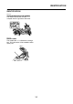
PERIODIC MAINTENANCE EAS21030 EAS20680 CHECKING THE FUEL LINE The following procedure applies to all of the fuel and breather hoses. 1. Remove: • Center cover Refer to “GENERAL CHASSIS” on page 4-1. • Side covers Refer to “GENERAL CHASSIS” on page 4-1. • Footboards Refer to “GENERAL CHASSIS” on page 4-1. • Storage box Refer to “GENERAL CHASSIS” on page 4-1. 2. Check: • Fuel hose “1” • Fuel tank breather hose “2” Cracks/damage → Replace. Loose connection → Connect properly.
PERIODIC MAINTENANCE 7. Remove: • Timing mark accessing plug “1” • Crankshaft end access cover “2” 8. Install: • Spark plug Spark plug 13 Nm (1.3 m·kgf, 9.4 ft·lbf) TIP Before installing the spark plug, clean the spark plug and gasket surface. 9. Connect: • Spark plug cap 10. Install: • Radiator cover Refer to “GENERAL CHASSIS” on page 4-1. EAS20490 ADJUSTING THE VALVE CLEARANCE The following procedure applies to all of the valves.
PERIODIC MAINTENANCE TIP #2 • TDC on the compression stroke can be found when the cylinder #1 camshaft lobes are turned away from each other. • In order to be sure that the piston is at TDC, the alignment mark “c” on the intake camshaft sprocket and the alignment mark “d” on the exhaust camshaft sprocket must align with the cylinder head mating surface as shown in the illustration. #1 A A. Front d.
PERIODIC MAINTENANCE TIP • Cover the timing chain opening with a rag to prevent the valve pad from falling into the crankcase. • Make a note of the position of each valve lifter “1” and valve pad “2” so that they can be installed in the correct place. d. Calculate the sum of the values obtained in steps (b) and (c) to determine the required valve pad thickness and the valve pad number. Example: 1.55 mm (0.061 in) + 0.03 mm (0.001 in) = 1.58 mm (0.062 in) The valve pad number is 158. e.
PERIODIC MAINTENANCE • The valve lifter must turn smoothly when rotated by hand. • Install the valve lifter and the valve pad in the correct place. be clean, and the engine should have adequate compression. 1. Start the engine and let it warm up for several minutes. 2. Remove: • Radiator cover Refer to “GENERAL CHASSIS” on page 4-1. • Side cover (right) Refer to “GENERAL CHASSIS” on page 4-1. 3. Install: • Digital tachometer (onto the spark plug lead of cylinder #1) 2 1 g.
PERIODIC MAINTENANCE 6. Install: • Side cover (right) Refer to “GENERAL CHASSIS” on page 4-1. • Radiator cover Refer to “GENERAL CHASSIS” on page 4-1. EAS20571 SYNCHRONIZING THE THROTTLE BODY TIP Prior to synchronizing the throttle body, the valve clearance and the engine idling speed should be properly adjusted and the ignition timing should be checked. 4. Install: • Hose “1” (Parts No.: 5JW-24311-00) • 3-Way joint “2” (Parts No.
PERIODIC MAINTENANCE 5. Start the engine and let it warm up for several minutes. 6. Check: • Engine idling speed Out of specification → Adjust. Refer to “ADJUSTING THE ENGINE IDLING SPEED” on page 3-8. 8. Measure: • Engine idling speed Out of specification → Adjust. Make sure that the vacuum pressure is within specification. 9. Stop the engine and remove the measuring equipment. 10. Adjust: • Throttle grip free play Refer to “CHECKING THE THROTTLE GRIP” on page 3-32. Engine idling speed 1100–1300 r/min 7.
PERIODIC MAINTENANCE 3. Press the left set button to select the CO adjustment mode “Co” or the diagnostic monitoring mode “dIAG”. • Footboard (right) Refer to “GENERAL CHASSIS” on page 4-1. 2. Check: • Cylinder head breather hose “1” Cracks/damage → Replace. Loose connection → Connect properly. ECA14920 Make sure the cylinder head breather hose is routed correctly. 4. After selecting “Co”, simultaneously press the left set and right set buttons for 2 seconds or more to execute the selection. 5.
PERIODIC MAINTENANCE 3. Check: • Air filter element “1” Damage → Replace. 2. Check: • Exhaust assembly “1” Cracks/damage → Replace. • Gasket “2” Exhaust gas leaks → Replace. 3. Check: Tightening torque • Exhaust assembly nut (front) “3” • Exhaust assembly nut (rear) “4” • O2 sensor “5” TIP • Replace the air filter element every 20000 km (12000 mi) of operation. • The air filter needs more frequent service if you are riding in unusually wet or dusty areas. Exhaust assembly nut (front) 20 Nm (2.
PERIODIC MAINTENANCE 2. Remove: • V-belt case air filter element (left) “1” 5. Check: • V-belt case air filter elements Damage → Replace. 3. Remove: • V-belt case air filter case cover “1” • V-belt case air filter case “2” • V-belt case air filter element (right) “3” ECA13440 Since the V-belt case air filter element is a dry type, do not let grease or water contact it. 6.
PERIODIC MAINTENANCE reaction, leading to poor brake performance. • When refilling, be careful that water does not enter the brake master cylinder reservoir. Water will significantly lower the boiling point of the brake fluid and could cause vapor lock. TIP Drive on the road, operate the front and rear brakes separately and check to see if the brakes are operating properly. EAS21240 CHECKING THE BRAKE FLUID LEVEL 1. Stand the vehicle on a level surface.
PERIODIC MAINTENANCE • A soft or spongy feeling in the brake lever can indicate the presence of air in the brake system. Before the vehicle is operated, the air must be removed by bleeding the brake system. Air in the brake system will considerably reduce in loss of control and possibly an accident. Therefore, check and if necessary, bleed the brake system. ECA13490 EWA13060 WARNING After adjusting the brake lever position, make sure there is no brake drag.
PERIODIC MAINTENANCE EAS30770 BLEEDING THE HYDRAULIC BRAKE SYSTEM (ABS) EWA14000 WARNING Always bleed the brake system when the brake related parts are removed. ECA17050 • Bleed the brake system in the following order. • 1st step: Front brake calipers • 2rd step: Rear brake caliper EWA15740 WARNING Bleed the ABS whenever: • the system is disassembled. • a brake hose is loosened, disconnected or replaced. • the brake fluid level is very low. • brake operation is faulty. A. Front brake caliper B.
PERIODIC MAINTENANCE l. Tighten the bleed screw to specification. Front brake caliper bleed screw 5 Nm (0.5 m·kgf, 3.6 ft·lbf) Rear brake caliper bleed screw 6 Nm (0.6 m·kgf, 4.3 ft·lbf) m. Fill the brake master cylinder reservoir to the proper level with the specified brake fluid. Refer to “CHECKING THE BRAKE FLUID LEVEL” on page 3-14. 2. Check: • Brake hose holders Loose connection → Tighten the holder bolt. 3. Hold the vehicle upright and apply the rear brake several times. 4.
PERIODIC MAINTENANCE Direction “b” Rear brake lock cable length increased. Direction “c” Rear brake lock cable length decreased. g. Install the cap of the rear brake lock adjusting nut. ▲▲▲▲▲▲▲▲▲▲▲▲▲▲▲▲▲▲▲▲▲▲▲▲▲▲▲▲▲▲ EAS59C1305 CHECKING THE REAR BRAKE LOCK 1. Check: • Rear brake lock operation Apply the rear brake lock, and then pushing the vehicle for properly locks the rear brake lock. Rear brake lock not working properly → Check the rear brake lock cable and rear brake lock pads.
PERIODIC MAINTENANCE 4. Check: • Rear brake lock caliper boots Cracks/damage → Replace. Refer to “REAR BRAKE” on page 4-50. EAS59C1301 CHECKING THE REAR BRAKE LOCK PADS The following procedure applies to all of the brake pads. 1. Operate the rear brake lock. 2. Check: • Rear brake lock pad Wear indicators “1” almost touch the brake disc → Replace the brake pads as a set. Refer to “REPLACING THE REAR BRAKE LOCK PADS” on page 4-64.
PERIODIC MAINTENANCE 2. Check: • Tire surfaces Damage/wear → Replace the tire. EWA13210 WARNING New tires have a relatively low grip on the road surface until they have been slightly worn. Therefore, approximately 100 km should be traveled at normal speed before any high-speed riding is done. TIP For tires with a direction of rotation mark “1”: • Install the tire with the mark pointing in the direction of wheel rotation. • Align the mark “2” with the valve installation point. 1. Tire tread depth 2.
PERIODIC MAINTENANCE 2. Check: • Drive belt External tooth cracks “A” → Replace. Missing teeth “B” → Replace. Hook wear “C” → Replace. Stone damage “D” → Replace if damage is on the edge. Internal tooth cracks (hairline) “E” → OK to run, but monitor condition. Chipping (not serious) “F” → OK to run, but monitor condition. Fuzzy edge cord “G” → OK to run, but monitor condition Bevel wear (outboard edge only) “H” → OK to run, but monitor condition. Refer to “BELT DRIVE” on page 4-92.
PERIODIC MAINTENANCE TIP TIP Measure the drive belt slack after setting the tension gauge at 13.4 position on the scale. • Push the rear wheel forward to make sure that there is no clearance between the adjusting block and the ends of the swingarm. • After adjusting the drive belt slack to 13.4, measure the distance “c” on the left side and then adjust the distance on the right side to the same value as measured on the left side.
PERIODIC MAINTENANCE 5. Lubricate: • Drive axle “1” Recommended lubricant YAMAHA GREASE “H” or Polyurea Grease® 6. Lubricate: • Drive pulley assembly inner part “2” Recommended lubricant YAMAHA GREASE “H” or Polyurea Grease® 7. Install: • All removed parts 8. Adjust: • Drive belt slack Refer to “ADJUSTING THE DRIVE BELT SLACK” on page 3-21. EAS21500 CHECKING AND ADJUSTING THE STEERING HEAD 1. Stand the vehicle on a level surface.
PERIODIC MAINTENANCE in both directions. If any binding is felt, remove the lower bracket and check the upper and lower bearings. Refer to “STEERING HEAD” on page 4-89. e. Install the rubber washer “3”. f. Install the upper ring nut “2”. g. Finger tighten the upper ring nut “2”, then align the slots of both ring nuts. If necessary, hold the lower ring nut and tighten the upper ring nut until their slots are aligned. h. Install the lock washer “1”. ▼▼▼▼▼▼▼▼▼▼▼▼▼▼▼▼▼▼▼▼▼▼▼▼▼▼▼▼▼▼ a.
PERIODIC MAINTENANCE EAS21720 LUBRICATING THE SIDESTAND Lubricate the pivoting point, metal-to-metal moving parts and spring contact point of the sidestand. Recommended lubricant Lithium-soap-based grease EAS30860 CHECKING THE CENTERSTAND 1. Check: • Centerstand operation Check that the centerstand moves smoothly. Rough movement → Repair or replace. EAS59C1306 CHECKING THE REAR SHOCK ABSORBER ASSEMBLY 1.
PERIODIC MAINTENANCE EAS20791 CHANGING THE ENGINE OIL 1. Start the engine, warm it up for several minutes, and then turn it off. 2. Place a container under the engine oil drain bolt. 3.
PERIODIC MAINTENANCE Engine oil quantity Total amount 3.50 L (3.70 US qt, 3.08 Imp.qt) Without oil filter cartridge replacement 2.70 L (2.85 US qt, 2.38 Imp.qt) With oil filter cartridge replacement 2.90 L (3.07 US qt, 2.55 Imp.qt) 8. Install: • Engine oil filler cap b. Lubricate the O-ring “3” of the new oil filter cartridge with a thin coat of lithium-soapbased grease. (along with the O-ring New ) 9. Start the engine, warm it up for several minutes, and then turn it off. 10.
PERIODIC MAINTENANCE f. Tighten the oil check bolt to specification. Oil pressure gauge set 90890-03120 or Oil pressure adapter B 90890-03124 Pressure gauge 90890-03153 YU-03153 Engine oil check bolt 20 Nm (2.0 m·kgf, 14 ft·lbf) g. Install the bottom side cowling and bottom center cowling. Refer to “GENERAL CHASSIS” on page 41. ▲▲▲▲▲▲▲▲▲▲▲▲▲▲▲▲▲▲▲▲▲▲▲▲▲▲▲▲▲▲ EAS20820 MEASURING THE ENGINE OIL PRESSURE 1.
PERIODIC MAINTENANCE 3. Start the engine, warm it up for several minutes, and then turn it off. 4. Check: • Coolant level Engine oil pressure check point plug 12 Nm (1.2 m·kgf, 8.7 ft·lbf) EAS21110 TIP CHECKING THE COOLANT LEVEL 1. Stand the vehicle on a level surface. Before checking the coolant level, wait a few minutes until it settles. TIP • Place the vehicle on the centerstand. • Make sure the vehicle is upright. EAS21120 CHECKING THE COOLING SYSTEM 1.
PERIODIC MAINTENANCE press down on the radiator cap and turn it counterclockwise to remove. 3. Install: • Footboards Refer to “GENERAL CHASSIS” on page 4-1. • Side covers Refer to “GENERAL CHASSIS” on page 4-1. • Center cover Refer to “GENERAL CHASSIS” on page 4-1. TIP When removing the radiator cap, hold the radiator filler pipe “2”. EAS21131 CHANGING THE COOLANT 1. Remove: • Center cover Refer to “GENERAL CHASSIS” on page 4-1. • Side cover (left) Refer to “GENERAL CHASSIS” on page 4-1.
PERIODIC MAINTENANCE Recommended antifreeze High-quality ethylene glycol antifreeze containing corrosion inhibitors for aluminum engines Mixing ratio 1:1 (antifreeze:water) Radiator capacity (including all routes) 1.50 L (1.59 US qt, 1.32 Imp.qt) Coolant reservoir capacity (up to the maximum level mark) 0.27 L (0.29 US qt, 0.24 Imp.qt) 12. Install: • Coolant reservoir cap 13. Start the engine, warm it up for several minutes, and then stop it. 14.
PERIODIC MAINTENANCE 2. Check: • V-belt Cranks/damage/wear → Replace. Grease/oil → Clean the primary and secondary pulleys. Refer to “V-BELT AUTOMATIC TRANSMISSION” on page 5-39. Recommended lubricant Engine oil or a suitable cable lubricant TIP Hold the cable end upright and pour a few drops of lubricant into the cable sheath or use a suitable lubricating device. TIP Replace the V-belt every 20000 km (12500 mi) of operation.
PERIODIC MAINTENANCE EAS21760 CHECKING AND CHARGING THE BATTERY Refer to “CHECKING AND CHARGING THE BATTERY” on page 8-127. EAS21770 CHECKING THE FUSES Refer to “CHECKING THE FUSES” on page 8127. EAS21790 REPLACING THE HEADLIGHT BULBS The following procedure applies to both of the headlight bulbs. 1. Remove: • Front cover Refer to “GENERAL CHASSIS” on page 4-1. 2. Disconnect: • Headlight coupler “1” 4.
PERIODIC MAINTENANCE ECA13690 TIP Other than the socket wrench, the adjusting screws can be turned with a screwdriver (Phillips No. 2) “2” as shown in the illustration. Avoid touching the glass part of the headlight bulb to keep it free from oil, otherwise the transparency of the glass, the life of the bulb and the luminous flux will be adversely affected. If the headlight bulb gets soiled, thoroughly clean it with a cloth moistened with alcohol or lacquer thinner.
PERIODIC MAINTENANCE 3-35
CHASSIS GENERAL CHASSIS....................................................................................4-1 REMOVING THE WINDSHIELD.............................................................4-9 INSTALLING THE WINDSHIELD............................................................4-9 ADJUSTING THE WINDSHIELD HEIGHT ...........................................4-10 REMOVING THE FRONT COVER .......................................................4-10 INSTALLING THE FRONT COVER ................................
FRONT BRAKE ..........................................................................................4-37 INTRODUCTION ..................................................................................4-42 CHECKING THE FRONT BRAKE DISCS ............................................4-42 REPLACING THE FRONT BRAKE PADS ............................................4-43 REMOVING THE FRONT BRAKE CALIPERS .....................................4-44 DISASSEMBLING THE FRONT BRAKE CALIPERS ...........................
FRONT FORK.............................................................................................4-81 REMOVING THE FRONT FORK LEGS ...............................................4-83 DISASSEMBLING THE FRONT FORK LEGS .....................................4-83 CHECKING THE FRONT FORK LEGS................................................4-84 ASSEMBLING THE FRONT FORK LEGS ...........................................4-85 INSTALLING THE FRONT FORK LEGS ..............................................
GENERAL CHASSIS EAS21830 GENERAL CHASSIS Removing the windshield and front cowling assembly Order 1 2 3 4 5 6 7 8 Job/Parts to remove Front left storage box Radiator cover Side panel Windshield cover Windshield bracket Windshield Front cover Rear view mirror Windshield inner panel Headlight sub-wire harness coupler Front cowling assembly Q’ty 2 2 1 1 2 1 1 1 Remarks Refer to “GENERAL CHASSIS” on page 4-1. Refer to “GENERAL CHASSIS” on page 4-1. Refer to “GENERAL CHASSIS” on page 4-1. Disconnect.
GENERAL CHASSIS Disassembling the front cowling assembly Order 1 2 3 4 5 6 7 8 Job/Parts to remove Side cowling Headlight under panel Turn signal light coupler Auxiliary light coupler Left turn signal light Right turn signal light Headlight sub-wire harness Headlight bulb Q’ty 2 1 2 1 1 1 1 2 Remarks Disconnect. Disconnect. For assembly, reverse the disassembly procedure.
GENERAL CHASSIS Removing the storage compartment Order 1 2 3 4 5 6 7 8 9 Job/Parts to remove Front cowling assembly Inner panel center cover Front left storage box Battery Meter coupler Meter panel assembly Meter assembly Meter cover Front right storage box Storage compartment Q’ty 1 1 1 1 1 1 1 1 1 Remarks Refer to “GENERAL CHASSIS” on page 4-1. Disconnect. For installation, reverse the removal procedure.
GENERAL CHASSIS Removing the bottom cowling Order 1 2 3 4 5 6 7 8 9 Job/Parts to remove Footboard mat Radiator cover Side panel Center cover Side cover Bottom side cowling Bottom center cowling Side cover moulding Footboard Q’ty 4 1 2 1 2 2 1 2 2 Remarks For installation, reverse the removal procedure.
GENERAL CHASSIS Removing the rear cowling assembly Order 1 2 3 4 5 6 7 8 9 10 11 12 13 Job/Parts to remove Side panel Footboard O2 sensor lead Q’ty Seat Fuel tank cover Grab bar Rear cover Taillight lead cover Taillight lead guide Storage box light switch coupler Storage box light switch Seat hinge assembly Taillight assembly coupler License plate light lead coupler Rear turn signal light lead coupler Mud guard 1 1 2 1 1 1 1 1 1 1 1 2 1 Remarks Refer to “GENERAL CHASSIS” on page 4-1.
GENERAL CHASSIS Removing the rear cowling assembly Order 14 15 Job/Parts to remove Q’ty 1 1 Rear fender Rear cowling assembly Remarks For installation, reverse the removal procedure.
GENERAL CHASSIS Disassembling the rear cowling assembly Order 1 2 3 4 5 6 7 Job/Parts to remove Taillight bracket Left rear cowling Right rear cowling Left turn signal light Right turn signal light Taillight Q’ty 1 1 1 1 1 1 Taillight cover Remarks 1 For assembly, reverse the disassembly procedure.
GENERAL CHASSIS Removing the storage box Order 1 2 3 4 5 6 7 8 9 10 11 Job/Parts to remove Fuel pump coupler access cover Fuel pump coupler Fuel hose connector cover Fuel hose Fuel tank overflow hose Storage box inner mat Seat lock Storage box light connector Rollover valve stay Storage box Storage box light Q’ty 1 1 1 1 1 1 1 2 1 1 1 Remarks Disconnect. Disconnect. Disconnect. For installation, reverse the removal procedure.
GENERAL CHASSIS EAS59C1407 ▼▼▼▼▼▼▼▼▼▼▼▼▼▼▼▼▼▼▼▼▼▼▼▼▼▼▼▼▼▼ REMOVING THE WINDSHIELD 1. Remove: • Windshield cover a. Assembling the windshield “1” and windshield brackets “2” with the windshield screws “3”. b. Installing the windshield assembly with the windshield bracket bolts “4”. Windshield screw 0.5 Nm (0.05 m·kgf, 0.36 ft·lbf) Windshield bracket bolt 10 Nm (1.0 m·kgf, 7.2 ft·lbf) ▼▼▼▼▼▼▼▼▼▼▼▼▼▼▼▼▼▼▼▼▼▼▼▼▼▼▼▼▼▼ a. Remove the quick fastener “1”. ▲▲▲▲▲▲▲▲▲▲▲▲▲▲▲▲▲▲▲▲▲▲▲▲▲▲▲▲▲▲ 2.
GENERAL CHASSIS EAS59C1427 EAS59C1409 ADJUSTING THE WINDSHIELD HEIGHT 1. Adjust: • Windshield height REMOVING THE FRONT COVER 1. Remove: • Front cover ▼▼▼▼▼▼▼▼▼▼▼▼▼▼▼▼▼▼▼▼▼▼▼▼▼▼▼▼▼▼ a. Remove the windshield cover and windshield assembly. Refer to “REMOVING THE WINDSHIELD” on page 4-9. b. Remove the rubber caps “1”. ▼▼▼▼▼▼▼▼▼▼▼▼▼▼▼▼▼▼▼▼▼▼▼▼▼▼▼▼▼▼ a. Remove the two metal clips “1” and six claws “2” from the front cover. c. Install the rubber caps “1” in the desired position. b.
GENERAL CHASSIS d. Fit the two metal clips “4” and six claws “5” of the front cover. ▲▲▲▲▲▲▲▲▲▲▲▲▲▲▲▲▲▲▲▲▲▲▲▲▲▲▲▲▲▲ EAS59C1410 INSTALLING THE FRONT COVER 1. Install: • Front cover ▲▲▲▲▲▲▲▲▲▲▲▲▲▲▲▲▲▲▲▲▲▲▲▲▲▲▲▲▲▲ EAS59C1411 REMOVING THE WINDSHIELD INNER PANEL 1. Remove: • Windshield inner panel ▼▼▼▼▼▼▼▼▼▼▼▼▼▼▼▼▼▼▼▼▼▼▼▼▼▼▼▼▼▼ a. Insert the three projections “1” of the front cover. ▼▼▼▼▼▼▼▼▼▼▼▼▼▼▼▼▼▼▼▼▼▼▼▼▼▼▼▼▼▼ b. Fit the two claws “2” of the end of the front cover. c.
GENERAL CHASSIS ▼▼▼▼▼▼▼▼▼▼▼▼▼▼▼▼▼▼▼▼▼▼▼▼▼▼▼▼▼▼ ▲▲▲▲▲▲▲▲▲▲▲▲▲▲▲▲▲▲▲▲▲▲▲▲▲▲▲▲▲▲ a. Removing the quick fasteners “1”. b. Removing the screws “2”. c. Remove the metal clip “3”. EAS59C1412 INSTALLING THE WINDSHIELD INNER PANEL 1. Install: • Windshield inner panel ▲▲▲▲▲▲▲▲▲▲▲▲▲▲▲▲▲▲▲▲▲▲▲▲▲▲▲▲▲▲ EAS59C1414 INSTALLING THE SIDE PANEL 1. Install: • Side panel ▼▼▼▼▼▼▼▼▼▼▼▼▼▼▼▼▼▼▼▼▼▼▼▼▼▼▼▼▼▼ a. Insert the two projections “1” of the windshield inner panel. b. Installing the bolts “2”. c.
GENERAL CHASSIS ▼▼▼▼▼▼▼▼▼▼▼▼▼▼▼▼▼▼▼▼▼▼▼▼▼▼▼▼▼▼ a. Insert the four claws “1”. b. Installing the screws “2”. ▲▲▲▲▲▲▲▲▲▲▲▲▲▲▲▲▲▲▲▲▲▲▲▲▲▲▲▲▲▲ EAS59C1415 REMOVING THE CENTER COVER 1. Remove: • Center cover ▲▲▲▲▲▲▲▲▲▲▲▲▲▲▲▲▲▲▲▲▲▲▲▲▲▲▲▲▲▲ EAS59C1417 REMOVING THE SIDE COVER 1. Remove: • Side cover ▼▼▼▼▼▼▼▼▼▼▼▼▼▼▼▼▼▼▼▼▼▼▼▼▼▼▼▼▼▼ a. Removing the screws “1”. b. Use an appropriate hook from the service hole “2” to raise the center cover. c.
GENERAL CHASSIS ▲▲▲▲▲▲▲▲▲▲▲▲▲▲▲▲▲▲▲▲▲▲▲▲▲▲▲▲▲▲ EAS59C1420 ▼▼▼▼▼▼▼▼▼▼▼▼▼▼▼▼▼▼▼▼▼▼▼▼▼▼▼▼▼▼ INSTALLING THE SIDE COVER MOULDING 1. Install: • Side cover moulding a. Insert the five projections “1”. b. Insert the five claws “2”. c. Installing the bolts “3”. ▼▼▼▼▼▼▼▼▼▼▼▼▼▼▼▼▼▼▼▼▼▼▼▼▼▼▼▼▼▼ a. Insert the five claws “1”. b. Installing the screws “2”. c. Installing the quick fastener “3”. ▲▲▲▲▲▲▲▲▲▲▲▲▲▲▲▲▲▲▲▲▲▲▲▲▲▲▲▲▲▲ EAS59C1419 REMOVING THE SIDE COVER MOULDING 1.
GENERAL CHASSIS b. Fit the three claws “1”. c. Installing the bolts “2”. d. Installing the screws “3”. A. Left side B. Right side c. Remove the three claws “3”. d. Slide the footboard upwards, pull it toward you, and then remove it. A. Left side B. Right side ▲▲▲▲▲▲▲▲▲▲▲▲▲▲▲▲▲▲▲▲▲▲▲▲▲▲▲▲▲▲ ▲▲▲▲▲▲▲▲▲▲▲▲▲▲▲▲▲▲▲▲▲▲▲▲▲▲▲▲▲▲ EAS59C1422 EAS59C1423 INSTALLING THE FOOTBOARD 1. Install: • Footboard REMOVING THE REAR COVER 1.
GENERAL CHASSIS b. Holding the rear side of the rear cover and slightly applying a force upward, slide the cover rearward to remove it. ▼▼▼▼▼▼▼▼▼▼▼▼▼▼▼▼▼▼▼▼▼▼▼▼▼▼▼▼▼▼ a. Removing the screws “1”. b. There are six claws “2”. Remove them, starting from the top. ▲▲▲▲▲▲▲▲▲▲▲▲▲▲▲▲▲▲▲▲▲▲▲▲▲▲▲▲▲▲ EAS59C1424 INSTALLING THE REAR COVER 1. Install: • Rear cowling ▲▲▲▲▲▲▲▲▲▲▲▲▲▲▲▲▲▲▲▲▲▲▲▲▲▲▲▲▲▲ EAS59C1426 INSTALLING THE INNER PANEL CENTER COVER 1.
GENERAL CHASSIS 2. Install: • Fuel hose connector cover EAS59C1428 REMOVING THE FUEL HOSE 1. Remove: • Fuel hose connector cover “1” 2. Disconnect: • Fuel hose “2” ECA59C1702 When installing the fuel hose, make sure that it is securely connected, and that the fuel hose connector cover is in the correct position, otherwise the fuel hose will not be properly installed. EWA15910 WARNING Cover fuel hose connections with a cloth when disconnecting them.
FRONT WHEEL EAS21870 FRONT WHEEL Removing the front wheel and brake discs Order 1 2 3 4 5 6 7 8 9 10 11 12 13 Job/Parts to remove Front cowling assembly Front wheel sensor coupler Front brake hose holder Cable guide Front wheel sensor Front brake caliper Front wheel axle pinch bolt Front wheel axle Front wheel Front wheel sensor housing Collar Collar Front brake disc Front fender Q’ty 1 2 1 1 2 1 1 1 1 1 1 2 1 Remarks Refer to “GENERAL CHASSIS” on page 4-1. Disconnect. Loosen. Length: 12 mm (0.
FRONT WHEEL Disassembling the front wheel Order 1 2 3 4 5 6 Job/Parts to remove Front wheel sensor rotor Oil seal Wheel bearing (right) Collar Wheel bearing (left) Air valve Q’ty 1 2 1 1 1 1 Remarks For assembly, reverse the disassembly procedure.
FRONT WHEEL • Do not drop the wheel sensor rotor or subject it to shocks. • If any solvent gets on the wheel sensor rotor, wipe it off immediately. EAS21900 REMOVING THE FRONT WHEEL ECA59C2405 Keep magnets (including magnetic pick-up tools, magnetic screwdrivers, etc.) away from the front wheel hub “1”, otherwise the wheel sensor rotor equipped in the wheel hub may be damaged, resulting in improper performance of the ABS system. 1.
FRONT WHEEL EWA13460 WARNING Do not attempt to straighten a bent wheel axle. EAS22010 MAINTENANCE OF THE FRONT WHEEL SENSOR AND SENSOR ROTOR ECA59C2407 • Handle the ABS components with care since they have been accurately adjusted. Keep them away from dirt and do not subject them to shocks. • The front wheel sensor cannot be disassembled. Do not attempt to disassemble it. If faulty, replace with a new one. • Keep magnets (including magnetic pickup tools, magnetic screwdrivers, etc.
FRONT WHEEL c. If the deflection is above specification, remove the sensor rotor from the wheel, rotate it by one bolt hole, and then install it. Wheel sensor rotor bolt 8 Nm (0.8 m·kgf, 5.8 ft·lbf) LOCTITE® ECA59C2408 Replace the wheel sensor rotor bolts with new ones. 3. Measure: • Front wheel sensor rotor deflection Out of specification → Clean the installation surface of the wheel sensor rotor and correct the wheel sensor rotor deflection, or replace the wheel sensor rotor. d.
FRONT WHEEL d. Install the new oil seals ▲▲▲▲▲▲▲▲▲▲▲▲▲▲▲▲▲▲▲▲▲▲▲▲▲▲▲▲▲▲ a. 45°–55° 2. Install: • Air valve A. Wheel rotation direction B. Left side TIP • Fasten air valve nut “1” and tighten air valve locknut “2” to 3.0 Nm (0.30 m·kgf, 2.2 ft·lbf). • When installing the air valve, orient the air valve referring to the illustration. ▲▲▲▲▲▲▲▲▲▲▲▲▲▲▲▲▲▲▲▲▲▲▲▲▲▲▲▲▲▲ EAS21970 ADJUSTING THE FRONT WHEEL STATIC BALANCE ▼▼▼▼▼▼▼▼▼▼▼▼▼▼▼▼▼▼▼▼▼▼▼▼▼▼▼▼▼▼ TIP a. Tighten the air valve nut “1”.
FRONT WHEEL e. When the wheel stops, put an “X2” mark at the bottom of the wheel. d. Repeat steps (b) and (c) until the front wheel is balanced. ▲▲▲▲▲▲▲▲▲▲▲▲▲▲▲▲▲▲▲▲▲▲▲▲▲▲▲▲▲▲ 4. Check: • Front wheel static balance ▼▼▼▼▼▼▼▼▼▼▼▼▼▼▼▼▼▼▼▼▼▼▼▼▼▼▼▼▼▼ a. Turn the front wheel and make sure it stays at each position shown. f. Repeat steps (c) through (e) several times until all the marks come to rest at the same spot. g. The spot where all the marks come to rest is the front wheel’s heavy spot “X”.
FRONT WHEEL 2. Check: • Front brake discs Refer to “CHECKING THE FRONT BRAKE DISCS” on page 4-42. 3. Lubricate: • Oil seal lips • Distance “a” (between the wheel sensor rotor “1” and wheel sensor housing “2”) Out of specification → Reinstall the bearing or replace the wheel sensor rotor. Distance “a” (between the wheel sensor rotor and wheel sensor housing) 28.7–29.3 mm (1.13–1.15 in) Recommended lubricant Lithium-soap-based grease 4.
FRONT WHEEL 8. Check: • Front wheel sensor installation Check if the wheel sensor housing is installed properly.
REAR WHEEL EAS22020 REAR WHEEL Removing the rear wheel Order 1 2 3 4 5 6 7 8 9 10 11 12 13 14 Job/Parts to remove Side cover (right) Rear wheel sensor coupler Rear brake hose holder (right) Rear wheel sensor lead holder Rear wheel sensor Rear brake caliper Rear brake pad Rear brake lock cable adjusting nut Pin Rear brake lock spring Rear brake lock caliper Drive belt upper guard Drive belt lower guard Drive belt adjusting locknut Drive belt adjusting bolt Q’ty 1 1 1 1 1 2 1 1 1 1 1 1 2 2 Remarks Refer
REAR WHEEL Removing the rear wheel Order 15 16 17 18 19 20 21 22 23 24 25 26 Job/Parts to remove Wheel axle nut Washer Adjusting block (right) Rear wheel axle Adjusting block (left) Rear wheel Rear brake caliper bracket Caliper bolt boot Rear wheel sensor housing Collar (right) Collar (left) Dust cover Q’ty 1 1 1 1 1 1 1 2 1 1 1 1 Remarks For installation, reverse the removal procedure. * When replacing the rear brake caliper or rear brake caliper bracket, replace them as a set.
REAR WHEEL Removing the rear brake disc and rear wheel pulley Order 1 2 3 4 5 Job/Parts to remove Rear brake disc Rear wheel sensor rotor Drive belt guide Rear wheel pulley Rear wheel Q’ty 1 1 1 1 1 Remarks For installation, reverse the removal procedure.
REAR WHEEL Disassembling the rear wheel assembly Order 1 2 3 4 Job/Parts to remove Q’ty 2 1 1 1 Oil seal Wheel bearing (left) Collar Wheel bearing (right) Remarks For assembly, reverse the disassembly procedure.
REAR WHEEL EAS22040 REMOVING THE REAR WHEEL (DISC) ECA59C2410 Keep magnets (including magnetic pick-up tools, magnetic screwdrivers, etc.) away from the rear wheel hub “1”, otherwise the wheel sensor rotor equipped in the wheel hub may be damaged, resulting in improper performance of the ABS system. 4.
REAR WHEEL EAS22091 ▼▼▼▼▼▼▼▼▼▼▼▼▼▼▼▼▼▼▼▼▼▼▼▼▼▼▼▼▼▼ CHECKING THE REAR WHEEL 1. Check: • Wheel axle • Wheel bearings • Oil seals Refer to “CHECKING THE FRONT WHEEL” on page 4-20. 2. Check: • Tire • Rear wheel Damage/wear → Replace. Refer to “CHECKING THE TIRES” on page 3-19 and “CHECKING THE WHEELS” on page 3-19. 3. Measure: • Radial wheel runout • Lateral wheel runout Refer to “CHECKING THE FRONT WHEEL” on page 4-20. a. Remove the drive belt guide bolts and the drive belt guide. b.
REAR WHEEL EAS22200 MAINTENANCE OF THE REAR WHEEL SENSOR AND SENSOR ROTOR ECA59C2411 • Handle the ABS components with care since they have been accurately adjusted. Keep them away from dirt and do not subject them to shocks. • The rear wheel sensor cannot be disassembled. Do not attempt to disassemble it. If faulty, replace with a new one. • Keep magnets (including magnetic pickup tools, magnetic screwdrivers, etc.) away from the wheel sensor rotor.
REAR WHEEL EAS22160 TIP INSTALLING THE REAR WHEEL (DISC) 1. Install: • Rear brake disc Use a socket “4” that matches the diameter of the wheel bearing outer race. Rear brake disc bolt 30Nm (3.0 m·kgf, 22 ft·lbf) LOCTITE® ECA59C1401 Replace the brake disc bolts with new ones. TIP Tighten the brake disc bolts in stages and in a crisscross pattern. b. Install the collar. c. Install the new wheel bearing (left side).
REAR WHEEL • When installing the rear brake caliper bracket and the rear wheel sensor housing, align the projection “c” on the rear brake caliper bracket with the slot “d” of the rear wheel sensor housing. • After installing the rear wheel to the vehicle, make sure that the projection “e” on the brake caliper bracket and the projection “f” on the rear wheel sensor housing are aligned. • Install the left adjusting block so that projection “g” faces to the front of the vehicle.
REAR WHEEL 10. Check: • Rear wheel sensor installation Check if the wheel sensor housing is installed properly. 8. Measure: TIP Measure the distance “a” only if the wheel bearings, wheel sensor rotor, or both were replaced. • Distance “a” (between the wheel sensor rotor “1” and wheel sensor housing “2”) Out of specification → Reinstall the bearing or replace the wheel sensor rotor. Distance “a” (between the wheel sensor rotor and wheel sensor housing) 29.2–29.7 mm (1.15–1.17 in) 9.
FRONT BRAKE EAS22210 FRONT BRAKE Removing the front brake pads Order 1 2 3 4 5 6 7 8 9 Job/Parts to remove Q’ty Front brake hose holder bolt Front brake caliper bolt Front brake caliper Brake pad clip Brake pad pin Brake pad spring Front brake pad Bleed screw Bleed screw 1 2 1 2 1 1 2 1 1 4-37 Remarks The following procedure applies to both of the front brake calipers. Left brake caliper side Right brake caliper side For installation, reverse the removal procedure.
FRONT BRAKE Removing the front brake master cylinder Order Job/Parts to remove Upper handlebar cover Q’ty Brake fluid 1 2 3 4 5 6 7 8 9 10 11 Brake master cylinder reservoir cap Brake master cylinder reservoir diaphragm holder Brake master cylinder reservoir diaphragm Front brake lever Front brake light switch connector Brake hose union bolt Front brake hose Brake hose gasket Front brake master cylinder holder Front brake master cylinder Front brake light switch Remarks Refer to “HANDLEBAR” on page 4-
FRONT BRAKE Disassembling the front brake master cylinder Order 1 2 Job/Parts to remove Brake master cylinder kit Brake master cylinder body Q’ty 1 1 Remarks For assembly, reverse the disassembly procedure.
FRONT BRAKE Removing the front brake calipers Order Job/Parts to remove Q’ty Brake fluid 1 2 3 4 5 6 Front brake hose holder bolt Brake hose union bolt Brake hose gasket Front brake hose Front brake caliper bolt Front brake caliper Remarks The following procedure applies to both of the front brake calipers. Drain. Refer to “BLEEDING THE HYDRAULIC BRAKE SYSTEM (ABS)” on page 3-16. 1 1 2 1 2 1 For installation, reverse the removal procedure.
FRONT BRAKE Disassembling the front brake calipers Order 1 2 3 4 5 6 7 8 9 Job/Parts to remove Q’ty Brake pad clip Brake pad pin Brake pad spring Front brake pad Brake caliper piston Brake caliper piston dust seal Brake caliper piston seal Bleed screw Bleed screw 2 1 1 2 4 4 4 1 1 4-41 Remarks The following procedure applies to both of the front brake calipers. Left brake caliper side Right brake caliper side For assembly, reverse the disassembly procedure.
FRONT BRAKE c. Remove the brake caliper. d. Hold the dial gauge at a right angle against the brake disc surface. e. Measure the deflection 1.5 mm (0.06 in) below the edge of the brake disc. EAS22221 INTRODUCTION EWA14101 WARNING Disc brake components rarely require disassembly. Therefore, always follow these preventive measures: • Never disassemble brake components unless absolutely necessary.
FRONT BRAKE 2. Remove: • Brake pads “1” TIP Tighten the brake disc bolts in stages and in a crisscross pattern. 3. Measure: • Brake pad wear limit “a” Out of specification → Replace the brake pads as a set. d. Measure the brake disc deflection. e. If out of specification, repeat the adjustment steps until the brake disc deflection is within specification. f. If the brake disc deflection cannot be brought within specification, replace the brake disc. Brake pad lining (inner) 4.0 mm (0.16 in) Limit 0.
FRONT BRAKE 7. Check: • Brake lever operation Soft or spongy feeling → Bleed the brake system. Refer to “BLEEDING THE HYDRAULIC BRAKE SYSTEM (ABS)” on page 3-16. c. Tighten the bleed screw. Bleed screw 5 Nm (0.5 m·kgf, 3.6 ft·lbf) d. Install a brake pads and brake pad spring. EAS22300 TIP REMOVING THE FRONT BRAKE CALIPERS The following procedure applies to both of the brake calipers. The arrow mark “a” on the brake pad spring must point in the direction of disc rotation.
FRONT BRAKE EAS22391 CHECKING THE FRONT BRAKE CALIPERS The following procedure applies to both of the brake calipers. Recommended brake component replacement schedule Brake pads If necessary Piston seals Every two years Piston dust seals Every two years Brake hoses Every four years Every two years and Brake fluid whenever the brake is disassembled ▼▼▼▼▼▼▼▼▼▼▼▼▼▼▼▼▼▼▼▼▼▼▼▼▼▼▼▼▼▼ a. Blow compressed air into the brake hose joint opening “a” to force out the pistons from the brake caliper. EWA13560 1.
FRONT BRAKE • Never use solvents on internal brake components as they will cause the brake caliper piston dust seals and brake caliper piston seals to swell and distort. • Whenever a brake caliper is disassembled, replace the brake caliper piston dust seals and brake caliper piston seals. 3. Install: • Brake pads • Brake pad spring • Brake pad pin • Brake pad clips • Front brake caliper • Front brake hose holder Front brake caliper bolt 40 Nm (4.0 m·kgf, 29 ft·lbf) Front brake hose holder bolt 7 Nm (0.
FRONT BRAKE 6. Check: • Brake fluid level Below the minimum level mark “a”→ Add the specified brake fluid to the proper level. Refer to “CHECKING THE BRAKE FLUID LEVEL” on page 3-14. EAS22500 CHECKING THE FRONT BRAKE MASTER CYLINDER 1. Check: • Brake master cylinder Damage/scratches/wear → Replace. • Brake fluid delivery passages (brake master cylinder body) Obstruction → Blow out with compressed air. 2. Check: • Brake master cylinder kit Damage/scratches/wear → Replace. 3.
FRONT BRAKE (e.g., wire harness, cables, leads). Correct if necessary. EAS22530 INSTALLING THE FRONT BRAKE MASTER CYLINDER 1. Install: • Brake master cylinder “1” • Brake master cylinder holder “2” Brake master cylinder holder bolt 10 Nm (1.0 m·kgf, 7.2 ft·lbf) TIP • Install the brake master cylinder holder with the “ ” mark “a” facing up. • Align the end of the brake master cylinder holder with the welding line “b” on the handlebar. • First, tighten the upper bolt, then the lower bolt. 3.
FRONT BRAKE 6. Check: • Brake lever operation Soft or spongy feeling → Bleed the brake system. Refer to “BLEEDING THE HYDRAULIC BRAKE SYSTEM (ABS)” on page 3-16.
REAR BRAKE EAS22550 REAR BRAKE Removing the rear brake pads Order 1 2 3 4 5 Job/Parts to remove Rear brake caliper bolt Rear brake caliper Rear brake pad Brake pad support Bleed screw Q’ty 2 1 2 2 1 Remarks For installation, reverse the removal procedure.
REAR BRAKE Removing the rear brake master cylinder Order Job/Parts to remove Upper handlebar cover Q’ty Brake fluid 1 2 3 4 5 6 7 8 9 10 11 Brake master cylinder reservoir cap Brake master cylinder reservoir diaphragm holder Brake master cylinder reservoir diaphragm Rear brake lever Rear brake light switch connector Brake hose union bolt Rear brake hose Brake hose gasket Rear brake master cylinder holder Rear brake master cylinder Rear brake light switch Remarks Refer to “HANDLEBAR” on page 4-76.
REAR BRAKE Disassembling the rear brake master cylinder Order 1 2 Job/Parts to remove Brake master cylinder kit Brake master cylinder body Q’ty 1 1 Remarks For assembly, reverse the disassembly procedure.
REAR BRAKE Removing the rear brake caliper Order Job/Parts to remove Q’ty Drain. Refer to “BLEEDING THE HYDRAULIC BRAKE SYSTEM (ABS)” on page 3-16. Brake fluid 1 2 3 4 5 6 7 8 Remarks Brake hose union bolt Brake hose gasket Rear brake hose Rear brake caliper bolt Rear brake caliper Rear brake pad Brake pad support Caliper bolt boot 1 2 1 2 1 2 2 2 For installation, reverse the removal procedure.
REAR BRAKE Disassembling the rear brake caliper Order 1 2 3 4 5 Job/Parts to remove Brake caliper piston Brake caliper piston dust seal Brake caliper piston seal Bleed screw Brake caliper body Q’ty 1 1 1 1 1 Remarks For assembly, reverse the disassembly procedure.
REAR BRAKE Removing the rear brake lock pads Order 1 2 3 4 5 Job/Parts to remove Rear brake lock cable adjusting nut Pin Rear brake lock spring Rear brake lock caliper Rear brake lock pad Q’ty 1 1 1 1 2 Remarks For installation, reverse the removal procedure.
REAR BRAKE Removing the rear brake lock caliper Order 1 2 3 4 Job/Parts to remove Rear brake lock cable adjusting nut Pin Rear brake lock spring Rear brake lock caliper Q’ty 1 1 1 1 Remarks For installation, reverse the removal procedure.
REAR BRAKE Disassembling the rear brake lock caliper Order 1 2 3 4 5 6 7 8 9 10 11 12 13 Job/Parts to remove Cap Rear brake lock adjusting nut Rear brake lock caliper arm Boot Rear brake lock pad Caliper piston assembly Boot Sleeve Boot Rear brake lock caliper bracket bolt Rear brake lock caliper bracket Slide pin bolt Rear brake lock caliper Q’ty 1 1 1 1 2 1 1 1 2 1 1 1 1 Remarks For assembly, reverse the disassembly procedure.
REAR BRAKE EAS22561 INTRODUCTION Brake disc thickness limit 4.5 mm (0.18 in) EWA14101 WARNING 5. Adjust: • Brake disc deflection Refer to “CHECKING THE FRONT BRAKE DISCS” on page 4-42. Disc brake components rarely require disassembly. Therefore, always follow these preventive measures: • Never disassemble brake components unless absolutely necessary.
REAR BRAKE Brake pad lining (inner) 8.0 mm (0.31 in) Limit 0.8 mm (0.03 in) Brake pad lining (outer) 8.0 mm (0.31 in) Limit 0.8 mm (0.03 in) d. Install brake pad supports and brake pads. thickness ▲▲▲▲▲▲▲▲▲▲▲▲▲▲▲▲▲▲▲▲▲▲▲▲▲▲▲▲▲▲ 5. Install: • Rear brake caliper • Rear brake caliper bolts thickness Rear brake caliper bolt 27 Nm (2.7 m·kgf, 20 ft·lbf) 6. Check: • Brake fluid level Below the minimum level mark “a”→ Add the specified brake fluid to the proper level.
REAR BRAKE EAS22642 CHECKING THE REAR BRAKE CALIPER Recommended brake component replacement schedule Brake pads If necessary Piston seal Every two years Piston dust seal Every two years Brake hoses Every four years Every two years and Brake fluid whenever the brake is disassembled EAS22601 DISASSEMBLING THE REAR BRAKE CALIPER 1. Remove: • Brake caliper piston “1” • Brake caliper piston dust seal “2” • Brake caliper piston seal “3” 1.
REAR BRAKE 2. Remove: • Rear brake caliper 3. Install: • Brake pad supports • Rear brake pads • Rear brake caliper • Rear brake caliper bolt Refer to “REPLACING THE REAR BRAKE PADS” on page 4-58. EAS22651 ASSEMBLING THE REAR BRAKE CALIPER EWA59C1404 WARNING • Before installation, all internal brake components should be cleaned and lubricated with clean or new brake fluid.
REAR BRAKE 5. Bleed: • Brake system Refer to “BLEEDING THE HYDRAULIC BRAKE SYSTEM (ABS)” on page 3-16. 6. Check: • Brake fluid level Below the minimum level mark “a”→ Add the specified brake fluid to the proper level. Refer to “CHECKING THE BRAKE FLUID LEVEL” on page 3-14. EAS22710 CHECKING THE REAR BRAKE MASTER CYLINDER 1. Check: • Brake master cylinder Damage/scratches/wear → Replace. • Brake fluid delivery passages (brake master cylinder body) Obstruction → Blow out with compressed air. 2.
REAR BRAKE Brake master cylinder holder bolt 10 Nm (1.0 m·kgf, 7.2 ft·lbf) TIP • Install the brake master cylinder holder with the “ ” mark “a” facing up. • Align the end of the brake master cylinder holder with the welding line “b” on the handlebar. • First, tighten the upper bolt, then the lower bolt. 3. Fill: • Brake master cylinder reservoir (with the specified amount of the specified brake fluid) Specified brake fluid DOT 4 EWA4B51011 WARNING • Use only the designated brake fluid.
REAR BRAKE 6. Check: • Brake lever operation Soft or spongy feeling → Bleed the brake system. Refer to “BLEEDING THE HYDRAULIC BRAKE SYSTEM (ABS)” on page 3-16. TIP Push on the back of the pad using a rod with a round end. 4. Remove: • Rear brake lock pad (right side) “2” EAS59C1401 REPLACING THE REAR BRAKE LOCK PADS 1. Remove: • Rear brake lock cable adjusting nut “1” • Pin “2” • Rear brake lock spring “3” ▼▼▼▼▼▼▼▼▼▼▼▼▼▼▼▼▼▼▼▼▼▼▼▼▼▼▼▼▼▼ a. Slide the rear brake lock caliper bracket. 2.
REAR BRAKE Rear brake lock caliper bolt 23 Nm (2.3 m·kgf, 17 ft·lbf) 10. Adjust: • Rear brake lock cable length Refer to “ADJUSTING THE REAR BRAKE LOCK CABLE” on page 3-17. EAS59C1431 REPLACING THE REAR BRAKE LOCK CABLE 1. Remove: • Rear brake lock cable 2. Check: • Rear brake lock cable Cracks/damage/wear → Replace the rear brake lock cable. 3. Install: • Rear brake lock cable ▲▲▲▲▲▲▲▲▲▲▲▲▲▲▲▲▲▲▲▲▲▲▲▲▲▲▲▲▲▲ 5.
REAR BRAKE EAS59C1402 REMOVING THE REAR BRAKE LOCK CALIPER 1. Remove: • Rear brake lock cable adjusting nut “1” • Pin “2” • Rear brake lock spring “3” • Rear brake lock caliper bolts “4” • Rear brake lock caliper “5” Slide pin bolt 17 Nm (1.7 m·kgf, 12 ft·lbf) Recommended lubricant Silicone grease 2. Install: • Rear brake lock caliper bracket Rear brake lock caliper bracket bolt 22 Nm (2.2 m·kgf, 16 ft·lbf) LOCTITE® EAS59C1404 CHECKING THE REAR BRAKE LOCK CALIPER 1.
REAR BRAKE 5. Install: • Shaft L “1” • Piston adjusting bolt “2” • Locknut “3” Recommended lubricant Silicone grease Locknut 22 Nm (2.2 m·kgf, 16 ft·lbf) Left-hand thread 8. Install: • Rear brake lock adjusting nut • Cap Rear brake lock adjusting nut 15 Nm (1.5 m·kgf, 11 ft·lbf) 9. Install: • Rear brake lock pads ECA59C1405 After installing the rear brake lock pad to the caliper, check that the pad rotates smoothly. 6. Adjust: • Piston adjusting bolt ▼▼▼▼▼▼▼▼▼▼▼▼▼▼▼▼▼▼▼▼▼▼▼▼▼▼▼▼▼▼ EAS59C1406 a.
ABS (ANTI-LOCK BRAKE SYSTEM) EAS22760 ABS (ANTI-LOCK BRAKE SYSTEM) Removing the hydraulic unit assembly Order Job/Parts to remove Battery negative lead Front cowling assembly Q’ty Brake fluid 1 2 3 4 5 Front brake hose (front brake master cylinder side) Rear brake hose (rear brake master cylinder side) ABS ECU coupler Brake hose holder Front brake hose (hydraulic unit to front brake hose joint) Front brake hose (front brake master cylinder to hydraulic unit) Rear brake hose (rear brake master cylinde
ABS (ANTI-LOCK BRAKE SYSTEM) Removing the hydraulic unit assembly Order 6 7 8 9 Job/Parts to remove Rear brake hose (rear brake pipe/joint assembly to rear brake caliper) Rear brake pipe/joint assembly (hydraulic unit to rear brake hose) Hydraulic unit assembly bracket Hydraulic unit assembly Q’ty 1 Remarks Disconnect. 1 1 1 For installation, reverse the removal procedure.
ABS (ANTI-LOCK BRAKE SYSTEM) 2. Disconnect: • ABS ECU coupler “1” EAS59C2401 REMOVING THE HYDRAULIC UNIT ASSEMBLY TIP ECA4B56013 Pull up the coupler ejection slider to disconnect the ABS ECU coupler. Unless necessary, avoid removing and installing the brake pipes of the hydraulic unit assembly. EWA13930 WARNING Refill with the same type of brake fluid that is already in the system. Mixing fluids may result in a harmful chemical reaction, leading to poor braking performance.
ABS (ANTI-LOCK BRAKE SYSTEM) 4. Install: • Rear brake pipe/joint assembly “1” • Rear brake pipe/joint assembly bolt EAS59C2403 CHECKING THE BRAKE PIPES The following procedure applies to all of the brake pipes. 1. Check: • Brake pipe end (flare nut) Damage → Replace the hydraulic unit, brake pipes, and related parts as a set. • Brake hose gaskets New • Brake hose union bolt “2” Rear brake pipe/joint assembly flare nut 16 Nm (1.6 m·kgf, 12 ft·lbf) Rear brake pipe/joint assembly bolt 7 Nm (0.7 m·kgf, 5.
ABS (ANTI-LOCK BRAKE SYSTEM) Rear brake hose flare nut 16 Nm (1.6 m·kgf, 12 ft·lbf) Front brake hose flare nut 16 Nm (1.6 m·kgf, 12 ft·lbf) Brake hose union bolt 30 Nm (3.0 m·kgf, 22 ft·lbf) Specified brake fluid DOT 4 EWA59C2401 WARNING • Use only the designated brake fluid. Other brake fluids may cause the rubber seals to deteriorate, causing leakage and poor brake performance. • Refill with the same type of brake fluid that is already in the system.
ABS (ANTI-LOCK BRAKE SYSTEM) • Hydraulic unit operation test 1: this test checks the function of the ABS after the system was disassembled, adjusted, or serviced. • Hydraulic unit operation test 2: this test generates the same reaction-force pulsating action that is generated in the brake levers when the ABS is activated. Hydraulic unit operation test 1 EWA13120 WARNING 6. Set the main switch to “ON” while operating the front brake lever and the rear brake lever simultaneously.
ABS (ANTI-LOCK BRAKE SYSTEM) 5. Connect the test coupler adapter “1” to the ABS test coupler “2”. • If the pulse is felt in the rear brake lever before it is felt in the front brake lever, check that the brake hoses and brake pipes are connected correctly to the hydraulic unit assembly. • If the pulse is hardly felt in either the brake levers, check that the brake hoses and brake pipes are connected correctly to the hydraulic unit assembly.
ABS (ANTI-LOCK BRAKE SYSTEM) 10. A reaction-force pulsating action is generated in the front brake lever “1” 0.5 second after the brake levers are operated simultaneously and continues for approximately 1.5 seconds. ECA59C2403 • Check that the pulse is felt in the front brake lever, rear brake lever, and again in the front brake lever, in this order.
HANDLEBAR EAS22840 HANDLEBAR Removing the handlebar Order Job/Parts to remove Q’ty Rear brake lock cable adjusting nut Front cowling assembly Meter assembly Brake fluid 1 2 3 4 5 6 7 8 9 Upper handlebar cover Holder Grip end Front brake light switch connector Right handlebar switch Throttle cable Throttle grip Front brake hose Front brake master cylinder holder 1 3 2 2 1 2 1 1 1 * YAMAHA GREASE “F” 4-76 Remarks Loosen. Refer to “REAR BRAKE” on page 4-50. Refer to “GENERAL CHASSIS” on page 4-1.
HANDLEBAR Removing the handlebar Order 10 11 12 13 14 15 16 17 18 19 20 21 22 23 24 25 Job/Parts to remove Front brake master cylinder assembly Rear brake light switch connector Rear brake lock holder Rear brake lock lever Rear brake lock cable Left handlebar switch Rear brake hose Rear brake master cylinder holder Rear brake master cylinder assembly Handlebar grip Lower handlebar cover Upper handlebar holder Handlebar Front brake pipe/joint assembly Lower handlebar holder Brake hose bracket Q’ty 1 2 1 1
HANDLEBAR EAS22860 REMOVING THE HANDLEBAR 1. Stand the vehicle on a level surface. EWA13120 WARNING Securely support the vehicle so that there is no danger of it falling over. 2. Remove: • Handlebar grip “1” TIP EAS22931 Blow compressed air between the left handlebar and the handlebar grip, and gradually push the grip off the handlebar. INSTALLING THE HANDLEBAR 1. Stand the vehicle on a level surface. EWA13120 WARNING Securely support the vehicle so that there is no danger of it falling over. 2.
HANDLEBAR EWA13700 WARNING 1 Do not touch the handlebar grip until the rubber adhesive has fully dried. a ▲▲▲▲▲▲▲▲▲▲▲▲▲▲▲▲▲▲▲▲▲▲▲▲▲▲▲▲▲▲ 6. Install: • Rear brake master cylinder assembly “1” • Rear brake master cylinder holder “2” b Brake master cylinder holder bolt 10 Nm (1.0 m·kgf, 7.2 ft·lbf) TIP • Install the rear brake master cylinder holder with the “ ” mark “a” facing up. • Align the end of the brake master cylinder holder with the welding line “b” on the handlebar.
HANDLEBAR TIP Lubricate the inside of the throttle grip with a thin coat of lithium-soap-based grease and install it onto the handlebar. LS 1 2 12. Install: • Right handlebar switch “1” EWA13720 WARNING Make sure the throttle grip operates smoothly. TIP Align the projection “a” on the right handlebar switch with the hole “b” in the handlebar. 1 1 b a 13. Connect: • Front brake light switch connector 14. Adjust: • Throttle grip free play Refer to “CHECKING THE THROTTLE GRIP” on page 3-32.
FRONT FORK EAS22950 FRONT FORK Removing the front fork legs Order 1 2 3 4 5 6 7 8 9 10 Job/Parts to remove Q’ty Meter assembly Storage compartment Front wheel/Front fender Cap bolt cover Upper bracket pinch bolt Cap bolt Horn lead coupler Brake pipe joint Horn Lower bracket pinch bolt Front fork leg Lower bracket cover Horn bracket 1 1 1 1 1 1 2 1 1 1 Remarks The following procedure applies to both of the front fork legs. Refer to “GENERAL CHASSIS” on page 4-1.
FRONT FORK Disassembling the front fork legs Order 1 2 3 4 5 6 7 8 9 10 11 12 13 14 15 16 17 18 Job/Parts to remove Q’ty Cap bolt O-ring Spacer Fork spring seat Fork spring Dust seal Oil seal clip Damper rod bolt Copper washer Damper rod Rebound spring Inner tube Oil seal Washer Outer tube bushing Inner tube bushing Oil flow stopper Outer tube Remarks The following procedure applies to both of the front fork legs. 1 1 1 1 1 1 1 1 1 1 1 1 1 1 1 1 1 1 For assembly, reverse the disassembly procedure.
FRONT FORK EAS22960 EAS22980 REMOVING THE FRONT FORK LEGS The following procedure applies to both of the front fork legs. 1. Stand the vehicle on a level surface. DISASSEMBLING THE FRONT FORK LEGS The following procedure applies to both of the front fork legs. 1. Remove: • Cap bolt • Spacer • Fork spring seat • Fork spring 2. Drain: • Fork oil EWA13120 WARNING Securely support the vehicle so that there is no danger of it falling over.
FRONT FORK EAS23011 TIP CHECKING THE FRONT FORK LEGS The following procedure applies to both of the front fork legs. 1. Check: • Inner tube “1” • Outer tube “2” Bends/damage/scratches → Replace. While holding the damper rod with the damper rod holder “2” and T-handle “3”, loosen the damper rod bolt. Damper rod holder 90890-01460 T-handle 90890-01326 T-handle 3/8" drive 60 cm long YM-01326 EWA13650 WARNING Do not attempt to straighten a bent inner tube as this may dangerously weaken it. 2.
FRONT FORK 2. Install: • Oil flow stopper “1” 3. Lubricate: • Inner tube’s outer surface “2” Recommended oil Fork oil 10W or equivalent EAS23031 ASSEMBLING THE FRONT FORK LEGS The following procedure applies to both of the front fork legs. EWA13660 WARNING • Make sure the oil levels in both front fork legs are equal. • Uneven oil levels can result in poor handling and a loss of stability. 4. Install: • Inner tube (into the outer tube) TIP • Copper washer New • Damper rod bolt 5.
FRONT FORK 6. Install: • Outer tube bushing “1” New • Washer “2” (with the fork seal driver weight “3” and fork seal driver attachment “4”) Fork seal driver weight 90890-01367 Replacement hammer YM-A9409-7 Fork seal driver attachment (ø43) 90890-01374 Replacement 43 mm YM-A5142-3 8. Install: • Oil seal clip “1” New TIP Adjust the oil seal clip so that it fits into the outer tube’s groove. 7. Install: • Oil seal “1” New (with the fork seal driver weight “2” and fork seal driver attachment “3”) 9.
FRONT FORK Recommended oil Fork oil 10W or equivalent Quantity 517.0 cm³ (17.48 US oz, 18.23 Imp.oz) ECA14230 • Be sure to use the recommended fork oil. Other oils may have an adverse effect on front fork performance. • When disassembling and assembling the front fork leg, do not allow any foreign material to enter the front fork. 14. Install: • Fork spring • Fork spring seat • Spacer • Cap bolt 11.
FRONT FORK Upper bracket pinch bolt 30 Nm (3.0 m·kgf, 22 ft·lbf) 1 3.
STEERING HEAD EAS23090 STEERING HEAD Removing the lower bracket Order 1 2 3 4 5 6 7 8 9 10 11 Job/Parts to remove Front cowling assembly Meter assembly Front wheel Handlebar Front fork legs Steering stem nut Upper bracket Lock washer Upper ring nut Rubber washer Lower ring nut Lower bracket Upper bearing cover Upper bearing Lower bearing Dust seal Q’ty Remarks Refer to “GENERAL CHASSIS” on page 4-1. Refer to “GENERAL CHASSIS” on page 4-1. Refer to “FRONT WHEEL” on page 4-18.
STEERING HEAD EAS23110 REMOVING THE LOWER BRACKET 1. Stand the vehicle on a level surface. EWA13120 WARNING Securely support the vehicle so that there is no danger of it falling over. 2. Remove: • Upper ring nut • Rubber washer • Lower ring nut “1” • Lower bracket 3. Replace: • Bearings • Bearing races TIP Remove the upper ring nut and lower ring nut with the steering nut wrench “2”. ▼▼▼▼▼▼▼▼▼▼▼▼▼▼▼▼▼▼▼▼▼▼▼▼▼▼▼▼▼▼ a.
STEERING HEAD 4. Check: • Upper bracket • Lower bracket (along with the steering stem) Bends/cracks/damage → Replace. EAS23140 INSTALLING THE STEERING HEAD 1. Lubricate: • Upper bearing • Lower bearing Recommended lubricant Lithium-soap-based grease 2. Install: • Lower ring nut “1” • Rubber washer “2” • Upper ring nut “3” • Lock washer “4” Refer to “CHECKING AND ADJUSTING THE STEERING HEAD” on page 3-23. 4 3 2 1 3.
BELT DRIVE EAS23510 BELT DRIVE Removing the drive belt Order 1 2 3 4 5 6 7 8 9 10 11 12 Job/Parts to remove Q’ty Rear wheel Rear brake lock cable holder (swingarm) Rear brake hose bracket Rear brake hose holder (right) Rear brake hose holder (left) Drive pulley cover Dust cover Drive pulley Circlip Bearing Holder Collar Drive belt Remarks Refer to “REAR WHEEL” on page 4-27. 1 1 1 1 1 1 1 1 1 1 2 1 For installation, reverse the removal procedure. * Filling the YAMAHA GREASE “H” or Polyurea Grease®.
BELT DRIVE EAS23530 EAS23540 CHECKING THE DRIVE BELT 1. Clean: • Drive belt INSTALLING THE DRIVE BELT 1. Install: • Drive belt 2. Adjust: • Drive belt slack Refer to “ADJUSTING THE DRIVE BELT SLACK” on page 3-21. ▼▼▼▼▼▼▼▼▼▼▼▼▼▼▼▼▼▼▼▼▼▼▼▼▼▼▼▼▼▼ a. Wipe the drive belt with a clean cloth. b. Put the drive belt in a mixture of mild detergent and water. Then, remove any dirt from the drive belt. c. Remove the drive belt from the mixture and rinse it off with clean water.
REAR SHOCK ABSORBER ASSEMBLY EAS23160 REAR SHOCK ABSORBER ASSEMBLY Removing the rear shock absorber assembly Order 1 2 3 4 5 6 7 8 9 Job/Parts to remove Exhaust assembly Rear shock absorber assembly front bolt Lock washer Collar Rear shock absorber assembly rear nut/bolt Rear shock absorber assembly Collar Washer Spacer Bearing Q’ty Remarks Refer to “ENGINE REMOVAL” on page 5-3. 1 1 1 1/1 1 1 1 1 2 For installation, reverse the removal procedure.
REAR SHOCK ABSORBER ASSEMBLY EAS23180 TIP HANDLING THE REAR SHOCK ABSORBER Place the vehicle on the centerstand so that the rear wheel is elevated. EWA13740 WARNING This rear shock absorber contains highly compressed nitrogen gas. Before handling the rear shock absorber, read and make sure you understand the following information. The manufacturer cannot be held responsible for property damage or personal injury that may result from improper handling of the rear shock absorber.
REAR SHOCK ABSORBER ASSEMBLY Recommended lubricant Lithium-soap-based grease 2. Install: • Rear shock absorber assembly TIP • Make sure that the warning label “1” on the rear shock absorber assembly faces up. • When installing the rear shock absorber assembly, lift up the swingarm. 3. Tighten: • Rear shock absorber assembly rear nut • Rear shock absorber assembly front bolt Rear shock absorber assembly rear nut 53 Nm (5.3 m·kgf, 38 ft·lbf) Rear shock absorber assembly front bolt 68 Nm (6.
SWINGARM EAS23330 SWINGARM Removing the swingarm Order Job/Parts to remove Q’ty Rear shock absorber assembly 1 2 3 4 5 6 7 8 9 10 11 12 Drive belt Exhaust assembly Drive belt inner guard Left swingarm Right swingarm Dowel pin Swingarm stopper Pivot shaft Oil seal Oil seal Outer race Bearing Bearing housing O-ring 1 1 1 2 1 1 1 1 1 1 1 1 4-97 Remarks Refer to “REAR SHOCK ABSORBER ASSEMBLY” on page 4-94. Refer to “BELT DRIVE” on page 4-92. Refer to “ENGINE REMOVAL” on page 5-3.
SWINGARM Removing the swingarm Order 13 14 15 Job/Parts to remove Q’ty 1 1 1 Collar Oil seal Bearing Remarks For installation, reverse the removal procedure.
SWINGARM 3. Remove: • Drive belt Refer to “BELT DRIVE” on page 4-92. 4. Remove: • Drive pulley assembly bolt • Swingarm bolt • Pivot shaft nut EAS23340 REMOVING THE SWINGARM 1. Stand the vehicle on a level surface. EWA13120 WARNING Securely support the vehicle so that there is no danger of it falling over. TIP EAS23371 Place the vehicle on a suitable stand so that the rear wheel is elevated. CHECKING THE SWINGARM 1. Check: • Left swingarm “1” • Right swingarm “2” Bends/cracks/damage → Replace. 2.
SWINGARM TIP Install the parts to the swingarm “4” temporarily, making sure that the portion “a” of the pivot shaft does not protrude past the swingarm surface “b”. 3. Install: • Dowel pins • Swingarm • Swingarm bolts • Drive pulley assembly • Drive pulley assembly bolt Swingarm bolt 40 Nm (4.0 m·kgf, 29 ft·lbf) Drive pulley assembly bolt 48 Nm (4.8 m·kgf, 35 ft·lbf) 4. Tighten: • Pivot shaft • Pivot shaft nut Pivot shaft 7 Nm (0.7 m·kgf, 5.
SWINGARM 4-101
ENGINE ENGINE INSPECTION..................................................................................5-1 MEASURING THE COMPRESSION PRESSURE .................................5-1 ENGINE REMOVAL ......................................................................................5-3 INSTALLING THE ENGINE ....................................................................5-7 CAMSHAFTS................................................................................................
V-BELT AUTOMATIC TRANSMISSION .....................................................5-39 REMOVING THE PRIMARY SHEAVE AND SECONDARY SHEAVE................................................................................................5-44 DISASSEMBLING THE SECONDARY SHEAVE .................................5-44 CHECKING THE V-BELT......................................................................5-45 CHECKING THE PRIMARY SHEAVE ..................................................
CRANKCASE .............................................................................................5-69 DISASSEMBLING THE CRANKCASE .................................................5-72 CHECKING THE CRANKCASE ...........................................................5-72 CHECKING THE TIMING CHAIN .........................................................5-72 ASSEMBLING THE CRANKCASE .......................................................5-72 CRANKSHAFT ...................................................
ENGINE INSPECTION 7. Measure: • Compression pressure Out of specification → Refer to steps (c) and (d). EAS59C1501 ENGINE INSPECTION EAS59C1502 MEASURING THE COMPRESSION PRESSURE The following procedure applies to all of the cylinders. Standard compression pressure (at sea level) 1950 kPa/470 r/min (19.5 kgf/ cm²/470 r/min, 282.8 psi/470 r/ min) Minimum–maximum 1700–2180 kPa/470 r/min (17.0–21.8 kgf/cm²/470 r/min, 246.1–316.
ENGINE INSPECTION 9. Connect: • Spark plug caps 10. Install: • Radiator cover Refer to “GENERAL CHASSIS” on page 4-1.
ENGINE REMOVAL EAS23711 ENGINE REMOVAL Removing the exhaust assembly Order 1 Job/Parts to remove Side cover (right) O2 sensor coupler Q’ty 2 O2 sensor 1 3 4 5 6 7 Exhaust assembly Gasket Front muffler protector Center muffler protector Upper muffler protector 1 2 1 1 1 1 Remarks Refer to “GENERAL CHASSIS” on page 4-1. Disconnect. TIP 8 Muffler end 1 9 Muffler end bracket 1 When installing the muffler end, face the dummy bolt to the upper side of the muffler.
ENGINE REMOVAL Disconnecting the leads Order Job/Parts to remove Q’ty Battery Front cowling assembly/Storage box Engine oil Coolant Fuel tank Front wheel/Front fender Intake manifold Radiator bracket Water pump inlet pipe Oil cooler outlet hose Exhaust assembly Rear wheel Rear shock absorber assembly Swingarm 5-4 Remarks Refer to “GENERAL CHASSIS” on page 4-1. Refer to “GENERAL CHASSIS” on page 4-1. Drain. Refer to “CHANGING THE ENGINE OIL” on page 3-26. Drain.
ENGINE REMOVAL Disconnecting the leads Order 1 2 3 4 5 6 7 8 9 Job/Parts to remove Spark plug cap Crankshaft position sensor coupler Stator coil coupler Sidestand switch coupler Coolant temperature sensor coupler Ground lead Starter motor lead Rear brake lock cable holder (crankcase) Wire harness Q’ty 2 1 1 1 1 1 1 1 1 5-5 Remarks Disconnect. Disconnect. Disconnect. Disconnect. Disconnect. Disconnect. Disconnect. Disconnect. For installation, reverse the removal procedure.
ENGINE REMOVAL Removing the engine Order Job/Parts to remove Q’ty Right passenger footrest 1 2 3 4 5 6 7 8 9 10 11 12 13 Damper Rear frame bolt Engine mounting nut (rear side) Engine mounting bolt (rear side) Spacer Rear frame Engine mounting bolt (front left lower side) Left footboard bracket Sidestand Engine mounting bolt (front right lower side) Engine mounting nut (front upper side) Engine mounting bolt (front upper side) Engine Remarks Refer to “V-BELT AUTOMATIC TRANSMISSION” on page 5-39.
ENGINE REMOVAL EAS23720 INSTALLING THE ENGINE 1. Install: • All removed parts TIP • Apply locking agent (LOCTITE®) to engine mounting bolts (front right lower side) “2”, engine mounting bolts (front left lower side) “3”, and rear frame bolts “5”. • For installation, reverse the removal procedure. • Do not fully tighten the bolts and nuts. 2.
CAMSHAFTS EAS23760 CAMSHAFTS Removing the cylinder head cover Order Job/Parts to remove Q’ty Engine oil 1 2 3 4 5 6 7 8 Air filter case Spark plug cap Spark plug Cylinder head breather hose Cylinder head cover Cylinder head cover gasket Dowel pin Gasket Timing chain guide (upper side) 2 2 1 1 1 2 2 1 Remarks Drain. Refer to “CHANGING THE ENGINE OIL” on page 3-26. Refer to “THROTTLE BODY” on page 7-5. Disconnect. Disconnect. For installation, reverse the removal procedure.
CAMSHAFTS Removing the camshafts Order Job/Parts to remove Q’ty Drain. Refer to “CHANGING THE COOLANT” on page 3-30. Refer to “V-BELT AUTOMATIC TRANSMISSION” on page 5-39. Refer to “GENERAL CHASSIS” on page 4-1. Refer to “FUEL TANK” on page 7-1. Refer to “THROTTLE BODY” on page 7-5. Refer to “CAMSHAFTS” on page 5-8.
CAMSHAFTS Removing the camshafts Order Job/Parts to remove Q’ty Remarks TIP 7 Dowel pin 4 8 9 Intake camshaft Exhaust camshaft 1 1 During removal, the dowel pins may still be connected to the camshaft caps. For installation, reverse the removal procedure.
CAMSHAFTS EAS23810 REMOVING THE CAMSHAFTS 1. Align: • “I” mark “a” on the generator rotor (with the stationary pointer “b” on the generator cover) ▼▼▼▼▼▼▼▼▼▼▼▼▼▼▼▼▼▼▼▼▼▼▼▼▼▼▼▼▼▼ a. Turn the crankshaft clockwise. ▲▲▲▲▲▲▲▲▲▲▲▲▲▲▲▲▲▲▲▲▲▲▲▲▲▲▲▲▲▲ 2. Remove: • Timing chain tensioner “1” • Timing chain tensioner gasket b. When piston #1 is at TDC on the compression stroke, align the “I” mark “a” on the generator rotor with the stationary pointer “b” on the generator cover.
CAMSHAFTS Camshaft lobe dimensions Intake A 32.490–32.590 mm (1.2791– 1.2831 in) Limit 32.390 mm (1.2752 in) Intake B 24.950–25.050 mm (0.9823– 0.9862 in) Limit 24.850 mm (0.9783 in) Exhaust A 32.690–32.790 mm (1.2870– 1.2909 in) Limit 32.590 mm (1.2831 in) Exhaust B 24.950–25.050 mm (0.9823– 0.9862 in) Limit 24.850 mm (0.9783 in) EAS23850 CHECKING THE CAMSHAFTS 1. Check: • Camshaft lobes Blue discoloration/pitting/scratches → Replace the camshaft. 2.
CAMSHAFTS the camshaft using a soft-face hammer (both for temporary and final tightening). • Do not turn the camshaft when measuring the camshaft journal-to-camshaft cap clearance with the Plastigauge®. Camshaft cap bolt 10 Nm (1.0 m·kgf, 7.2 ft·lbf) d. Remove the camshaft caps and then measure the width of the Plastigauge® “1”. 4. Measure: • Camshaft-journal-to-camshaft-cap clearance Out of specification → Measure the camshaft journal diameter. Camshaft-journal-to-camshaftcap clearance 0.028–0.062 mm (0.
CAMSHAFTS b 2 a 1 a. 1/4 tooth b. Correct b. Lock the timing chain tensioner rod by setting the circlip “3” to groove “4” while pushing the timing chain tensioner rod. 1. Timing chain 2. Camshaft sprocket EAS23950 CHECKING THE TIMING CHAIN GUIDES 1. Check: • Timing chain guide (intake side) “1” • Timing chain guide (exhaust side) “2” • Timing chain guide (upper side) “3” Damage/wear → Replace the defective part(s). 3 4 c. Push the timing chain tensioner rod “c”. d.
CAMSHAFTS sprocket align with the cylinder head mating surface, as shown in the illustration. ECA4B51015 Do not turn the crankshaft when installing the camshafts to avoid damage or improper valve timing. ▼▼▼▼▼▼▼▼▼▼▼▼▼▼▼▼▼▼▼▼▼▼▼▼▼▼▼▼▼▼ a. Turn the crankshaft clockwise. ▲▲▲▲▲▲▲▲▲▲▲▲▲▲▲▲▲▲▲▲▲▲▲▲▲▲▲▲▲▲ 2. Install: • Dowel pins • Exhaust camshaft cap “1” • Intake camshaft cap “2” TIP Make sure each camshaft cap is installed in its original place.
CAMSHAFTS c. Install the timing chain tensioner to the cylinder block. TIP • Lubricate the camshaft cap bolt seats with the engine oil. • When tightening the camshaft cap, tighten the four bolts on the both ends of the cap temporarily to lower the entire cap, while paying attention not to twist the dowel pins and camshaft journal. After the camshaft cap touches the cylinder head, tighten the two bolts in the middle to the specified torque and then the remaining four bolts to the specified torque.
CAMSHAFTS Cylinder head cover bolt 10 Nm (1.0 m·kgf, 7.2 ft·lbf) TIP Tighten the cylinder head cover bolts in stages and in a crisscross pattern. 7. Measure: • Valve clearance Out of specification → Adjust. Refer to “ADJUSTING THE VALVE CLEARANCE” on page 3-5. 8. Install: • Timing chain guide (upper side) • Gaskets New (to the cylinder head cover) TIP Apply Yamaha bond No.1215 “1” onto the mating surfaces of the cylinder head cover and gaskets. Yamaha bond No.1215 90890-85505 (Three bond No.1215®) 9.
CYLINDER HEAD EAS24100 CYLINDER HEAD Removing the cylinder head Order 1 2 3 Job/Parts to remove Camshafts Exhaust assembly Thermostat/Coolant temperature sensor Radiator bracket Cylinder head Cylinder head gasket Dowel pin Q’ty Remarks Refer to “CAMSHAFTS” on page 5-8. Refer to “ENGINE REMOVAL” on page 5-3. Refer to “THERMOSTAT” on page 6-7. Refer to “RADIATOR” on page 6-1. 1 1 2 For installation, reverse the removal procedure.
CYLINDER HEAD 3. Measure: • Cylinder head warpage Out of specification → Resurface the cylinder head. EAS24120 REMOVING THE CYLINDER HEAD 1. Remove: • Cylinder head bolts • Cylinder head nuts Warpage limit 0.03 mm (0.0012 in) TIP • Loosen the bolts and nuts in the proper sequence as shown. • Loosen each nut 1/2 of a turn at a time. After all of the nuts are fully loosened, remove them. ▼▼▼▼▼▼▼▼▼▼▼▼▼▼▼▼▼▼▼▼▼▼▼▼▼▼▼▼▼▼ a. Place a straightedge “1” and a thickness gauge “2” across the cylinder head.
CYLINDER HEAD 2. Install: • Cylinder head • Washers New • Cylinder head nuts New • Cylinder head bolts TIP • Pass the timing chain through the timing chain cavity. • Lubricate the cylinder head nuts and washers with engine oil. 3. Tighten: • Cylinder head nuts “1”–“6” • Cylinder head bolts “7”, “8” • Cylinder bolt “9” Cylinder head nut 1st: 10 Nm (1.0 m·kgf, 7.2 ft·lbf) 2nd: 20 Nm (2.0 m·kgf, 14 ft·lbf) 3rd: 120° Cylinder head bolt 10 Nm (1.0 m·kgf, 7.2 ft·lbf) Cylinder bolt 10 Nm (1.0 m·kgf, 7.
VALVES AND VALVE SPRINGS EAS24270 VALVES AND VALVE SPRINGS Removing the valves and valve springs Order 1 2 3 4 5 6 7 8 9 10 Job/Parts to remove Cylinder head Valve lifter Valve pad Valve cotter Valve spring retainer Valve spring Intake valve Exhaust valve Valve stem seal Valve spring seat Valve guide Q’ty Remarks Refer to “CYLINDER HEAD” on page 5-18. 8 8 16 8 8 4 4 8 8 8 For installation, reverse the removal procedure.
VALVES AND VALVE SPRINGS EAS24280 REMOVING THE VALVES The following procedure applies to all of the valves and related components. TIP Before removing the internal parts of the cylinder head (e.g., valves, valve springs, valve seats), make sure the valves properly seal. 1. Remove: • Valve lifter “1” • Valve pad “2” TIP ▲▲▲▲▲▲▲▲▲▲▲▲▲▲▲▲▲▲▲▲▲▲▲▲▲▲▲▲▲▲ Make a note of the position of each valve lifter and valve pad so that they can be reinstalled in their original place. 3.
VALVES AND VALVE SPRINGS 2. Replace: • Valve guide EAS24290 CHECKING THE VALVES AND VALVE GUIDES The following procedure applies to all of the valves and valve guides. 1. Measure: • Valve-stem-to-valve-guide clearance Out of specification → Replace the valve guide. TIP To ease valve guide removal and installation, and to maintain the correct fit, heat the cylinder head to 100 °C (212 °F) in an oven. ▼▼▼▼▼▼▼▼▼▼▼▼▼▼▼▼▼▼▼▼▼▼▼▼▼▼▼▼▼▼ a. Remove the valve guide with the valve guide remover “1”.
VALVES AND VALVE SPRINGS 6. Measure: • Valve stem runout Out of specification → Replace the valve. TIP After replacing the valve guide, reface the valve seat. TIP • When installing a new valve, always replace the valve guide. • If the valve is removed or replaced, always replace the valve stem seal. Valve guide remover (ø4) 90890-04111 Valve guide remover (4.0 mm) YM-04111 Valve guide installer (ø4) 90890-04112 Valve guide installer (4.
VALVES AND VALVE SPRINGS ▼▼▼▼▼▼▼▼▼▼▼▼▼▼▼▼▼▼▼▼▼▼▼▼▼▼▼▼▼▼ Valve seat width (intake) 0.90–1.10 mm (0.0354–0.0433 in) Limit 1.6 mm (0.06 in) Valve seat width (exhaust) 0.90–1.10 mm (0.0354–0.0433 in) Limit 1.6 mm (0.06 in) a. Apply a coarse lapping compound “a” to the valve face. ECA13790 Do not let the lapping compound enter the gap between the valve stem and the valve guide. b. Apply molybdenum disulfide oil onto the valve stem. ▼▼▼▼▼▼▼▼▼▼▼▼▼▼▼▼▼▼▼▼▼▼▼▼▼▼▼▼▼▼ a.
VALVES AND VALVE SPRINGS f. After every lapping procedure, be sure to clean off all of the lapping compound from the valve face and valve seat. g. Apply Mechanic’s blueing dye (Dykem) “b” onto the valve face. 2. Measure: • Compressed valve spring force “a” Out of specification → Replace the valve spring. h. Install the valve into the cylinder head. i. Press the valve through the valve guide and onto the valve seat to make a clear impression. j. Measure the valve seat width “c” again.
VALVES AND VALVE SPRINGS 3. Install: • Valve spring seat “1” EAS24320 CHECKING THE VALVE LIFTERS The following procedure applies to all of the valve lifters. 1. Check: • Valve lifter Damage/scratches → Replace the valve lifters and cylinder head. • • • • Valve stem seal “2” New Valve “3” Valve spring “4” Valve spring retainer “5” (into the cylinder head) TIP • Make sure each valve is installed in its original place. • Install the valve springs with the larger pitch “a” facing up.
VALVES AND VALVE SPRINGS “2” and the valve spring compressor attachment “3”. Recommended lubricant Engine oil Valve spring compressor 90890-04019 YM-04019 Valve spring compressor attachment 90890-04114 Valve spring compressor adapter 19.5 mm YM-04114 8. Install: • Valve pad • Valve lifter ECA4B51016 After making sure that the valve pads are fully inserted, install the valve lifter taking care so that the pads do not fall. TIP • The valve lifter must move smoothly when rotated with a finger.
CYLINDER AND PISTONS EAS24370 CYLINDER AND PISTONS Removing the cylinder and pistons Order 1 2 3 4 5 6 7 8 9 10 Job/Parts to remove Cylinder head Coolant hose Timing chain guide (exhaust side) Cylinder Cylinder gasket Dowel pin Piston pin clip Piston pin Piston Top ring 2nd ring Oil ring Q’ty Remarks Refer to “CYLINDER HEAD” on page 5-18. Refer to “WATER PUMP” on page 6-9. 1 1 1 2 4 2 2 2 2 2 For installation, reverse the removal procedure.
CYLINDER AND PISTONS 2. Remove: • Top ring • 2nd ring • Oil ring EAS24380 REMOVING THE PISTONS The following procedure applies to all of the piston. 1. Remove: • Piston pin clips “1” • Piston pin “2” • Piston “3” TIP When removing a piston ring, open the end gap with your fingers and lift the other side of the ring over the piston crown. ECA13810 Do not use a hammer to drive the piston pin out.
CYLINDER AND PISTONS Bore = maximum of D1–D2 Piston-to-cylinder clearance 0.010–0.035 mm (0.0004– 0.0014 in) Limit 0.15 mm (0.0059 in) Taper limit = maximum of D1 or D2 - maximum of D5 or D6 Out of round limit = maximum of D1, D3 or D5 - minimum of D2, D4 or D6 f. If out of specification, replace the cylinder, piston and piston rings as a set. ▲▲▲▲▲▲▲▲▲▲▲▲▲▲▲▲▲▲▲▲▲▲▲▲▲▲▲▲▲▲ EAS24430 CHECKING THE PISTON RINGS 1.
CYLINDER AND PISTONS 3. Measure: • Piston ring end gap Out of specification → Replace the piston ring set. Piston pin outside diameter 15.991–16.000 mm (0.6296– 0.6299 in) Limit 15.971 mm (0.6288 in) TIP The oil ring expander spacer’s end gap cannot be measured. If the oil ring rail’s gap is excessive, replace all three piston rings. Piston ring Top ring End gap (installed) 0.25–0.35 mm (0.0098–0.0138 in) Limit 0.60 mm (0.0236 in) 2nd ring End gap (installed) 0.35–0.50 mm (0.0138–0.0197 in) Limit 0.
CYLINDER AND PISTONS EAS24470 INSTALLING THE PISTONS AND CYLINDER The following procedure applies to all of the pistons and cylinders. 1. Install: • Oil ring expander “1” • Lower oil ring rail “2” • Upper oil ring rail “3” • 2nd ring “4” • Top ring “5” (into the piston) TIP Be sure to install the top and 2nd rings so that the manufacturer marks or numbers “a” face up. 3. Install: • Dowel pins • Cylinder gasket New 4. Lubricate: • Piston • Piston rings • Cylinder (with the recommended lubricant) 2.
CYLINDER AND PISTONS 6. Install: • Cylinder • Cylinder bolt TIP • While compressing the piston rings, install the cylinder. • Pass the timing chain and timing chain guide (intake side) through the timing chain cavity. 7. Tighten: • Cylinder bolt Cylinder bolt 10 Nm (1.0 m·kgf, 7.
ELECTRIC STARTER EAS24780 ELECTRIC STARTER Removing the starter motor Order 1 2 3 Job/Parts to remove Storage box Fuel tank Ground lead Starter motor lead Starter motor assembly Q’ty 1 1 1 Remarks Refer to “GENERAL CHASSIS” on page 4-1. Refer to “FUEL TANK” on page 7-1. Disconnect. Disconnect. For installation, reverse the removal procedure.
ELECTRIC STARTER Disassembling the starter motor Order 1 2 3 4 5 6 7 Job/Parts to remove Starter motor front cover Armature assembly Starter motor yoke O-ring Brush holder set Insulator Starter motor rear cover Q’ty 1 1 1 2 1 1 1 Remarks For assembly, reverse the disassembly procedure. * When replacing any of the starter motor front cover, armature assembly, starter motor yoke, insulator, and starter motor rear cover, replace the starter motor assembly.
ELECTRIC STARTER EAS24791 CHECKING THE STARTER MOTOR 1. Check: • Commutator Dirt → Clean with 600 grit sandpaper. 2. Measure: • Mica undercut “a” Out of specification → Scrape the mica to the proper measurement with a hacksaw blade that has been grounded to fit the commutator. Mica undercut (depth) 0.70 mm (0.03 in) 1. Commutator resistance 2. Insulation resistance ▲▲▲▲▲▲▲▲▲▲▲▲▲▲▲▲▲▲▲▲▲▲▲▲▲▲▲▲▲▲ TIP 4. Measure: • Brush length “a” Out of specification → Replace the brush holder set.
ELECTRIC STARTER 6. Check: • Gear teeth Damage/wear → Replace the starter motor assembly. 7. Check: • Bearing Damage/pitting → Replace the starter motor assembly. EAS24810 INSTALLING THE STARTER MOTOR 1. Connect: • Battery negative lead “1” EAS24800 ASSEMBLING THE STARTER MOTOR 1. Install: • Insulator “1” TIP Make sure that the battery negative lead “1” does not touch the starter motor bolt “2”. TIP Install the insulator so that the slot “a” is positioned as shown in the illustration.
V-BELT AUTOMATIC TRANSMISSION EAS24610 V-BELT AUTOMATIC TRANSMISSION Removing the V-belt case cover Order 1 2 3 4 5 6 7 8 9 Job/Parts to remove Footboard (right) Storage box V-belt case air filter element (left) Fuel tank Exhaust assembly Right passenger footrest Crankshaft end access cover V-belt case air filter case cover V-belt case air filter case V-belt case air filter element (right) Rear brake lock cable holder (crankcase) Rear brake lock cable holder bracket Outer V-belt case Outer V-belt case g
V-BELT AUTOMATIC TRANSMISSION Removing the V-belt case cover Order 10 11 12 13 14 Job/Parts to remove Bearing retainer Bearing Circlip Oil seal Bearing Q’ty 1 1 1 1 1 Remarks For installation, reverse the removal procedure.
V-BELT AUTOMATIC TRANSMISSION Removing the V-belt and primary/secondary sheave Order 1 2 3 4 5 6 7 8 9 10 11 12 13 14 15 Job/Parts to remove Primary sheave nut Spacer O-ring Primary sheave assembly Secondary sheave nut Secondary sheave assembly V-belt Primary fixed sheave V-belt case air duct joint clamp V-belt case air duct Inner V-belt case plate Inner V-belt case Dowel pin Plate Inner V-belt case seal Q’ty 1 1 2 1 1 1 1 1 1 1 1 1 2 1 1 Remarks Loosen.
V-BELT AUTOMATIC TRANSMISSION Disassembling the primary sheave Order 1 2 3 4 5 6 Job/Parts to remove Q’ty 1 8 8 1 1 2 Cam Slider Primary sheave weight Primary sliding sheave Collar Oil seal Remarks For assembly, reverse the disassembly procedure. *1 Apply YAMAHA GREASE “H” or Polyurea Grease®. *2 When replacing the primary sliding sheave or collar, replace them as a set.
V-BELT AUTOMATIC TRANSMISSION Disassembling the secondary sheave Order 1 2 3 4 5 6 7 8 9 Job/Parts to remove Secondary sheave spring seat nut Upper spring seat Secondary sheave compression spring Spring seat Guide pin Secondary sliding sheave O-ring Oil seal Secondary fixed sheave Q’ty 1 1 1 1 6 1 2 2 1 Remarks For assembly, reverse the disassembly procedure. * Apply YAMAHA GREASE “H” or Polyurea Grease®.
V-BELT AUTOMATIC TRANSMISSION EAS4B51022 REMOVING THE PRIMARY SHEAVE AND SECONDARY SHEAVE 1. Remove: • Primary sheave nut “1” • Secondary sheave nut “2” TIP While holding the primary and secondary sheave with the sheave holder “3”, loosen the nut. Sheave holder 90890-01481 EAS24640 DISASSEMBLING THE SECONDARY SHEAVE 1.
V-BELT AUTOMATIC TRANSMISSION EAS24680 Sheave spring compressor 90890-04134 YM-04134 Locknut wrench 90890-01348 YM-01348 Sheave fixed block 90890-04135 Sheave fixed bracket YM-04135 CHECKING THE PRIMARY SHEAVE 1. Check: • Primary sliding sheave • Primary fixed sheave Cracks/damage/wear → Replace the primary sliding sheave and primary fixed sheave as a set. EAS4B51023 CHECKING THE V-BELT CASE AIR DUCT 1. Check • V-belt case air duct Cracks/damage → Replace.
V-BELT AUTOMATIC TRANSMISSION EAS24710 EAS24730 CHECKING THE SECONDARY SHEAVE 1. Check: • Secondary fixed sheave • Secondary sliding sheave Cracks/damage/wear → Replace the secondary fixed and sliding sheaves as a set. 2. Check: • Torque cam groove “1” Damage/wear → Replace the secondary fixed and sliding sheaves as a set. 3. Check: • Guide pin “2” Damage/wear → Replace the secondary fixed and sliding sheaves as a set. ASSEMBLING THE SECONDARY SHEAVE 1.
V-BELT AUTOMATIC TRANSMISSION a 3. Lubricate: • Guide pin groove “1” 1 • O-rings “2” New (with the recommended lubricant) 2 Recommended lubricant YAMAHA GREASE “H” or Polyurea Grease® 3 5. Tighten: • Secondary sheave spring seat nut “1” TIP While holding the secondary fixed sheave “2” with the sheave holder “3”, tighten the secondary sheave spring seat nut “1” with the locknut wrench “4”. 4.
V-BELT AUTOMATIC TRANSMISSION EAS4B51024 TIP INSTALLING THE PRIMARY SHEAVE ASSEMBLY, SECONDARY SHEAVE ASSEMBLY AND V-BELT 1. Apply: • Sealant (onto the inner V-belt case seal) • When installing the belt, screw M6 (more than 45 mm (1.77 in)) bolts “4” to spread apart the secondary sheave and then install the V-belt. Make sure to install the V-belt with the arrow facing in the direction shown. • Install the V-belt and secondary sheave assembly then pass the V-belt the primary sheave side.
V-BELT AUTOMATIC TRANSMISSION tions of the cam are fitted firmly into the serrations of the crankshaft. • Also, make sure that cam is properly seated. • Apply grease to the thread and seat of the primary sheave nut. 1 a Recommended lubricant Shell Sunlight Grease 3® b 3. Install: • Bearing retainer “1” TIP While holding the primary sheave with the sheave holder “2”, tighten the primary sheave nut. TIP • Install the bearing retainer “1” with its mark “a” facing outward.
GENERATOR AND STARTER CLUTCH EAS59C1503 GENERATOR AND STARTER CLUTCH Removing the generator rotor and starter clutch Order Job/Parts to remove Q’ty Engine oil Coolant Front cowling assembly/Storage box Water pump assembly Fuel tank V-belt case air duct 1 2 3 4 5 6 7 8 Rear brake hose holder Left passenger footrest Crankshaft position sensor coupler Stator coil coupler Generator cover insulator Generator cover Generator cover gasket Dowel pin 1 1 1 1 1 1 1 2 5-50 Remarks Drain.
GENERATOR AND STARTER CLUTCH Removing the generator rotor and starter clutch Order 9 10 11 12 13 14 15 16 17 Job/Parts to remove Starter clutch idle gear shaft Starter clutch idle gear Generator rotor nut Spacer Generator rotor Starter clutch Woodruff key Starter clutch gear Washer Q’ty 1 1 1 1 1 1 1 1 1 Remarks For installation, reverse the removal procedure.
GENERATOR AND STARTER CLUTCH Removing the stator coil and oil tank Order 1 2 3 4 5 6 7 8 9 10 Job/Parts to remove Oil tank Oil tank gasket Dowel pin Oil strainer Crankshaft position sensor Stator coil Bearing cover Oil seal Bearing Bearing Q’ty 1 1 2 1 1 1 1 1 1 1 Remarks For installation, reverse the removal procedure. * When replacing the crankshaft position sensor or stator coil, replace them as a set.
GENERATOR AND STARTER CLUTCH EAS24490 TIP REMOVING THE GENERATOR 1. Remove: • Generator cover Make sure the flywheel puller is centered over the generator rotor. TIP Flywheel puller 90890-01362 Heavy duty puller YU-33270-B Loosen each bolt 1/4 of a turn at a time, in stages and in a crisscross pattern. After all of the bolts are fully loosened, remove them. 2. Remove: • Generator rotor nut “1” • Spacer “2” EAS24560 REMOVING THE STARTER CLUTCH 1.
GENERATOR AND STARTER CLUTCH 1 2. Check: • Starter clutch idle gear “1” • Starter clutch gear “2” Burrs/chips/roughness/wear → Replace the defective part(s). ▲▲▲▲▲▲▲▲▲▲▲▲▲▲▲▲▲▲▲▲▲▲▲▲▲▲▲▲▲▲ EAS24990 CHECKING THE OIL STRAINER 1. Check: • Oil strainer Damage → Replace. Contaminants → Clean with solvent. EAS59C1505 ASSEMBLING THE OIL TANK 1. Install: • Bearing TIP Seal “a” is adhered only on one side of the bearing. Note the press-in orientation. 3.
GENERATOR AND STARTER CLUTCH • Do not allow the sheave holder to touch the projection on the generator rotor. Sheave holder 90890-01701 Primary clutch holder YS-01880-A Sheave holder 90890-01701 Primary clutch holder YS-01880-A EAS24500 INSTALLING THE GENERATOR 1. Install: • Woodruff key • Generator rotor “1” • Spacer “2” Generator rotor nut (2nd) Specified angle 120° • Generator rotor nut “3” New TIP ECA4B51018 • Clean the tapered portion of the crankshaft and the generator rotor hub.
GENERATOR AND STARTER CLUTCH 4. Install: • Generator cover Generator cover bolt 10 Nm (1.0 m·kgf, 7.2 ft·lbf) TIP Tighten the generator cover bolts in stages and in a crisscross pattern.
CLUTCH EAS25061 CLUTCH Removing the clutch Order Job/Parts to remove Q’ty Generator cover 1 2 3 Clutch assembly nut Clutch assembly Washer Remarks Refer to “GENERATOR AND STARTER CLUTCH” on page 5-50. 1 1 1 For installation, reverse the removal procedure.
CLUTCH Disassembling the clutch Order 1 2 3 4 5 6 7 8 9 10 11 12 13 14 15 Job/Parts to remove Q’ty 1 1 1 1 2 7 6 5 6 1 1 1 2 1 1 Clip Spring stopper plate Clutch spring plate Pressure plate Clutch plate 2 Clutch damper spring Friction plate Clutch plate 1 Clutch spring Thrust plate Clutch boss nut Primary drive gear Bearing Clutch boss Collar 5-58 Remarks
CLUTCH Disassembling the clutch Order 16 17 18 Job/Parts to remove Q’ty 1 12 1 Thrust plate Clutch weight Clutch housing Remarks For assembly, reverse the disassembly procedure.
CLUTCH EAS25070 REMOVING THE CLUTCH 1. Remove: • Clutch assembly nut “1” • Clutch assembly “2” TIP • Before removal, put alignment marks “a” and “b” as shown. • While holding the clutch assembly with the rotor holding tool “3”, loosen the clutch assembly nut. • Align these marks during reassembly. 2.
CLUTCH EAS25100 CHECKING THE FRICTION PLATES The following procedure applies to all of the friction plates. 1. Check: • Friction plate Damage/wear → Replace the friction plates as a set. 2. Measure: • Friction plate thickness Out of specification → Replace the friction plates as a set. Warpage limit Clutch plate 1 0.10 mm (0.0039 in) Clutch plate 2 0.20 mm (0.0079 in) TIP Measure the friction plate at four places. Friction plate thickness 2.92–3.08 mm (0.115–0.121 in) Wear limit 2.82 mm (0.
CLUTCH Clutch spring plate height 4.70 mm (0.19 in) Minimum height 4.40 mm (0.17 in) EAS25160 CHECKING THE CLUTCH BOSS 1. Check: • Clutch boss splines Damage/pitting/wear → Replace the clutch boss. EAS25140 CHECKING THE CLUTCH SPRINGS The following procedure applies to all of the clutch springs. 1. Check: • Clutch spring Damage → Replace the clutch springs as a set. 2. Measure: • Clutch spring free length Out of specification → Replace the clutch springs as a set.
CLUTCH EAS4B51029 ASSEMBLING THE CLUTCH 1. Install: • Clutch boss • Primary drive gear • Clutch boss nut 2. Tighten: • Clutch boss nut “1” Clutch boss nut 130 Nm (13 m·kgf, 94 ft·lbf) TIP While holding the clutch boss “2” with the universal clutch holder “3”, tighten the clutch boss nut. Universal clutch holder 90890-04086 YM-91042 1 2 3 4. Install: • Clip “1” 3.
CLUTCH EAS25240 INSTALLING THE CLUTCH 1. Install: • Clutch assembly “1” • Clutch assembly nut “2” Clutch assembly nut 65 Nm (6.5 m·kgf, 47 ft·lbf) TIP • Align the “a” and “b” during reassembly. • While holding the clutch assembly with the rotor holding tool “3”, tighten the clutch assembly nut.
OIL PUMP EAS24901 OIL PUMP Removing the oil pump assembly Order Job/Parts to remove Q’ty Starter clutch gear 1 2 3 4 5 6 Oil pump assembly Oil pump drive chain Gasket Oil delivery pipe Oil pipe Relief valve assembly Remarks Refer to “GENERATOR AND STARTER CLUTCH” on page 5-50. 1 1 2 1 1 1 For installation, reverse the removal procedure.
OIL PUMP Disassembling the oil pump assembly Order 1 2 3 4 5 6 7 8 9 10 11 12 Job/Parts to remove Oil pump housing 1 Dowel pin Oil pump outer rotor 1 Oil pump inner rotor 1 Pin Washer Oil pump housing center Oil pump outer rotor 2 Oil pump inner rotor 2 Pin Oil pump driven gear Oil pump housing 2 Q’ty 1 2 1 1 1 1 1 1 1 1 1 1 Remarks For assembly, reverse the disassembly procedure. * When replacing any of the part, replace the oil pump assembly.
OIL PUMP EAS24960 CHECKING THE OIL PUMP 1. Check: • Oil pump driven gear “1” • Oil pump housing 2 “2” • Oil pump housing 1 “3” Cracks/damage/wear → Replace the oil pump assembly. EAS25000 ASSEMBLING THE OIL PUMP 1. Lubricate: • Inner rotor • Outer rotor • Oil pump shaft (with the recommended lubricant) 2. Check: • Oil pump operation Rough movement → Repeat steps (1) and (2) or replace the oil pump assembly. Recommended lubricant Engine oil 2.
OIL PUMP ECA13890 After tightening the bolts, make sure the oil pump turns smoothly.
CRANKCASE EAS25540 CRANKCASE Separating the crankcase Order Job/Parts to remove Q’ty Engine Cylinder head Cylinder/Pistons Oil cooler Starter motor Starter clutch gear Clutch assembly Oil pump assembly Inner V-belt case 1 2 3 Bearing housing Centerstand assembly Timing chain Timing chain guide (intake side) 1 1 1 5-69 Remarks Refer to “ENGINE REMOVAL” on page 5-3. Refer to “CYLINDER HEAD” on page 5-18. Refer to “CYLINDER AND PISTONS” on page 5-29. Refer to “OIL COOLER” on page 6-5.
CRANKCASE Separating the crankcase Order 4 5 6 7 Job/Parts to remove Left crankcase Dowel pin Oil strainer Right crankcase Q’ty 1 2 1 1 Remarks For installation, reverse the removal procedure.
CRANKCASE Removing the oil seals and bearings Order 1 2 3 Job/Parts to remove Crankshaft assembly Transmission Bearing retainer Oil seal Bearing Q’ty Remarks Refer to “CRANKSHAFT” on page 5-74. Refer to “TRANSMISSION” on page 5-83. 2 2 5 For installation, reverse the removal procedure.
CRANKCASE EAS25560 EAS25700 DISASSEMBLING THE CRANKCASE 1. Remove: • Crankcase bolts ASSEMBLING THE CRANKCASE 1. Install: • Cylinder stud bolts “1” TIP TIP Loosen each bolt 1/4 of a turn at a time, in stages and in a crisscross pattern. After all of the bolts are fully loosened, remove them. For the cylinder stud bolt, embedded height “a” is the standard value and the tightening torque is the reference value. • M6 × 35 mm (1.38 in) bolts “1” • M6 × 50 mm (1.97 in) bolts “2” • M8 × 110 mm (4.
CRANKCASE 5. Install: • Crankcase bolts (M8) • Crankcase bolts (M6) Crankcase bolt (M8) 24 Nm (2.4 m·kgf, 17 ft·lbf) Crankcase bolt (M6) 10 Nm (1.0 m·kgf, 7.2 ft·lbf) TIP Tighten each bolt 1/4 of a turn at a time, in stages and in a crisscross pattern. • M8 × 110 mm (4.33 in) bolts “1” • M6 × 50 mm (1.97 in) bolts “2” • M6 × 35 mm (1.38 in) bolts “3” 6. Check: • Crankshaft and transmission operation Rough movement → Repair.
CRANKSHAFT EAS25960 CRANKSHAFT Removing the crankshaft assembly Order Job/Parts to remove Q’ty Separate. Refer to “CRANKCASE” on page 5-69. Crankcase 1 2 3 4 5 Remarks Dowel pin Balancer cylinder Crankshaft assembly Oil seal Crankshaft journal bearing 2 1 1 1 2 For installation, reverse the removal procedure.
CRANKSHAFT Removing the connecting rods T. R 60 Nm (6.0 m kgf, 43 ft Ibf) Order 1 2 3 4 5 6 7 8 9 10 11 Job/Parts to remove Connecting rod cap Big end lower bearing Connecting rod Big end upper bearing Circlip Balancer piston pin Balancer piston Balancer connecting rod cap Balancer big end lower bearing Balancer connecting rod Balancer big end upper bearing Q’ty 2 2 2 2 2 1 1 1 1 1 1 Remarks For installation, reverse the removal procedure.
CRANKSHAFT EAS26010 REMOVING THE CONNECTING RODS The following procedure applies to all of the connecting rods. 1. Remove: • Connecting rod cap “1” • Connecting rod “2” • Big end bearings TIP Identify the position of each big end bearing so that it can be reinstalled in its original place. TIP Identify the position of each crankshaft journal bearing so that it can be reinstalled in its original place.
CRANKSHAFT 3. Measure: • Crankshaft-pin-to-big-end-bearing clearance Out of specification → Replace the big end bearings. Oil clearance (using plastigauge®) Connecting rod 0.040–0.064 mm (0.0016– 0.0025 in) Balancer connecting rod 0.036–0.060 mm (0.0014– 0.0024 in) d. Assemble the connecting rod halves. TIP • Do not move the connecting rod or crankshaft until the clearance measurement has been completed. • Lubricate the bolts threads and nut seats with molybdenum disulfide grease.
CRANKSHAFT For example, if the connecting rod P1 and the crankshaft web P1 numbers are 5 and 1 respectively, then the bearing size for P1 is: P1 (connecting rod) - P1 (crankshaft) = 5 - 1 = 4 (green) Bearing color code 1.Blue 2.Black 4.Green ▲▲▲▲▲▲▲▲▲▲▲▲▲▲▲▲▲▲▲▲▲▲▲▲▲▲▲▲▲▲ 4. Select: • Big end bearings (P1–P3) 3.Brown 5. Measure: • Crankshaft-journal-to-crankshaft-journal bearing clearance. Out of specification → Replace the crankshaft journal bearings.
CRANKSHAFT • J1–J2 refer to the bearings shown in the crankshaft illustration. places. If it is out of specification, replace the crankshaft. Crankshaft journal diameter 54.984–55.000 mm (2.1647– 2.1654 in) d. Measure the crankshaft journal bearing inside diameter “b” of each crankshaft journal bearing at two places. e. If crankshaft journal bearing inside diameter is “55.03” and crankshaft journal diameter is “54.
CRANKSHAFT Bearing color code 1.Blue 2.Black 3.Brown 4.Green Bearing thickness Blue: 2.495–2.508 mm (0.0982–0.0987 in) Black: 2.491–2.504 mm (0.0981–0.0986 in) Brown: 2.487–2.500 mm (0.0979–0.0984 in) Green: 2.483–2.496 mm (0.0978–0.0983 in) EAS25630 INSTALLING THE CRANKSHAFT JOURNAL BEARINGS The following procedure applies to both of the crankshaft journal bearings. 1. Attach: • Crankshaft journal bearing “1” EAS26150 TIP INSTALLING THE CONNECTING RODS 1.
CRANKSHAFT c. Tighten the connecting rod nuts further to reach the specified angle 90°. • Make sure the characters “d” on both the connecting rod and connecting rod cap are aligned. Connecting rod nut (2nd) Specified angle 90° EWA13400 WARNING If the connecting rod nut is tightened more than the specified angle, do not loosen the nut and then retighten it. Instead, replace the connecting rod bolt and nut with a new one and perform the procedure again. 4.
CRANKSHAFT • Make sure the characters “d” on both the balancer connecting rod and balancer connecting rod cap are aligned. Balancer cylinder bolt 58 Nm (5.8 m·kgf, 42 ft·lbf) LOCTITE® ECA4B51023 To avoid scratching the crankshaft and to ease the installation procedure, apply grease onto the oil seal lips and apply engine oil onto each bearing. 6. Tighten: • Balancer connecting rod nuts Balancer connecting rod nut 60 Nm (6.
TRANSMISSION EAS26241 TRANSMISSION Removing the transmission Order Job/Parts to remove Q’ty Crankcase 1 2 3 Secondary shaft Collar Primary driven gear Remarks Separate. Refer to “CRANKCASE” on page 5-69. 1 1 1 TIP 4 Main axle 1 5 6 7 8 1st pinion gear Drive axle 1st wheel gear Circlip 1 1 1 1 When installing main axle, install the main axle with groove “a” facing to the primary driven gear. For installation, reverse the removal procedure.
TRANSMISSION EAS31560 CHECKING THE TRANSMISSION 1. Check: • Transmission gears Blue discoloration/pitting/wear → Replace. 2. Check: • Transmission gear movement Rough movement → Replace the defective part(s). 3. Check: • Main axle Cracks/damage/wear → Replace the main axle. 4. Measure: • Drive axle runout (with a centering device and dial gauge) Out of specification → Replace the drive axle. Drive axle runout limit 0.100 mm (0.0039 in) 5.
TRANSMISSION 5-85
COOLING SYSTEM RADIATOR....................................................................................................6-1 CHECKING THE RADIATOR..................................................................6-3 INSTALLING THE RADIATOR ................................................................6-3 OIL COOLER ................................................................................................6-5 CHECKING THE OIL COOLER..............................................................
RADIATOR EAS26380 RADIATOR Removing the radiator Order Job/Parts to remove Q’ty Footboards Coolant Remarks Refer to “GENERAL CHASSIS” on page 4-1. Drain. Refer to “CHANGING THE COOLANT” on page 3-30. 1 2 3 4 Coolant reservoir hose Coolant reservoir Coolant reservoir cap Coolant reservoir breather hose 1 1 1 1 5 Radiator cap 1 Remove/Install it with the radiator filler pipe held.
RADIATOR Removing the radiator Order 12 13 14 15 Job/Parts to remove Q’ty 1 1 1 1 Radiator Radiator fan Radiator inlet hose Radiator bracket Remarks For installation, reverse the removal procedure.
RADIATOR EAS26390 CHECKING THE RADIATOR 1. Check: • Radiator fins Obstruction → Clean. Apply compressed air to the rear of the radiator. Damage → Repair or replace. TIP Straighten any flattened fins with a thin, flathead screwdriver. b. Apply the specified pressure for ten seconds and make sure there is no drop in pressure. ▲▲▲▲▲▲▲▲▲▲▲▲▲▲▲▲▲▲▲▲▲▲▲▲▲▲▲▲▲▲ 4. Check: • Radiator fan Damage → Replace. Malfunction → Check and repair. Refer to “COOLING SYSTEM” on page 8-25. EAS26400 2.
RADIATOR b. Apply 137.3 kPa (1.37 kgf/cm2, 19.9 psi) of pressure. c. Measure the indicated pressure with the gauge.
OIL COOLER EAS26410 OIL COOLER Removing the oil cooler Order Job/Parts to remove Q’ty Storage box Fuel tank Engine oil Coolant 1 2 3 4 5 6 7 8 Oil filter cartridge Oil cooler inlet hose Oil cooler outlet hose Radiator inlet hose Coolant pipe Thermostat outlet hose Oil filter cartridge union bolt Oil cooler 1 1 1 1 1 1 1 1 Remarks Refer to “GENERAL CHASSIS” on page 4-1. Refer to “FUEL TANK” on page 7-1. Drain. Refer to “CHANGING THE ENGINE OIL” on page 3-26. Drain.
OIL COOLER 4. Fill: • Cooling system (with the specified amount of the recommended coolant) Refer to “CHANGING THE COOLANT” on page 3-30. • Crankcase (with the specified amount of the recommended engine oil) Refer to “CHANGING THE ENGINE OIL” on page 3-26. 5. Check: • Cooling system Leaks → Repair or replace any faulty part. Refer to “INSTALLING THE RADIATOR” on page 6-3. 6. Measure: • Radiator cap opening pressure Below the specified pressure → Replace the radiator cap.
THERMOSTAT EAS26440 THERMOSTAT Removing the thermostat Order Job/Parts to remove Q’ty Storage box Fuel tank Coolant 1 2 3 4 5 6 7 8 9 Coolant temperature sensor coupler Coolant temperature sensor Copper washer Cooling system air bleed hose Thermostat outlet hose Thermostat cover Thermostat Fast idle plunger inlet coolant hose Coolant hose 1 1 1 1 1 1 1 1 1 6-7 Remarks Refer to “GENERAL CHASSIS” on page 4-1. Refer to “FUEL TANK” on page 7-1. Drain. Refer to “CHANGING THE COOLANT” on page 3-30.
THERMOSTAT EAS26450 TIP CHECKING THE THERMOSTAT 1. Check: • Thermostat Does not open at 71–85 °C (159.8–185.0 °F) → Replace. If the accuracy of the thermostat is in doubt, replace it. A faulty thermostat could cause serious overheating or overcooling. ▲▲▲▲▲▲▲▲▲▲▲▲▲▲▲▲▲▲▲▲▲▲▲▲▲▲▲▲▲▲ 2. Check: • Thermostat cover Cracks/damage → Replace. EAS26480 INSTALLING THE THERMOSTAT ASSEMBLY 1.
WATER PUMP EAS26500 WATER PUMP Removing the water pump Order Job/Parts to remove Footboard (left) Q’ty Coolant 1 2 3 4 5 6 7 8 9 10 V-belt case air filter element joint clamp V-belt case air filter element (left) Generator cover protector cover Generator cover protector Oil cooler inlet hose Coolant hose Radiator outlet hose Water pump inlet pipe Water pump outlet pipe Water pump assembly 1 1 1 1 1 1 1 1 1 1 Remarks Refer to “GENERAL CHASSIS” on page 4-1. Drain.
WATER PUMP Disassembling the water pump Order 1 Job/Parts to remove Water pump housing cover Q’ty 1 2 Circlip 1 3 4 Impeller shaft Water pump seal 1 1 5 Bearing 1 6 Oil seal 1 7 Water pump housing 1 Remarks For assembly, reverse the disassembly procedure.
WATER PUMP EAS26510 EAS26541 DISASSEMBLING THE WATER PUMP 1. Remove: • Rubber damper holder “1” • Rubber damper “2” (from the impeller, with a thin, flathead screwdriver) CHECKING THE WATER PUMP 1. Check: • Water pump housing cover “1” • Water pump housing “2” • Impeller shaft “3” Cracks/damage/wear → Replace. TIP Do not scratch the impeller shaft. 2. Check: • Water pump inlet pipe • Water pump outlet pipe Cracks/damage/wear → Replace. 2.
WATER PUMP ECA14080 Never lubricate the water pump seal surface with oil or grease. TIP • Install the water pump seal with the special tools. • Before installing the water pump seal, apply Yamaha bond No.1215 “2” to the water pump housing “3”. 4. Measure: • Impeller shaft tilt Out of specification → Repeat step (3) and (4).
WATER PUMP 2. Fill: • Cooling system (with the specified amount of the recommended coolant) Refer to “CHANGING THE COOLANT” on page 3-30. 3. Check: • Cooling system Leaks → Repair or replace any faulty part. Refer to “INSTALLING THE RADIATOR” on page 6-3. 4. Measure: • Radiator cap opening pressure Below the specified pressure → Replace the radiator cap. Refer to “CHECKING THE RADIATOR” on page 6-3.
FUEL SYSTEM FUEL TANK ..................................................................................................7-1 REMOVING THE FUEL HOSE ...............................................................7-2 REMOVING THE FUEL TANK ................................................................7-2 REMOVING THE FUEL PUMP...............................................................7-2 CHECKING THE FUEL PUMP BODY ....................................................7-2 CHECKING THE FUEL PUMP OPERATION .
FUEL TANK EAS26620 FUEL TANK Removing the fuel tank Order 1 2 3 4 5 6 7 8 9 10 11 12 Job/Parts to remove Storage box Fuel pump coupler Fuel hose connector cover Fuel hose Fuel tank overflow hose Fuel tank breather hose Rollover valve Fuel tank Fuel tank cap Filler cover Fuel pump bracket Fuel pump Fuel pump gasket Q’ty 1 1 1 1 2 1 1 1 1 1 1 1 Remarks Refer to “GENERAL CHASSIS” on page 4-1. Disconnect. Disconnect. For installation, reverse the removal procedure.
FUEL TANK 2. Remove: • Fuel tank overflow hose • Fuel tank breather hoses • Rollover valve 3. Disconnect: • Fuel pump coupler 4. Remove: • Fuel tank EAS59C1701 REMOVING THE FUEL HOSE 1. Remove: • Fuel hose connector cover “1” 2. Disconnect: • Fuel hose “2” EWA15910 WARNING Cover fuel hose connections with a cloth when disconnecting them. Residual pressure in the fuel lines could cause fuel to spurt out when removing the hose. EAS26640 REMOVING THE FUEL PUMP 1.
FUEL TANK 2. Connect: • Fuel pump coupler 3. Install: • Fuel tank overflow hose • Fuel tank breather hoses • Rollover valve 1 EAS59C1704 INSTALLING THE FUEL HOSE 1. Connect: • Fuel hose 2. Install: • Fuel hose connector cover EAS59C1703 INSTALLING THE FUEL PUMP 1.
FUEL TANK ECA59C17001 Fuel line pressure (at idle) 220–300 kPa (2.20–3.00 kgf/ cm², 31.3–42.7 psi) • Be sure to disconnect the fuel hose by hand. Do not forcefully disconnect the hose with tools. • Although the fuel has been removed from the fuel tank, be careful when removing the fuel hose, since there may be fuel remaining in it. • Do not disconnect the fuel hose from the fuel hose connector. Disconnect the connector from the fuel pump. e. Set the main switch to “OFF”. f.
THROTTLE BODY EAS26970 THROTTLE BODY Removing the throttle body Order Job/Parts to remove Q’ty Storage box Fuel tank Coolant 1 2 3 4 5 6 7 8 9 10 11 Intake air temperature sensor coupler Intake air temperature sensor Cylinder head breather hose Fast idle plunger intake hose Air filter case joint clamp Air filter case cover Air filter element Air filter case Throttle cable Fast idle plunger outlet coolant hose Fast idle plunger inlet coolant hose 1 1 1 1 2 1 1 1 2 1 1 7-5 Remarks Refer to “GENERAL C
THROTTLE BODY Removing the throttle body Order 12 13 14 15 16 17 18 19 20 21 22 Job/Parts to remove Throttle position sensor sub-wire harness coupler Throttle body joint clamp Throttle body assembly Throttle position sensor sub-wire harness Throttle body joint Fuel hose Fuel injector coupler Fuel rail Fuel injector Intake air pressure sensor hose Intake manifold Q’ty Remarks 1 Disconnect. 4 1 1 2 1 2 1 2 1 1 Loosen. Disconnect. Disconnect. For installation, reverse the removal procedure.
THROTTLE BODY Disassembling the throttle body assembly Order Job/Parts to remove Q’ty Remarks TIP Before disassembling the throttle body assembly, make sure to note the number of times the air screw is turned out from the seated position to its set position. 1 2 3 4 5 Throttle position sensor Idling speed adjusting screw set Plunger Plunger spring Air screw set 1 1 1 1 2 For assembly, reverse the disassembly procedure.
THROTTLE BODY 2. Check: • Fuel passages Obstructions → Clean. EAS59C1705 REMOVING THE FUEL HOSE (INJECTOR SIDE) 1. Disconnect: • Fuel hose (injector side) ECA59C1703 EWA15910 Do not adjust the stop screw “1”. WARNING Cover fuel hose connections with a cloth when disconnecting them. Residual pressure in the fuel lines could cause fuel to spurt out when removing the hose. ECA17490 Be sure to disconnect the fuel hose by hand. Do not forcefully disconnect the hose with tools.
THROTTLE BODY 3. Install a new seal onto the end of each injector. EAS59C1706 ADJUSTING THE THROTTLE POSITION SENSOR EWA59C1701 WARNING • Handle the throttle position sensor with special care. • Never subject the throttle position sensor to strong shocks. If the throttle position sensor is dropped, replace it. TIP Before adjusting the throttle position sensor, the engine idling speed should be properly adjusted. 4. Install the injector assembly to the intake manifold with the screws and new gaskets.
THROTTLE BODY Throttle position sensor screw 3.5 Nm (0.35 m·kgf, 2.
THROTTLE BODY 7-11
ELECTRICAL SYSTEM IGNITION SYSTEM.......................................................................................8-1 CIRCUIT DIAGRAM................................................................................8-1 TROUBLESHOOTING ............................................................................8-3 ELECTRIC STARTING SYSTEM..................................................................8-5 CIRCUIT DIAGRAM................................................................................
ABS (ANTI-LOCK BRAKE SYSTEM) ........................................................8-85 CIRCUIT DIAGRAM..............................................................................8-85 ABS COMPONENTS CHART...............................................................8-87 ABS COUPLER LOCATION CHART ....................................................8-89 MAINTENANCE OF THE ABS ECU.....................................................8-91 ABS TROUBLESHOOTING OUTLINE ........................................
IGNITION SYSTEM EAS27090 IGNITION SYSTEM EAS27110 CIRCUIT DIAGRAM 8-1
IGNITION SYSTEM 1. Crankshaft position sensor 4. Frame ground 5. Joint 6. Main switch 8. Joint coupler 16.Ignition fuse 19.Battery 20.Negative lead 21.Main fuse 26.Right handlebar switch 27.Engine stop switch 38.Sidestand switch 39.ECU (engine control unit) 40.Ignition coil 41.Spark plug 49.
IGNITION SYSTEM EAS27140 TROUBLESHOOTING The ignition system fails to operate (no spark or intermittent spark). TIP • Before troubleshooting, remove the following part(s): 1. Footboards 2. Front cowling assembly 1. Check the fuses. (Main and ignition) Refer to “CHECKING THE FUSES” on page 8-127. NG→ Replace the fuse(s). OK↓ 2. Check the battery. Refer to “CHECKING AND CHARGING THE BATTERY” on page 8-127. NG→ • Clean the battery terminals. • Recharge or replace the battery. OK↓ 3.
IGNITION SYSTEM 8. Check the main switch. Refer to “CHECKING THE SWITCHES” on page 8-123. NG→ Replace the main switch/immobilizer unit. OK↓ 9. Check the engine stop switch. Refer to “CHECKING THE SWITCHES” on page 8-123. NG→ The engine stop switch is faulty. Replace the right handlebar switch. OK↓ 10.Check the sidestand switch. Refer to “CHECKING THE SWITCHES” on page 8-123. NG→ Replace the sidestand switch. OK↓ 11.Check the lean angle sensor. Refer to “CHECKING THE LEAN ANGLE SENSOR” on page 8-135.
ELECTRIC STARTING SYSTEM EAS27160 ELECTRIC STARTING SYSTEM EAS27170 CIRCUIT DIAGRAM 8-5
ELECTRIC STARTING SYSTEM 4. Frame ground 5. Joint 6. Main switch 8. Joint coupler 14.Signaling system fuse 16.Ignition fuse 19.Battery 20.Negative lead 21.Main fuse 22.Starter relay 23.Starter motor 24.Starting circuit cut-off relay 2 25.Diode 1 26.Right handlebar switch 27.Engine stop switch 28.Start switch 30.Front brake light switch 33.Diode 2 34.Starting circuit cut-off relay 1 38.Sidestand switch 67.Left handlebar switch 72.
ELECTRIC STARTING SYSTEM EAS27180 STARTING CIRCUIT CUT-OFF SYSTEM OPERATION If the engine stop switch is set to “ ” and the main switch is set to “ON” (both switches are closed), the starter motor can only operate if at least one of the following conditions is met: • The front brake lever is pulled to the handlebar (the front brake light switch is closed) and the sidestand is up (the sidestand switch is closed).
ELECTRIC STARTING SYSTEM 1. Battery 2. Main fuse 3. Main switch 4. Signaling system fuse 5. Ignition fuse 6. Engine stop switch 7. Diode 2 8. Starting circuit cut-off relay 1 9. Front brake light switch 10.Rear brake light switch 11.Sidestand switch 12.Starting circuit cut-off relay 2 13.Start switch 14.Diode 1 15.Starter relay 16.
ELECTRIC STARTING SYSTEM EAS27190 TROUBLESHOOTING The starter motor fails to turn. TIP • Before troubleshooting, remove the following part(s): 1. Front cowling assembly 2. Storage box 3. Fuel tank 1. Check the fuses. (Main, ignition and signaling system) Refer to “CHECKING THE FUSES” on page 8-127. NG→ Replace the fuse(s). OK↓ 2. Check the battery. Refer to “CHECKING AND CHARGING THE BATTERY” on page 8-127. NG→ • Clean the battery terminals. • Recharge or replace the battery. OK↓ 3.
ELECTRIC STARTING SYSTEM 8. Check the starter relay. Refer to “CHECKING THE RELAYS” on page 8-131. NG→ Replace the starter relay. OK↓ 9. Check the main switch. Refer to “CHECKING THE SWITCHES” on page 8-123. NG→ Replace the main switch/immobilizer unit. OK↓ 10.Check the engine stop switch. Refer to “CHECKING THE SWITCHES” on page 8-123. NG→ The engine stop switch is faulty. Replace the right handlebar switch. OK↓ 11.Check the sidestand switch. Refer to “CHECKING THE SWITCHES” on page 8-123.
CHARGING SYSTEM EAS27200 CHARGING SYSTEM EAS27210 CIRCUIT DIAGRAM 8-11
CHARGING SYSTEM 2. AC magneto 3. Rectifier/regulator 4. Frame ground 5. Joint 19.Battery 20.Negative lead 21.
CHARGING SYSTEM EAS27220 TROUBLESHOOTING The battery is not being charged. TIP • Before troubleshooting, remove the following part(s): 1. Front cowling assembly 2. Storage box 1. Check the fuse. (Main) Refer to “CHECKING THE FUSES” on page 8-127. NG→ Replace the fuse. OK↓ 2. Check the battery. Refer to “CHECKING AND CHARGING THE BATTERY” on page 8-127. NG→ • Clean the battery terminals. • Recharge or replace the battery. OK↓ 3. Check the stator coil. Refer to “CHECKING THE STATOR COIL” on page 8-136.
CHARGING SYSTEM 8-14
LIGHTING SYSTEM EAS27240 LIGHTING SYSTEM EAS27250 CIRCUIT DIAGRAM 8-15
LIGHTING SYSTEM 4. Frame ground 5. Joint 6. Main switch 8. Joint coupler 9. Storage box light switch 10.Storage box light 13.Backup fuse 15.Headlight fuse 16.Ignition fuse 18.Parking lighting fuse 19.Battery 20.Negative lead 21.Main fuse 39.ECU (engine control unit) 63.License plate light 64.Tail/brake light 67.Left handlebar switch 68.Pass switch 69.Dimmer switch 76.Auxiliary light 77.Headlight relay 78.Headlight (low beam) 79.Headlight (high beam) 82.Meter assembly 86.High beam indicator light 91.
LIGHTING SYSTEM EAS27260 TROUBLESHOOTING Any of the following fail to light: headlight, auxiliary light, high beam indicator light, taillight, license plate light, meter light or storage box light. TIP • Before troubleshooting, remove the following part(s): 1. Front cowling assembly 2. Mudguard 1. Check the each bulbs and bulb sockets condition. Refer to “CHECKING THE BULBS AND BULB SOCKETS” on page 8126. NG→ Replace the bulb(s) and bulb socket(s). OK↓ 2. Check the fuses.
LIGHTING SYSTEM 8. Check the storage box light switch. Refer to “CHECKING THE SWITCHES” on page 8-123. NG→ Replace the storage box light switch. OK↓ 9. Check the entire lighting system’s wiring. Refer to “CIRCUIT DIAGRAM” on page 8-15. NG→ Properly connect or repair the lighting system’s wiring. OK↓ Replace the ECU (engine control unit) or meter assembly.
SIGNALING SYSTEM EAS27270 SIGNALING SYSTEM EAS27280 CIRCUIT DIAGRAM 8-19
SIGNALING SYSTEM 4. Frame ground 5. Joint 6. Main switch 8. Joint coupler 13.Backup fuse 14.Signaling system fuse 16.Ignition fuse 18.Parking lighting fuse 19.Battery 20.Negative lead 21.Main fuse 26.Right handlebar switch 29.Hazard switch 30.Front brake light switch 37.Fuel sender 39.ECU (engine control unit) 50.Diagnostic tool coupler 51.Wheel sensor shield ground 52.ABS ECU (electronic control unit) 53.Front wheel sensor 62.Turn signal/hazard relay 64.Tail/brake light 65.Rear right turn signal light 66.
SIGNALING SYSTEM EAS27290 TROUBLESHOOTING • Any of the following fail to light: turn signal light, brake light or an indicator light. • The horn fails to sound. • The fuel meter fails to operate. • The speedometer fails to operate. TIP • Before troubleshooting, remove the following part(s): 1. Front cowling assembly 2. Storage box 1. Check the fuses. (Main, ignition, signaling system, ABS ECU, parking lighting and backup) Refer to “CHECKING THE FUSES” on page 8-127. NG→ Replace the fuse(s). OK↓ 2.
SIGNALING SYSTEM 3. Check the entire signaling system’s wiring. Refer to “CIRCUIT DIAGRAM” on page 8-19. NG→ Properly connect or repair the signaling system’s wiring. OK↓ This circuit is OK. The tail/brake light fails to come on. 1. Check the front brake light switch. Refer to “CHECKING THE SWITCHES” on page 8-123. NG→ Replace the front brake light switch. OK↓ 2. Check the rear brake light switch. Refer to “CHECKING THE SWITCHES” on page 8-123. NG→ Replace the rear brake light switch. OK↓ 3.
SIGNALING SYSTEM 5. Check the entire signaling system’s wiring. Refer to “CIRCUIT DIAGRAM” on page 8-19. NG→ Properly connect or repair the signaling system’s wiring. OK↓ Replace the meter assembly. The fuel meter fails to operate. 1. Check the fuel sender. Refer to “CHECKING THE FUEL SENDER” on page 8-138. NG→ Replace the fuel pump assembly. OK↓ 2. Check the entire signaling system’s wiring. Refer to “CIRCUIT DIAGRAM” on page 8-19. NG→ Properly connect or repair the signaling system’s wiring.
SIGNALING SYSTEM 8-24
COOLING SYSTEM EAS27300 COOLING SYSTEM EAS27310 CIRCUIT DIAGRAM 8-25
COOLING SYSTEM 4. Frame ground 5. Joint 6. Main switch 8. Joint coupler 13.Backup fuse 16.Ignition fuse 17.Radiator fan fuse 19.Battery 20.Negative lead 21.Main fuse 39.ECU (engine control unit) 44.Coolant temperature sensor 50.Diagnostic tool coupler 60.Radiator fan motor relay 61.Radiator fan motor 82.Meter assembly 92.
COOLING SYSTEM EAS27320 TROUBLESHOOTING TIP • Before troubleshooting, remove the following part(s): 1. Front cowling assembly 2. Storage box 3. Fuel tank 1. Check the fuses. (Main, ignition, radiator fan and backup) Refer to “CHECKING THE FUSES” on page 8-127. NG→ Replace the fuse(s). OK↓ 2. Check the battery. Refer to “CHECKING AND CHARGING THE BATTERY” on page 8-127. NG→ • Clean the battery terminals. • Recharge or replace the battery. OK↓ 3. Check the main switch.
COOLING SYSTEM 7. Check the entire cooling system’s wiring. Refer to “CIRCUIT DIAGRAM” on page 8-25. NG→ Properly connect or repair the cooling system’s wiring. OK↓ Replace the ECU (engine control unit) or meter assembly.
FUEL INJECTION SYSTEM EAS27331 FUEL INJECTION SYSTEM EAS27340 CIRCUIT DIAGRAM 8-29
FUEL INJECTION SYSTEM 1. Crankshaft position sensor 4. Frame ground 5. Joint 6. Main switch 8. Joint coupler 12.Fuel injection system fuse 13.Backup fuse 14.Signaling system fuse 15.Headlight fuse 16.Ignition fuse 19.Battery 20.Negative lead 21.Main fuse 26.Right handlebar switch 27.Engine stop switch 33.Diode 2 34.Starting circuit cut-off relay 1 35.Fuel injection system relay 38.Sidestand switch 39.ECU (engine control unit) 40.Ignition coil 41.Spark plug 42.Fuel injector #1 43.Fuel injector #2 44.
FUEL INJECTION SYSTEM EAS27351 ECU SELF-DIAGNOSTIC FUNCTION The ECU is equipped with a self-diagnostic function in order to ensure that the fuel injection system is operating normally. If this function detects a malfunction in the system, it immediately operates the engine under substitute characteristics and illuminates the engine trouble warning light to alert the rider that a malfunction has occurred in the system.
FUEL INJECTION SYSTEM ECU detects an abnormal signal from a sensor If the ECU detects an abnormal signal from a sensor while the vehicle is being driven, the ECU illuminates the engine trouble warning light and provides the engine with alternate operating instructions that are appropriate for the type of malfunction.
FUEL INJECTION SYSTEM The engine operation is not normal, but the engine trouble warning light does not come on. 1. Check the operation of the following sensors and actuators in the diagnostic mode. Refer to “TROUBLESHOOTING DETAILS” on page 8-37. EAS27402 TROUBLESHOOTING METHOD The engine operation is not normal and the engine trouble warning light comes on. 1. Check: • Fault code number ▼▼▼▼▼▼▼▼▼▼▼▼▼▼▼▼▼▼▼▼▼▼▼▼▼▼▼▼▼▼ a. Check the fault code number displayed on the meter. b.
FUEL INJECTION SYSTEM EAS27431 DIAGNOSTIC MODE Setting the diagnostic mode 1. Set the main switch to “OFF” and set the engine stop switch to “ ”. 2. Disconnect the wire harness coupler from the fuel pump. 3. Simultaneously press and hold the left set button “1” and right set button “2”, set the main switch to “ON”, and continue to press the buttons for 8 seconds or more. TIP • All displays on the meter disappear except the odometer displays. • “dIAG” appears on the odometer LCD. 4.
FUEL INJECTION SYSTEM EAS59C1803 YAMAHA DIAGNOSTIC TOOL This model uses the Yamaha diagnostic tool to identify malfunctions. For information about using the Yamaha diagnostic tool, refer to the operation manual that is included with the tool. Yamaha diagnostic tool 90890-03215 Features of the Yamaha diagnostic tool You can use the Yamaha diagnostic tool to identify malfunctions quicker than with conventional methods.
FUEL INJECTION SYSTEM Connecting the Yamaha diagnostic tool Disconnect the coupler (Yellow/blue, Red/green, Black/white) “1”, and then connect the Yamaha diagnostic tool to the coupler. TIP When the Yamaha diagnostic tool is connected to the vehicle, the operation of the multi-function meter and indicators will be different from the normal operation.
FUEL INJECTION SYSTEM EAS27462 TROUBLESHOOTING DETAILS This section describes the measures per fault code number displayed on the meter. Check and service the items or components that are the probable cause of the malfunction following the order given. After the check and service of the malfunctioning part have been completed, reset the meter display according to the reinstatement method. Fault code No.: Fault code number displayed on the meter when the engine failed to work normally. Diagnostic code No.
FUEL INJECTION SYSTEM Fault code No. 12 Crankshaft position sensor: no normal signals are received from the Item crankshaft position sensor. Unable to start engine Fail-safe system Unable to drive vehicle Diagnostic code No. — Meter display — Procedure — Item/components and Sensor inspection proceCheck or maintenance job probable cause dure 5 Crankshaft position sensor Sensor inspection procedure Crank the engine, and check malfunction Refer to “CHECKING THE the fault code indication.
FUEL INJECTION SYSTEM Fault code No. 13 Intake air pressure sensor: open or short circuit detected. (no norItem mal signals are received from the intake air pressure sensor.) Able to start engine Fail-safe system Able to drive vehicle Diagnostic code No. d:03 Meter display Displays the intake air pressure. Set the engine stop switch to “ ”, and then operate the throttle Procedure while pushing the start switch “ ”. (If the display value changes, the performance is OK.
FUEL INJECTION SYSTEM Fault code No. 13 Intake air pressure sensor: open or short circuit detected. (no norItem mal signals are received from the intake air pressure sensor.) Able to start engine Fail-safe system Able to drive vehicle Diagnostic code No. d:03 Meter display Displays the intake air pressure. Set the engine stop switch to “ ”, and then operate the throttle Procedure while pushing the start switch “ ”. (If the display value changes, the performance is OK.
FUEL INJECTION SYSTEM Fault code No. 14 Intake air pressure sensor: hose system malfunction (clogged or Item detached hose). Intake system malfunction (the pressure is not supplied to the intake air pressure sensor in a stable condition). Able to start engine Fail-safe system Able to drive vehicle Diagnostic code No. d:03 Meter display Displays the intake air pressure. Set the engine stop switch to “ ”, and then operate the throttle Procedure while pushing the start switch “ ”.
FUEL INJECTION SYSTEM Fault code No. 14 Intake air pressure sensor: hose system malfunction (clogged or Item detached hose). Intake system malfunction (the pressure is not supplied to the intake air pressure sensor in a stable condition). Able to start engine Fail-safe system Able to drive vehicle Diagnostic code No. d:03 Meter display Displays the intake air pressure. Set the engine stop switch to “ ”, and then operate the throttle Procedure while pushing the start switch “ ”.
FUEL INJECTION SYSTEM Fault code No. 15 Throttle position sensor: open or short circuit detected. (no normal Item signals are received from the throttle position sensor.) Under certain conditions Fail-safe system Under certain conditions Diagnostic code No. d:01 Throttle position sensor Meter display • 14–20 (fully closed position) • 97–107 (fully open position) • Check with throttle valves fully closed. Procedure • Check with throttle valves fully open.
FUEL INJECTION SYSTEM Fault code No. 15 Throttle position sensor: open or short circuit detected. (no normal Item signals are received from the throttle position sensor.) Under certain conditions Fail-safe system Under certain conditions Diagnostic code No. d:01 Throttle position sensor Meter display • 14–20 (fully closed position) • 97–107 (fully open position) • Check with throttle valves fully closed. Procedure • Check with throttle valves fully open.
FUEL INJECTION SYSTEM Fault code No. 16 Throttle position sensor: stuck throttle position sensor detected. Item (signal from throttle position sensor will not change.) Able to start engine Fail-safe system Able to drive vehicle Diagnostic code No. d:01 Throttle position sensor Meter display • 14–20 (fully closed position) • 97–107 (fully open position) • Check with throttle valves fully closed. Procedure • Check with throttle valves fully open.
FUEL INJECTION SYSTEM Fault code No. 19 Sidestand switch: a break or disconnection of the light green lead of Item the ECU is detected. (no normal signals are received from the sidestand switch.) Unable to start engine Fail-safe system Unable to drive vehicle Diagnostic code No. d:20 Sidestand switch Meter display • ON (sidestand retracted) • OFF (sidestand extended) Procedure Extend and retract the sidestand.
FUEL INJECTION SYSTEM Fault code No. 21 Coolant temperature sensor: open or short circuit detected. (no norItem mal signals are received from the coolant temperature sensor.) Able to start engine Fail-safe system Able to drive vehicle Diagnostic code No. d:06 Meter display Displays the coolant temperature. Compare the actually measured coolant temperature with the meter Procedure display value.
FUEL INJECTION SYSTEM Fault code No. 21 Coolant temperature sensor: open or short circuit detected. (no norItem mal signals are received from the coolant temperature sensor.) Able to start engine Fail-safe system Able to drive vehicle Diagnostic code No. d:06 Meter display Displays the coolant temperature. Compare the actually measured coolant temperature with the meter Procedure display value.
FUEL INJECTION SYSTEM Fault code No. 22 Intake air temperature sensor: open or short circuit detected. (no Item normal signals are received from the intake air temperature sensor.) Able to start engine Fail-safe system Able to drive vehicle Diagnostic code No. d:05 Meter display Displays the intake air temperature. Compare the actually measured intake air temperature with the Procedure meter display value.
FUEL INJECTION SYSTEM Fault code No. Item 24 O2 sensor: Not activated. (no normal signals are received from the O2 sensor.) Able to start engine Able to drive vehicle Diagnostic code No. — Meter display — Procedure — Item/components and Sensor inspection proceCheck or maintenance job probable cause dure 1 O2 sensor installation status Check the sensor for a loose Either start and warm up the mounting or a pinch engine, and then racing it, or reset it with diagnostic code No. d:63. No fault code indicated.
FUEL INJECTION SYSTEM Fault code No. Item 24 O2 sensor: Not activated. (no normal signals are received from the O2 sensor.) Able to start engine Able to drive vehicle Diagnostic code No. — Meter display — Procedure — Item/components and Check or maintenance job probable cause 6 O2 sensor malfunction Check the O2 sensor for an abnormality. Refer to “ENGINE REMOVAL” on page 5-3. O2 sensor malfunction → Replace the O2 sensor.
FUEL INJECTION SYSTEM Fault code No. 30 Latch up detected. Item No normal signals are received from the lean angle sensor. Unable to start engine Fail-safe system Unable to drive vehicle Diagnostic code No. d:08 Lean angle sensor output voltage Meter display • 0.4–1.4 (upright) • 3.7–4.4 (overturned) Procedure Remove the lean angle sensor and incline it more than 45 degrees.
FUEL INJECTION SYSTEM Fault code No. 33 Ignition coil: open or short circuit detected in the primary lead of the Item ignition coil. (no normal signals are received from the ignition system.) Unable to start engine Fail-safe system Unable to drive vehicle Diagnostic code No. d:30 Actuates the ignition coil five times at one-second intervals. Actuation Illuminates the engine trouble warning light. Check that a spark is generated five times. Procedure • Connect an ignition checker.
FUEL INJECTION SYSTEM Fault code No. 33 Ignition coil: open or short circuit detected in the primary lead of the Item ignition coil. (no normal signals are received from the ignition system.) Unable to start engine Fail-safe system Unable to drive vehicle Diagnostic code No. d:30 Actuates the ignition coil five times at one-second intervals. Actuation Illuminates the engine trouble warning light. Check that a spark is generated five times. Procedure • Connect an ignition checker.
FUEL INJECTION SYSTEM Fault code No. Item 37 Engine speed is high when the engine is idling. Able to start engine Fail-safe system Able to drive vehicle Diagnostic code No. — Meter display — Procedure — Sensor inspection proceItem/components and Check or maintenance job dure probable cause 2 Throttle valve does not fully • Check the throttle body. Start and idle the engine for close. Refer to “THROTTLE approximately 10 seconds. BODY” on page 7-5. Then, check the fault code • Check the throttle cables.
FUEL INJECTION SYSTEM Fault code No. 41 Lean angle sensor: open or short circuit detected. (no normal sigItem nals are received from the lean angle sensor.) Unable to start engine Fail-safe system Unable to drive vehicle Diagnostic code No. d:08 Lean angle sensor output voltage Meter display • 0.4–1.4 (upright) • 3.7–4.4 (overturned) Procedure Remove the lean angle sensor and incline it more than 45 degrees.
FUEL INJECTION SYSTEM Fault code No. 41 Lean angle sensor: open or short circuit detected. (no normal sigItem nals are received from the lean angle sensor.) Unable to start engine Fail-safe system Unable to drive vehicle Diagnostic code No. d:08 Lean angle sensor output voltage Meter display • 0.4–1.4 (upright) • 3.7–4.4 (overturned) Procedure Remove the lean angle sensor and incline it more than 45 degrees.
FUEL INJECTION SYSTEM Fault code No. Item 42 No normal signals are received from the front wheel sensor. Able to start engine Fail-safe system Able to drive vehicle Diagnostic code No. d:07 Meter display Vehicle speed pulses: 0–999 Check that the number increases when the front wheel is rotated. Procedure The number is cumulative and does not reset each time the wheel is stopped.
FUEL INJECTION SYSTEM Fault code No. Item 42 No normal signals are received from the front wheel sensor. Able to start engine Fail-safe system Able to drive vehicle Diagnostic code No. d:07 Meter display Vehicle speed pulses: 0–999 Check that the number increases when the front wheel is rotated. Procedure The number is cumulative and does not reset each time the wheel is stopped.
FUEL INJECTION SYSTEM Fault code No. 43 Fuel system voltage: incorrect voltage supplied to the fuel injector Item and fuel pump. Able to start engine Fail-safe system Able to drive vehicle Diagnostic code No. d:09, d:50 Fuel system voltage (battery voltage) Meter display Approximately 12.0 d:09 Set the engine stop switch to “ ”, and then compare the actually Procedure measured battery voltage with the meter display value. (If the actually measured battery voltage is low, recharge the battery.
FUEL INJECTION SYSTEM Fault code No. 43 Fuel system voltage: incorrect voltage supplied to the fuel injector Item and fuel pump. Able to start engine Fail-safe system Able to drive vehicle Diagnostic code No. d:09, d:50 Fuel system voltage (battery voltage) Meter display Approximately 12.0 d:09 Set the engine stop switch to “ ”, and then compare the actually Procedure measured battery voltage with the meter display value. (If the actually measured battery voltage is low, recharge the battery.
FUEL INJECTION SYSTEM Fault code No. 44 Error is detected while reading or writing on EEPROM (CO adjustItem ment value). Under certain conditions Fail-safe system Under certain conditions Diagnostic code No. d:60 EEPROM fault code display • 00 (no history) Meter display • 01 or 02: Cylinder fault code number (history exists) If both cylinders are defective, the display alternates every two seconds.
FUEL INJECTION SYSTEM Fault code No. Item 46 Incorrect voltage is supplied to the ECU. Able to start engine Fail-safe system Able to drive vehicle Diagnostic code No. — Meter display — Procedure — Item/components and Sensor inspection proceCheck or maintenance job probable cause dure 1 Charging system malfunction Check the charging system. Start and idle the engine for Refer to “CHARGING SYSapproximately 5 seconds. TEM” on page 8-11. Then, check the fault code Check the rectifier/regulator, indication.
FUEL INJECTION SYSTEM Fault code No. Er-1 ECU internal malfunction (output signal error): no signals are Item received from the ECU. Able to start engine (Unable if ECU Failure) Fail-safe system Able to drive vehicle (Unable if ECU Failure) Diagnostic code No.
FUEL INJECTION SYSTEM Fault code No. Er-2 ECU internal malfunction (output signal error): no signals are Item received from the ECU within the specified duration. Able to start engine Fail-safe system Able to drive vehicle Diagnostic code No.
FUEL INJECTION SYSTEM Fault code No. Er-3 ECU internal malfunction (output signal error): data from the ECU Item cannot be received correctly. Able to start engine Fail-safe system Able to drive vehicle Diagnostic code No.
FUEL INJECTION SYSTEM Fault code No. Er-4 ECU internal malfunction (input signal error): non-registered data Item has been received from the meter. Able to start engine Fail-safe system Able to drive vehicle Diagnostic code No.
FUEL INJECTION SYSTEM EAS30660 DIAGNOSTIC CODE TABLE TIP The following tables contain information about diagnostic code numbers that do not have a corresponding fault code number. (These items are not listed in “TROUBLESHOOTING DETAILS”.) Diagnostic Item code No. d:36 Fuel injector #1 Meter display/Actuation Actuates the fuel injector #1 five times at one-second intervals. Illuminates the engine trouble warning light. Procedure Check the operating sound of the fuel injector #1 five times.
FUEL INJECTION SYSTEM Diagnostic Item code No. d:61 Malfunction history code display • No history • History exists d:62 d:63 d:70 Malfunction history code erasure • No history • History exists Meter display/Actuation — 00 Fault code Nos. 12–50 • (If more than one code number is detected, the display alternates every two seconds to show all the detected code numbers. When all code numbers are shown, the display repeats the same process.
FUEL INJECTION SYSTEM 8-70
FUEL PUMP SYSTEM EAS27550 FUEL PUMP SYSTEM EAS27560 CIRCUIT DIAGRAM 8-71
FUEL PUMP SYSTEM 4. Frame ground 5. Joint 6. Main switch 8. Joint coupler 12.Fuel injection system fuse 16.Ignition fuse 19.Battery 20.Negative lead 21.Main fuse 26.Right handlebar switch 27.Engine stop switch 35.Fuel injection system relay 36.Fuel pump 39.
FUEL PUMP SYSTEM EAS27570 TROUBLESHOOTING If the fuel pump fails to operate. TIP • Before troubleshooting, remove the following part(s): 1. Front cowling assembly 2. Storage box 1. Check the fuses. (Main, ignition and fuel injection system) Refer to “CHECKING THE FUSES” on page 8-127. NG→ Replace the fuse(s). OK↓ 2. Check the battery. Refer to “CHECKING AND CHARGING THE BATTERY” on page 8-127. NG→ • Clean the battery terminals. • Recharge or replace the battery. OK↓ 3. Check the main switch.
FUEL PUMP SYSTEM 8-74
IMMOBILIZER SYSTEM EAS27640 IMMOBILIZER SYSTEM EAS27650 CIRCUIT DIAGRAM 8-75
IMMOBILIZER SYSTEM 4. Frame ground 5. Joint 6. Main switch 7. Immobilizer unit 8. Joint coupler 13.Backup fuse 16.Ignition fuse 19.Battery 20.Negative lead 21.Main fuse 39.ECU (engine control unit) 50.Diagnostic tool coupler 82.Meter assembly 83.Immobilizer system indicator light 92.
IMMOBILIZER SYSTEM EAS27671 GENERAL INFORMATION This vehicle is equipped with an immobilizer system to help prevent theft by re-registering codes in the standard keys.
IMMOBILIZER SYSTEM EAS27691 PART REPLACEMENT AND KEY CODE REGISTRATION REQUIREMENTS In the course of use, you may encounter the following cases where replacement of parts and registration of code re-registering/standard keys are required. TIP Each standard key is registered during production, therefore re-registering at purchase is not necessary.
IMMOBILIZER SYSTEM Standby mode: To enable the immobilizer system, set the ignition key to “OFF”. 30 seconds later, the indicator light will start flashing continuously in the standby flashing mode pattern for up to 24 hours. After that time, the indicator light will stop flashing, but the immobilizer system is still enabled. Standby mode d. LED off e. Standby mode on f. Standby mode off a. Main switch “ON” b. Main switch “OFF” c.
IMMOBILIZER SYSTEM Standard key registration a. b. c. d. e. f. g. h. i. Registration mode Main switch “ON” Main switch “OFF” LED on LED off Less than 5.0 s Code re-registering key First standard key Second standard key A. Registration of the second standard key is complete. B. Immobilizer system indicator light stops flashing when the registration of the second standard key is complete.
IMMOBILIZER SYSTEM EAS27701 TROUBLESHOOTING When the main switch is set to “ON”, the immobilizer system indicator light does not come on nor flashes. 1. Check the fuses. (Main, ignition and backup) Refer to “CHECKING THE FUSES” on page 8-127. NG→ Replace the fuse(s). OK↓ 2. Check the battery. Refer to “CHECKING AND CHARGING THE BATTERY” on page 8-127. NG→ • Clean the battery terminals. • Recharge or replace the battery. OK↓ 3. Check the main switch. Refer to “CHECKING THE SWITCHES” on page 8-123.
IMMOBILIZER SYSTEM EAS27721 SELF-DIAGNOSIS FAULT CODE INDICATION When a system malfunction occurs, the fault code number is indicated in the LCD display of the meter assembly and the immobilizer system indicator light flashes at the same time. The pattern of flashing also shows the fault code. Fault code 51 Part IMMOBILIZER UNIT 52 IMMOBILIZER UNIT 53 IMMOBILIZER UNIT Symptom Cause Code cannot be 1.
IMMOBILIZER SYSTEM Fault code 54 Part Symptom Cause Action IMMOBILIZER UNIT Codes transmitted between the ECU (engine control unit) and the immobilizer unit do not match. 1. Register the code re-registering key. 2. Check the wire harness and connector. 3. Replace the main switch/ immobilizer unit. 4. Replace the ECU (engine control unit). 55 IMMOBILIZER UNIT Key code registration malfunction. 56 ECU (engine control unit) Unidentified code is received.
IMMOBILIZER SYSTEM 8-84
ABS (ANTI-LOCK BRAKE SYSTEM) EAS28790 ABS (ANTI-LOCK BRAKE SYSTEM) EAS27730 CIRCUIT DIAGRAM 8-85
ABS (ANTI-LOCK BRAKE SYSTEM) 4. Frame ground 5. Joint 6. Main switch 8. Joint coupler 13.Backup fuse 14.Signaling system fuse 16.Ignition fuse 19.Battery 20.Negative lead 21.Main fuse 22.Starter relay 24.Starting circuit cut-off relay 2 25.Diode 1 26.Right handlebar switch 27.Engine stop switch 28.Start switch 30.Front brake light switch 31.ABS motor fuse 32.ABS solenoid fuse 33.Diode 2 34.Starting circuit cut-off relay 1 39.ECU (engine control unit) 50.Diagnostic tool coupler 51.
ABS (ANTI-LOCK BRAKE SYSTEM) EAS27740 ABS COMPONENTS CHART 8-87
ABS (ANTI-LOCK BRAKE SYSTEM) 1. 2. 3. 4. 5. 6. 7. 8. 9.
ABS (ANTI-LOCK BRAKE SYSTEM) EAS27750 ABS COUPLER LOCATION CHART 8-89
ABS (ANTI-LOCK BRAKE SYSTEM) 1. 2. 3. 4. 5.
ABS (ANTI-LOCK BRAKE SYSTEM) EAS27770 MAINTENANCE OF THE ABS ECU Checking the ABS ECU 1. Check: • Terminals “1” of the ABS ECU Cracks/damages → Replace the hydraulic unit assembly and the brake pipes that are connected to the assembly as a set. • Terminals “2” of the ABS ECU coupler Connection defective, contaminated, come-off → Correct or clean. TIP If the ABS ECU coupler is clogged with mud or dirt, clean with compressed air.
ABS (ANTI-LOCK BRAKE SYSTEM) Self-diagnosis and servicing The ABS ECU has a self-diagnosis function. By utilizing this function, quick problem identification and service are possible. Previous malfunctions can be checked since the ABS ECU also stores the malfunction history. The multi-function display indicates all the fault codes recorded in the ABS ECU. Note all of the indicated fault codes if fault codes are stored in the memory.
ABS (ANTI-LOCK BRAKE SYSTEM) EAS27810 BASIC PROCESS FOR TROUBLESHOOTING 8-93
ABS (ANTI-LOCK BRAKE SYSTEM) EWA59C2803 WARNING When maintenance or checks have been performed on components related to the ABS, be sure to perform a final check before delivering the vehicle to the customer. (Refer to “[C-3] FINAL CHECK” on page 8-117.) EAS27830 [A] CHECKING THE ABS WARNING LIGHT Set the main switch to “ON”. (Do not start the engine.) 1. The ABS warning light does not come on. • Only the ABS warning light fails to come on.
ABS (ANTI-LOCK BRAKE SYSTEM) EAS59C2803 [A-3] THE ABS WARNING LIGHT FLASHES 1. Checking the test coupler adapter • Check if the test coupler adapter is connected to the ABS test coupler. • If the test coupler adapter is connected, disconnect it, install the protective cap onto the ABS test coupler and then start over from the beginning. 2.
ABS (ANTI-LOCK BRAKE SYSTEM) EAS59C2805 [B-1] THE MULTI-FUNCTION DISPLAY DOES NOT DISPLAY THE FAULT CODE 1. A malfunction that keeps the ABS warning light on is detected. [B-2] 2. The ABS warning light flashes every 0.5 second for more than 6 seconds. No malfunction is detected. The ABS warning light flashes every 0.5 second if a fault code for a past malfunction is not stored in the memory of the ABS ECU. The ABS warning light flashes quicker if a fault code is displayed on the multi-function display.
ABS (ANTI-LOCK BRAKE SYSTEM) 6. The meter assembly circuit is defective. • Disconnect the ABS ECU coupler. • The White/Red terminal of the ABS ECU coupler is short-circuited to the ground. • Set the main switch to “ON”, and then check the ABS warning light. • If the ABS warning light is on, the internal circuit of the meter assembly is defective. Replace the meter assembly. • If the ABS warning light does not come on, the ABS ECU is defective. Replace the hydraulic unit assembly. 7.
ABS (ANTI-LOCK BRAKE SYSTEM) Fault code No. Symptom Check point ABS_17 ABS_45 Missing pulses detected in the front wheel sensor signal. ABS_18 ABS_46 Missing pulses detected in the rear wheel sensor signal. ABS_21 ABS_22 ABS_24 Hydraulic unit solenoid circuit is open or short-circuited. Start switch signal is not received properly (start switch circuit or start switch monitor circuit).
ABS (ANTI-LOCK BRAKE SYSTEM) Fault code No. ABS_53 Symptom Check point • • • • Power voltage is too low. • • ABS_54 ABS_56 ABS_63 ABS_64 Power voltage is too low. • • Hydraulic unit sensor power monitor cir• cuit is abnormal. • Front wheel sensor power is abnormal. • • • Rear wheel sensor power is abnormal. • • Battery voltage Connection of the ABS ECU coupler Wire harness Refer to “CHARGING SYSTEM” on page 811.
ABS (ANTI-LOCK BRAKE SYSTEM) Fault code No. Front wheel sensor signal is not received properly. Order Check or maintenance job 4 ABS_11 Symptom ABS_25 Item/components and probable cause Defective sensor rotor. Check the surface of the sensor rotor for damage. Replace the sensor rotor if there is visible damage. Refer to “MAINTENANCE OF THE FRONT WHEEL SENSOR AND SENSOR ROTOR” on page 4-21. TIP With front wheel stopped, rear wheel was rotated for longer than about 20 seconds (fault code No.
ABS (ANTI-LOCK BRAKE SYSTEM) Fault code No. Incorrect signal from the front wheel sensor is detected. Order Check or maintenance job 4 5 ABS_13 Symptom ABS_26 Item/components and probable cause Defective sensor rotor. Hydraulic unit assembly internal malfunction. Check the surface of the sensor rotor for damage. If there is visible damage, replace the sensor rotor. Refer to “MAINTENANCE OF THE FRONT WHEEL SENSOR AND SENSOR ROTOR” on page 4-21. Replace the hydraulic unit assembly.
ABS (ANTI-LOCK BRAKE SYSTEM) Fault code No. ABS_15 Symptom Item/components and probable Order cause 1 Connections • Front wheel sensor coupler • ABS ECU coupler No continuity in the front wheel sensor circuit. Check or maintenance job • Check the coupler for any pins that may be pulled out. • Check the locking condition of the coupler. • If there is a malfunction, repair it and connect the coupler securely. TIP Set the main switch to “OFF” before disconnecting or connecting a coupler.
ABS (ANTI-LOCK BRAKE SYSTEM) Fault code No. ABS_16 Symptom Item/components and probable Order cause 1 Connections • Rear wheel sensor coupler • ABS ECU coupler No continuity in the rear wheel sensor circuit. Check or maintenance job • Check the coupler for any pins that may be pulled out. • Check the locking condition of the coupler. • If there is a malfunction, repair it and connect the coupler securely. TIP Set the main switch to “OFF” before disconnecting or connecting a coupler.
ABS (ANTI-LOCK BRAKE SYSTEM) Fault code No. Missing pulses detected in the front wheel sensor signal. Order Check or maintenance job 1 ABS_17 Symptom ABS_45 Item/components and probable cause Installed condition of wheel bearings, axle, sensor housing, and sensor rotor. 2 Foreign material inside sensor housing. 3 Defective sensor rotor. Fault code No. Missing pulses detected in the rear wheel sensor signal.
ABS (ANTI-LOCK BRAKE SYSTEM) Fault code No. ABS_22 Order 2 Symptom Item/components and probable cause Connections • Starter relay coupler • ABS ECU coupler • Right handlebar switch coupler Start switch signal is not received properly (start switch circuit or start switch monitor circuit). Check or maintenance job • Check the coupler for any pins that may be pulled out. • Check the locking condition of the coupler. • If there is a malfunction, repair it and connect the coupler securely.
ABS (ANTI-LOCK BRAKE SYSTEM) Fault code No. ABS_31 Symptom 1 Item/components and probable cause Battery voltage 2 Blown ABS solenoid fuse. 3 Connections • ABS ECU coupler Order Solenoid relay is defective. Power is not supplied to the solenoid relay. Check or maintenance job Recharge or replace the battery. Refer to “CHECKING AND CHARGING THE BATTERY” on page 8-127. Check the ABS solenoid fuse. If the ABS solenoid fuse is blown, replace the fuse and check the wire harness.
ABS (ANTI-LOCK BRAKE SYSTEM) Fault code No. ABS_33 Order 3 Symptom Item/components and probable cause Connections • ABS ECU coupler • Starter relay coupler ABS motor is defective. Power is not supplied to the ABS motor. Check or maintenance job • Check the coupler for any pins that may be pulled out. • Check the locking condition of the coupler. • If there is a malfunction, repair it and connect the coupler securely. TIP Set the main switch to “OFF” before disconnecting or connecting a coupler.
ABS (ANTI-LOCK BRAKE SYSTEM) Fault code No. ABS_41 Order 4 Symptom Item/components and probable cause Brake lines Front wheel will not recover from wheel lock even though the signal is continuously transmitted from the ABS ECU and the hydraulic pressure has been released (when the battery voltage is normal). Check or maintenance job • Check the brake lines for kinks and deterioration. EWA59C2804 WARNING Only use genuine Yamaha parts.
ABS (ANTI-LOCK BRAKE SYSTEM) ABS_42 Fault code No. ABS_47 Order 1 Symptom Item/components and probable cause Rotation of wheel 2 Brake master cylinder and brake caliper 3 Brake fluid 4 Brake lines Rear wheel will not recover from wheel lock even though the signal is continuously transmitted from the ABS ECU and the hydraulic pressure has been released. Check or maintenance job • Check that there is no brake disc drag on the rear wheel and make sure that it rotates smoothly.
ABS (ANTI-LOCK BRAKE SYSTEM) EWA59C2806 WARNING The rear brake will not function properly if the connections are reversed.
ABS (ANTI-LOCK BRAKE SYSTEM) Fault code No. ABS_44 Order 4 Symptom Item/components and probable cause Defective sensor rotor. ABS_51 Symptom ABS_52 Item/components and probable cause Battery voltage Incorrect signal from the rear wheel sensor is detected. Check or maintenance job • Check the surface of the sensor rotor for damage. • If there is visible damage, replace the sensor rotor. Fault code No. Power voltage is too high.
ABS (ANTI-LOCK BRAKE SYSTEM) Fault code No. ABS_54 Symptom Item/components and probable Order cause 2 Connections • ABS ECU coupler • Starter relay coupler Power voltage is too low. Check or maintenance job • Check the coupler for any pins that may be pulled out. • Check the locking condition of the coupler. • If there is a malfunction, repair it and connect the coupler securely. TIP Set the main switch to “OFF” before disconnecting or connecting a coupler. 3 Open or short circuit in wire harness.
ABS (ANTI-LOCK BRAKE SYSTEM) Fault code No. ABS_63 Symptom Item/components and probable Order cause 2 Short circuit in front wheel sensor lead. 3 Front wheel sensor power is abnormal. Check or maintenance job • Check that there is no short circuit between the white terminal “3” and the gray terminal “4”. • Check that there is no short circuit between the frame ground and the white terminal “3”. • If there is a short circuit, the front wheel sensor is defective.
ABS (ANTI-LOCK BRAKE SYSTEM) Fault code No. ABS_64 Symptom Item/components and probable Order cause 2 Short circuit in rear wheel sensor lead. 3 Rear wheel sensor power is abnormal. Check or maintenance job • Check that there is no short circuit between the white terminal “3” and the gray terminal “4”. • Check that there is no short circuit between the frame ground and the white terminal “3”. • If there is a short circuit, the rear wheel sensor is defective.
ABS (ANTI-LOCK BRAKE SYSTEM) 7. Set the main switch to “ON” again. EAS59C2808 [C-1] DELETING THE FAULT CODES TIP ECA59C2802 Since the fault codes remain in the memory of the ABS ECU until they are deleted, always delete the fault codes after the service has been completed. 1. Connect the test coupler adapter “1” to the ABS test coupler “2”. If fault codes are still displayed in the multifunction display, the malfunctions have not been repaired. Diagnose the malfunctions using the fault codes. 8.
ABS (ANTI-LOCK BRAKE SYSTEM) Start switch “ON”: less than 1 V Start switch “OFF”: more than 12 V ▼▼▼▼▼▼▼▼▼▼▼▼▼▼▼▼▼▼▼▼▼▼▼▼▼▼▼▼▼▼ a. Connect the digital circuit tester (DC 12 V) to the ABS ECU coupler. Digital circuit tester 90890-03189 Model 88 Multimeter with tachometer YU-A1927 b. Measure the ABS ECU voltage. ▲▲▲▲▲▲▲▲▲▲▲▲▲▲▲▲▲▲▲▲▲▲▲▲▲▲▲▲▲▲ 6. Check: • ABS-ECU-to-start-switch-lead continuity No continuity → Replace or repair the wire harness.
ABS (ANTI-LOCK BRAKE SYSTEM) EAS59C2810 [C-3] FINAL CHECK Checking procedures 1. Check the brake fluid level in the brake master cylinder reservoir. Refer to “CHECKING THE BRAKE FLUID LEVEL” on page 3-14. 2. Check the wheel sensor housings and wheel sensors for proper installation. Refer to “INSTALLING THE FRONT WHEEL (DISCS)” on page 4-24. 3. Perform hydraulic unit operation test 1 or 2. Refer to “HYDRAULIC UNIT OPERATION TESTS” on page 4-72. 4. Delete the fault codes.
ABS (ANTI-LOCK BRAKE SYSTEM) 8-118
ELECTRICAL COMPONENTS EAS27973 ELECTRICAL COMPONENTS 8-119
ELECTRICAL COMPONENTS 1. Hydraulic unit assembly 2. Fuse box (left) 3. Rear brake light switch 4. Battery 5. Fuel injection system relay 6. Starting circuit cut-off relay 1 7. Starting circuit cut-off relay 2 8. Main fuse 9. Starter relay 10.Diode 2 11.Diode 1 12.Rectifier/regulator 13.Ignition coil 14.Horn 15.Radiator fan motor relay 16.Headlight relay 17.Turn signal/hazard relay 18.Lean angle sensor 19.Diode 3 20.Fuse box (right) 21.Front brake light switch 22.
ELECTRICAL COMPONENTS 8-121
ELECTRICAL COMPONENTS 1. Main switch/immobilizer unit 2. Intake air pressure sensor 3. Coolant temperature sensor 4. Fuel pump 5. Rear wheel sensor 6. O2 sensor 7. Crankshaft position sensor 8. Stator coil 9. Sidestand switch 10.Radiator fan 11.Front wheel sensor 12.Throttle position sensor 13.Intake air temperature sensor 14.
ELECTRICAL COMPONENTS EAS27981 CHECKING THE SWITCHES 8-123
ELECTRICAL COMPONENTS 1. Pass switch 2. Dimmer switch 3. Horn switch 4. Turn signal switch 5. Rear brake light switch 6. Engine stop switch 7. Start switch 8. Hazard switch 9. Front brake light switch 10.Sidestand switch 11.Main switch 12.
ELECTRICAL COMPONENTS Check each switch for continuity with the pocket tester. If the continuity reading is incorrect, check the wiring connections and if necessary, replace the switch. ECA14370 Never insert the tester probes into the coupler terminal slots “a”. Always insert the probes from the opposite end of the coupler, taking care not to loosen or damage the leads.
ELECTRICAL COMPONENTS EAS27990 CHECKING THE BULBS AND BULB SOCKETS TIP Do not check any of the lights that use LEDs. Check each bulb and bulb socket for damage or wear, proper connections, and also for continuity between the terminals. Damage/wear → Repair or replace the bulb, bulb socket or both. Improperly connected → Properly connect. No continuity → Repair or replace the bulb, bulb socket or both. Types of bulbs The bulbs used on this vehicle are shown in the illustration.
ELECTRICAL COMPONENTS TIP Check each bulb socket for continuity in the same manner as described in the bulb section, however, note the following. d. If the fuse immediately blows again, check the electrical circuit. Fuses Main Headlight Signaling system Ignition Radiator fan Parking lighting Fuel injection system ABS motor ABS control unit ABS solenoid Backup Spare Spare Spare Spare Spare Spare Spare ▼▼▼▼▼▼▼▼▼▼▼▼▼▼▼▼▼▼▼▼▼▼▼▼▼▼▼▼▼▼ a. Install a good bulb into the bulb socket. b.
ELECTRICAL COMPONENTS • Keep batteries away from fire, sparks or open flames (e.g., welding equipment, lighted cigarettes). • DO NOT SMOKE when charging or handling batteries. • KEEP BATTERIES AND ELECTROLYTE OUT OF REACH OF CHILDREN. • Avoid bodily contact with electrolyte as it can cause severe burns or permanent eye injury. FIRST AID IN CASE OF BODILY CONTACT: EXTERNAL • Skin — Wash with water. • Eyes — Flush with water for 15 minutes and get immediate medical attention.
ELECTRICAL COMPONENTS • • • A. Open-circuit voltage (V) B. Charging time (hours) C. Relationship between the open-circuit voltage and the charging time at 20 °C (68 °F) D. These values vary with the temperature, the condition of the battery plates, and the electrolyte level. • • on the vehicle, disconnect the battery negative lead from the battery terminal.) To reduce the chance of sparks, do not plug in the battery charger until the battery charger leads are connected to the battery.
ELECTRICAL COMPONENTS b. Connect a charger and ammeter to the battery and start charging. TIP Set the charging voltage to 16–17 V. If the setting is lower, charging will be insufficient. If too high, the battery will be over-charged. c. Make sure that the current is higher than the standard charging current written on the battery.
ELECTRICAL COMPONENTS Starting circuit cut-off relay 2 Recommended lubricant Dielectric grease 10. Install: • Front left storage box Refer to “GENERAL CHASSIS” on page 4-1. EAS28040 CHECKING THE RELAYS Check each switch for continuity with the pocket tester. If the continuity reading is incorrect, replace the relay. 1. 2. 3. 4. Pocket tester 90890-03112 Analog pocket tester YU-03112-C 1. Disconnect the relay from the wire harness. 2.
ELECTRICAL COMPONENTS Headlight relay Fuel injection system relay 3 4 + 2 1 R/Y W/Y L/B R/Y 1. 2. 3. 4. Positive battery terminal Negative battery terminal Positive tester probe Negative tester probe 1. 2. 3. 4. Positive battery terminal Negative battery terminal Positive tester probe Negative tester probe Result Continuity (between “3” and “4”) Radiator fan motor relay Result Continuity (between “3” and “4”) Grip warmer relay (OPTION) 3 4 + 2 1 Br Y/B L Br 1. 2. 3. 4.
ELECTRICAL COMPONENTS ▼▼▼▼▼▼▼▼▼▼▼▼▼▼▼▼▼▼▼▼▼▼▼▼▼▼▼▼▼▼ a. Connect the pocket tester (DC 20 V) to the turn signal/hazard relay terminal as shown. Pocket tester 90890-03112 Analog pocket tester YU-03112-C • Positive tester probe → Blue “1” • Negative tester probe → Ground b. Set the main switch to “ON”. c. Measure the turn signal/hazard relay output voltage. ▲▲▲▲▲▲▲▲▲▲▲▲▲▲▲▲▲▲▲▲▲▲▲▲▲▲▲▲▲▲ EAS28050 CHECKING THE DIODE 1. Check: • Diode 2 Out of specification → Replace.
ELECTRICAL COMPONENTS c. Check the diode 2 for continuity. d. Check the diode 2 for no continuity. ▼▼▼▼▼▼▼▼▼▼▼▼▼▼▼▼▼▼▼▼▼▼▼▼▼▼▼▼▼▼ a. Disconnect the ignition coil connectors from the ignition coil terminals. b. Connect the pocket tester (Ω × 1) to the ignition coil as shown. TIP When you switch the positive and negative tester probes, the readings in the above chart will be reversed.
ELECTRICAL COMPONENTS e. Crank the engine by pushing the start switch “ ” and gradually increase the spark gap until a misfire occurs. ▲▲▲▲▲▲▲▲▲▲▲▲▲▲▲▲▲▲▲▲▲▲▲▲▲▲▲▲▲▲ EAS28120 c. Measure the secondary coil resistance. ▲▲▲▲▲▲▲▲▲▲▲▲▲▲▲▲▲▲▲▲▲▲▲▲▲▲▲▲▲▲ EAS28930 CHECKING THE IGNITION SPARK GAP 1. Check: • Ignition spark gap Out of specification → Perform the ignition system troubleshooting, starting with step 5. Refer to “TROUBLESHOOTING” on page 8-3. Minimum ignition spark gap 6.0 mm (0.
ELECTRICAL COMPONENTS 2. Check: • Lean angle sensor output voltage Out of specification → Replace. EAS28940 Lean angle sensor output voltage Less than 45°: 0.4–1.4 V More than 45°: 3.7–4.4 V ▼▼▼▼▼▼▼▼▼▼▼▼▼▼▼▼▼▼▼▼▼▼▼▼▼▼▼▼▼▼ a. Connect the test harness-lean angle sensor (6P) “1” to the lean angle sensor and wire harness as shown. b. Connect the pocket tester (DC 20 V) to the test harness-lean angle sensor (6P). CHECKING THE STARTER MOTOR OPERATION 1.
ELECTRICAL COMPONENTS b. Connect the pocket tester (AC 20 V) to the battery terminal as shown.
ELECTRICAL COMPONENTS b. Move the fuel sender float to empty fuel tank position “3” and full fuel tank position “4” level position. 1 4 2 c. Measure the horn resistance. 3 ▲▲▲▲▲▲▲▲▲▲▲▲▲▲▲▲▲▲▲▲▲▲▲▲▲▲▲▲▲▲ 2. Check: • Horn sound Faulty sound → Replace. c. Measure the fuel sender resistance. ▲▲▲▲▲▲▲▲▲▲▲▲▲▲▲▲▲▲▲▲▲▲▲▲▲▲▲▲▲▲ 3. Install: • Fuel pump Refer to “FUEL TANK” on page 7-1. EAS28230 CHECKING THE FUEL SENDER 1. Remove: • Fuel pump (from the fuel tank) Refer to “FUEL TANK” on page 7-1. 2.
ELECTRICAL COMPONENTS ▼▼▼▼▼▼▼▼▼▼▼▼▼▼▼▼▼▼▼▼▼▼▼▼▼▼▼▼▼▼ a. Disconnect the radiator fan motor coupler from the wire harness. b. Connect the battery (DC 12 V) as shown. b. Immerse the coolant temperature sensor “1” in a container filled with coolant “2”. TIP Make sure the coolant temperature sensor terminals do not get wet. • Positive battery terminal → Blue “1” • Negative battery terminal → Black “2” c. Place a thermometer “3” in the coolant. 3 1 2 c. Measure the radiator fan motor movement.
ELECTRICAL COMPONENTS ▼▼▼▼▼▼▼▼▼▼▼▼▼▼▼▼▼▼▼▼▼▼▼▼▼▼▼▼▼▼ Throttle position sensor maximum resistance 2.64–6.16 kΩ a. Connect the test harness S- pressure sensor (3P) “1” to the intake air pressure sensor and wire harness as shown. c. Connect the pocket tester (Ω × 1 k) to the throttle position sensor as shown. ECA16730 Pay attention to the installing direction of the test harness S- pressure sensor (3P) coupler “a”. • Positive tester probe → Yellow “3” • Negative tester probe → Black/blue “2” b.
ELECTRICAL COMPONENTS • Never subject the intake air temperature sensor to strong shocks. If the intake air temperature sensor is dropped, replace it. 2. Check: • Intake air temperature sensor resistance Out of specification → Replace. EAS59C1801 CHECKING THE FUEL INJECTORS 1. Check: • Fuel injector resistance Out of specification → Replace the fuel injector. Fuel injector resistance 12.0 Ω Intake air temperature sensor resistance 5.4–6.
TROUBLESHOOTING TROUBLESHOOTING ..................................................................................9-1 GENERAL INFORMATION .....................................................................9-1 STARTING FAILURE/HARD STARTING ................................................9-1 POOR ENGINE IDLING SPEED PERFORMANCE ...............................9-1 POOR MEDIUM-AND-HIGH-SPEED PERFORMANCE ........................9-2 FAULTY CLUTCH .................................................................
TROUBLESHOOTING 3. Throttle body • Deteriorated or contaminated fuel • Sucked-in air EAS28451 TROUBLESHOOTING EAS28460 GENERAL INFORMATION Electrical system 1. Battery • Discharged battery • Faulty battery 2. Fuse(s) • Blown, damaged or incorrect fuse • Improperly installed fuse 3. Spark plug(s) • Incorrect spark plug gap • Incorrect spark plug heat range • Fouled spark plug • Worn or damaged electrode • Worn or damaged insulator • Faulty spark plug cap 4.
TROUBLESHOOTING Fuel system 1. Throttle body • Damaged or loose throttle body joint • Improperly synchronized throttle body • Improperly adjusted engine idling speed (idle adjusting screw) • Improper throttle grip free play • Flooded throttle body 2. Primary pulley cam and primary pulley slider • Damaged or worn primary pulley cam • Damaged or worn primary pulley slider 3. Clutch spring(s) • Damaged clutch spring 4. Transmission gear(s) • Damaged transmission gear Electrical system 1.
TROUBLESHOOTING • • • • • • 2. Engine oil • Incorrect oil level • Incorrect oil viscosity • Inferior oil quality Cooling system 1. Coolant • Low coolant level 2. Radiator • Damaged or leaking radiator • Faulty radiator cap • Bent or damaged radiator fin 3.
TROUBLESHOOTING 6. Tire(s) • Uneven tire pressures (front and rear) • Incorrect tire pressure • Uneven tire wear 7. Wheel(s) • Incorrect wheel balance • Deformed cast wheel • Damaged wheel bearing • Bent or loose wheel axle • Excessive wheel runout 8.
SELF-DIAGNOSTIC FUNCTION AND DIAGNOSTIC CODE TABLE EAS59C1001 SELF-DIAGNOSTIC FUNCTION AND DIAGNOSTIC CODE TABLE Self-Diagnostic function table Fault Item code No.
SELF-DIAGNOSTIC FUNCTION AND DIAGNOSTIC CODE TABLE Communication error with the meter Reference Fault Item pages code No. Er-1 ECU internal mal8-64 function (output signal error) Er-2 ECU internal mal8-65 function (output signal error) Reference Fault Item pages code No. Er-3 ECU internal mal- 8-66 function (output signal error) Er-4 ECU internal mal- 8-67 function (input signal error) Diagnostic code: sensor operation table Diagnostic Item Meter display code No.
SELF-DIAGNOSTIC FUNCTION AND DIAGNOSTIC CODE TABLE Diagnostic Item code No. d:09 Fuel system voltage (battery voltage) d:20 d:60 d:61 d:62 d:63 d:70 Sidestand switch • Stand retracted • Stand extended EEPROM fault code display • No history • History exists Malfunction history code display • No history • History exists Malfunction history code erasure • No history • History exists Meter display Approximately 12.
SELF-DIAGNOSTIC FUNCTION AND DIAGNOSTIC CODE TABLE Diagnostic code: actuator operation table Diagnostic Item code No. d:30 Ignition coil d:36 Fuel injector #1 Actuation Checking method Actuates the ignition coil five times at one-second intervals. Illuminates the engine trouble warning light. Actuates the fuel injector #1 five times at one-second intervals. Illuminates the engine trouble warning light. Check the spark five times. • Connect an ignition checker.
EAS28740 WIRING DIAGRAM XP500A 2012 1. Crankshaft position sensor 2. AC magneto 3. Rectifier/regulator 4. Frame ground 5. Joint 6. Main switch 7. Immobilizer unit 8. Joint coupler 9. Storage box light switch 10. Storage box light 11. Anti-theft alarm 12. Fuel injection system fuse 13. Backup fuse 14. Signaling system fuse 15. Headlight fuse 16. Ignition fuse 17. Radiator fan fuse 18. Parking lighting fuse 19. Battery 20. Negative lead 21. Main fuse 22. Starter relay 23. Starter motor 24.
WIRING DIAGRAM XP500A SCHEMA DE CABLAGE XP500A SCHALTPLAN XP500A SCHEMA ELETTRICO XP500A DIAGRAMA DE CONEXIONES DE XP500A
WIRING DIAGRAM XP500A SCHEMA DE CABLAGE XP500A SCHALTPLAN XP500A SCHEMA ELETTRICO XP500A DIAGRAMA DE CONEXIONES DE XP500A