01EN_YSP-1_UB-cv1.
IMPORTANT SAFETY INSTRUCTIONS 1 Read these instructions. 2 Keep these instructions. CAUTION 3 Heed all warnings. RISK OF ELECTRIC SHOCK DO NOT OPEN 4 Follow all instructions. 5 Do not use this apparatus near water. CAUTION: TO REDUCE THE RISK OF ELECTRIC SHOCK, DO NOT REMOVE COVER (OR BACK). NO USER-SERVICEABLE PARTS INSIDE. REFER SERVICING TO QUALIFIED SERVICE PERSONNEL. 6 Clean only with dry cloth. 7 Do not block any ventilation openings.
IMPORTANT SAFETY INSTRUCTIONS FCC INFORMATION (for US customers) 1. IMPORTANT NOTICE : DO NOT MODIFY THIS UNIT! This product, when installed as indicated in the instructions contained in this manual, meets FCC requirements. Modifications not expressly approved by Yamaha may void your authority, granted by the FCC, to use the product. Compliance with FCC regulations does not guarantee that interference will not occur in all installations.
CAUTION: READ THIS BEFORE OPERATING YOUR UNIT. 1 2 3 4 5 6 7 8 9 10 11 12 13 14 15 16 17 18 19 To assure the finest performance, please read this manual carefully. Keep it in a safe place for future reference. Install this sound system in a well ventilated, cool, dry, clean place with at least 5 cm of space above (or below) YSP-1 – away from direct sunlight, heat sources, vibration, dust, moisture, and/ or cold.
CAUTION: READ THIS BEFORE OPERATING YOUR UNIT. CAUTION Danger of explosion if battery is incorrectly replaced. Replace only with the same or equivalent type. CAUTION Use of controls or adjustments or performance of procedures other than those specified herein may result in hazardous radiation exposure.
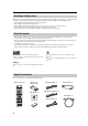
HOW TO USE THIS MANUAL Check that you have received all of the supplied accessories. (See “Supplied accessories” on page 4.) Install this unit in your listening room. (See “INSTALLING THIS UNIT IN YOUR LISTENING ROOM” on page 9.) Connect this unit to your TV and other external components. (See “CONNECTIONS” on page 11.) Prepare the remote control and turn on this unit. (See “PREPARING THE REMOTE CONTROL” on page 18 and “BASIC OPERATION” on page 19.
CONTENTS ADVANCED OPERATION OVERVIEW ........................................................... 2 MANUAL SETUP.................................................36 Selecting a listening room ......................................... 4 About this manual...................................................... 4 Supplied accessories .................................................. 4 Using SET MENU................................................... 37 SOUND MENU...............................................
OVERVIEW OVERVIEW It is generally accepted that in order to fully enjoy the benefits of surround sound at home, you must endure the agony of wiring and installing a great number of speakers in the hope that your listening room will give you the same kind of surround sound experience as your local movie theater. YAMAHA’s YSP-1 Digital Sound Projector challenges this preconception that complicated speaker set up and troublesome wiring go hand-in-hand with the enjoyment of multi-channel surround sound.
OVERVIEW The YSP-1 projects sound beams containing surround sound information for the front right (R), front left (L), surround right (SR) and surround left (SL) speaker positions, which are reflected off the walls of your listening room before reaching the actual listening position. With the addition of center (C) sound beams, this Digital Sound Projector creates true-to-life 5.1 channel surround sound that makes you feel as if there are actual speakers around the room.
OVERVIEW Selecting a listening room This unit creates surround sound by reflecting projected sound beams off the walls of your listening room. The surround sound effects produced by this unit may not be sufficient when the unit is installed in the following locations: • Rooms with surfaces inadequate for reflecting sound beams • Rooms with acoustically absorbent surfaces • Rooms with measurements outside the range: (3 to 7 m) × (2 to 3.
CONTROLS AND FUNCTIONS CONTROLS AND FUNCTIONS INTRODUCTION Front panel 1 1 Front panel display Shows information about the operational status of this unit. 2 Remote control sensor Receives signals from the remote control. 3 INPUT Switches between the connected external audio sources. 4 VOLUME –/+ Controls the output level of all audio channels (see page 30). 2 INPUT VOLUME 3 4 + STANDBY/ON 5 5 STANDBY/ON Turns on this unit or sets it in the standby mode (see page 19).
CONTROLS AND FUNCTIONS Front panel display 1 2 NIGHT SLEEP 3 PCM 4 DIGITAL PL VOL m ft mS dB 5 1 NIGHT indicator Lights up when you select a night listening mode (see page 33). 2 SLEEP indicator Lights up while the sleep timer is on (see page 50). 3 Decoder indicators When any of this unit’s decoders function, the respective indicator lights up. 6 4 Volume level indication Indicates the current volume level (see page 30).
CONTROLS AND FUNCTIONS Bottom panel RS-232C 1 2 3 4 5 INTRODUCTION SYSTEM CONNECTOR DIGITAL INPUT DVD AUX TV COAXIAL OPTICAL AUDIO INPUT VIDEO SUBWOOFER TV VCR R L R L OUT OUT 6 7 9 8 0 1 SYSTEM CONNECTOR jack Use to connect a YAMAHA subwoofer equipped with a SYSTEM CONNECTOR jack to this unit (see page 16). 6 VIDEO OUT jack Connect to your TV’s video input terminal to display this unit’s OSD (see page 12).
CONTROLS AND FUNCTIONS Remote control This section describes the function of each control on the remote control used to control this system. To operate other components, see “Controlling other components” on page 52. 1 STANDBY/ON POWER 4 NIGHT Turns on or off the night listening modes (see page 33). AV 1 2 3 4 5 6 7 8 9 0 +10 CODE SET 5 SURROUND Selects the surround mode for playback (see page 32).
INSTALLING THIS UNIT IN YOUR LISTENING ROOM INSTALLING THIS UNIT IN YOUR LISTENING ROOM This section describes how to choose a suitable installation location for this unit, and how to install the unit using either a metal wall bracket, rack or stand. Note If objects such as furniture are obstructing the path of sound beams, the desired surround sound effects may not be achieved. Make sure you install this unit where there are no objects in the path of sound beams.
INSTALLING THIS UNIT IN YOUR LISTENING ROOM Using a metal wall bracket Using a rack You can use the optional metal wall bracket to mount this system on your listening room wall. You can install this system either above or under your TV in a commercially available rack. For details on how to attach the metal bracket to the wall or how to attach this system to the metal bracket, refer to the instructions supplied with the bracket.
CONNECTIONS CONNECTIONS This unit is equipped with two optical digital jacks, one coaxial digital jack and two types of analog jacks for connecting external components such as your TV, DVD player, VCR and game console. Further, by connecting a subwoofer to this unit, you can enjoy reinforced low bass sounds. For details on how to connect the various types of external components to this unit, see pages 12 to 17.
CONNECTIONS Connecting a TV You can connect a TV to this unit and display the OSD for easy viewing (see page 20) when operating SET MENU (see page 24). When connecting the Optical Cable, use the Cable Holder at the rear panel of the YSP-1 to fix the cable (see page 15).
CONNECTIONS Connecting a DVD player/recorder To connect a DVD player/recorder, connect the coaxial digital output jack on your DVD player to the coaxial digital input jack (DVD COAXIAL) on this unit. If there is no coaxial digital output jack on your DVD player/recorder, use them with optical digital connection.
CONNECTIONS Connecting a VCR To connect a VCR, connect the analog audio output jack on your VCR to the analog audio input jack (VCR R/L) on this unit. Connect red plugs to the right jacks and white plugs to the left jacks.
CONNECTIONS Connecting other external components To connect other external components, connect the optical digital output jack on the component to the optical digital input jack (AUX OPTICAL) on this unit. You can connect a DVD player/recorder or a component that supports optical digital connections.
CONNECTIONS Connecting a subwoofer To connect a subwoofer, connect the monaural input jack on your subwoofer to the monaural audio output jack (SUBWOOFER OUT) on this unit. When connecting a YAMAHA subwoofer equipped with a SYSTEM CONNECTOR jack, connect it to the SYSTEM CONNECTOR jack on this unit. If the subwoofer is connected using a system type connection, changing the power mode of this unit controls the power mode of the subwoofer.
CONNECTIONS Connecting the power supply cable ■ Connecting the AC power cable Once all other connections are complete, plug one end of the power cable into the AC IN terminal on this unit, then plug the other end into an AC wall outlet. To an AC outlet PREPARATION About the RS-232C terminal The RS-232C terminal on the bottom panel of this unit does not support normal external component connection. This is a control expansion terminal for commercial use only.
PREPARING THE REMOTE CONTROL PREPARING THE REMOTE CONTROL Installing batteries in the remote control Press % 1 Press the mark on the battery cover and slide off the cover. 2 Insert the two supplied batteries (AA, R06, UM-3) into the battery compartment. Make sure you insert the batteries according to the polarity markings (+/–). 3 Close the battery cover.
BASIC OPERATION BASIC OPERATION Using the remote control The remote control transmits a directional infrared beam. Use the remote control within 6 m (20 feet) of this unit and point it toward the remote control sensor on the main unit during operation. Approximately 6 m (20 ft) 30˚ Turning the power on/to standby mode INPUT VOLUME + STANDBY/ON 30˚ STANDBY/ON BASIC OPERATION or POWER AV ■ Handling the remote control • Do not spill water or other liquids on the remote control.
STEPS TO ENJOYING SURROUND SOUND STEPS TO ENJOYING SURROUND SOUND This section describes very simply how to display this unit’s OSD on your TV screen and set the parameters for your listening room. Once this is complete, you can enjoy real surround sound while watching TV in the comfort of your own home. Displaying the on-screen display (OSD) Connect the video input jack on your TV to the VIDEO OUT jack on this unit to display this unit’s OSD. 1 Press STANDBY/ON on the remote control.
STEPS TO ENJOYING SURROUND SOUND Selecting a preset listening environment 1 For real surround sound, select the preset listening room type (see below) that best matches your own listening environment. If none of the selections available are suitable for your listening environment, proceed to EASY SETUP (page 24) to make your own listening environment settings. Press SET MENU. The SET MENU screen appears on your TV. The operation buttons for SET MENU are displayed at the bottom of the screen.
STEPS TO ENJOYING SURROUND SOUND 4 Press SELECT once more. The parameters for the selected room type are loaded. ;MEMORY LOAD SELECT SELECT USER1 Loading ! [<]/[>]:Select Enjoying TV in surround sound You can enjoy analog audio signals output by your TV in real surround sound. y Before performing the steps below, set this unit’s volume to –40 dB. If necessary, adjust the volume level in step 4 below. 1 Select the TV channel you want to watch.
STEPS TO ENJOYING SURROUND SOUND 5 To select a surround mode, press SURROUND repeatedly (or press SURROUND, then press / ) on this unit’s remote control. Signals input from 2-channel sources are played back on multiple channels. For more information on surround modes, see page 32. SURROUND or SURROUND SELECT BASIC OPERATION • To make more detailed listening environment settings, see page 24. • To make advanced settings for this unit, see page 36.
EASY SETUP EASY SETUP If the preset listening environment settings available in “Selecting a preset listening environment” do not match the characteristics of your listening room, follow the procedure below to set each listening environment parameter individually using EASY SETUP. ROOM TYPE > SP POSITION (Speaker position) > ROOM SIZE y • For speaker position, sound beam, digital input and display settings, see MANUAL SETUP (page 36).
EASY SETUP ■ SP POSITION (Speaker position) 4 Press SELECT once more. The display switches between the SQUARE and RECTANGLE selection screens. 6 1 ROOM TYPE ? Check that the following screen is displayed on your TV. If this screen is not displayed, make the settings in “ROOM TYPE (Room type)”. SQUARE ;EASY SETUP [<]/[>]:Select [SELECT]:Enter LE.E* SQUARE EQ. 2 SP POSITION ? LE.E3 .E4 Push [SELECT] Key.
EASY SETUP SQUARE (Square) If you selected SQUARE in “ROOM TYPE (Room type)” on page 24: CORNER (Corner left or right) RIGHT (Right) CENTER (Center) LEFT (Left) RECTANGLE (Rectangle) If you selected RECTANGLE in “ROOM TYPE (Room type)” on page 24: WIDE LEFT (Wide wall left) CORNER LEFT (Corner left) NARROW LEFT (Narrow wall left) 26 WIDE RIGHT (Wide wall right) WIDE CENTER (Wide wall center) CORNER RIGHT (Corner right) NARROW CENTER (Narrow wall center) NARROW RIGHT (Narrow wall right)
EASY SETUP ■ ROOM SIZE (Room size) 11 9 Check that the following screen is displayed on your TV. If this screen is not displayed, make the settings in “SP POSITION (Speaker position)”. Press / to select the size that best suits your listening room, then press SELECT. SELECT ;EASY SETUP SELECT LE.E* SQUARE EQ.>* CENTER LE.E3 ROOM SIZE ? LE.E4 Push [SELECT] Key. Proceed to “SETUP OK (Register settings)”. 10 BASIC OPERATION Press SELECT.
EASY SETUP SMALL (Small listening room) Approx. 3.4 m (11.2ft) 3.8 m (12.5ft) 3.8 m (12.5ft) Approx. 4.2 m (13.8ft) • Select SMALL if both the width (W) and depth (D) of your listening room are 3.8 m (12.5ft), or the width (W) is approximately 3.4 m (11.2ft) and the depth (D) approximately 4.2 m (13.8ft). MID (Medium-sized listening room) Approx. 4.6 m (15.1ft) 5.4 m (17.7ft) 5.4 m (17.7ft) Approx. 6.2 m (20.3ft) • Select MID if both the width (W) and depth (D) of your listening room are 5.4 m (17.
EASY SETUP ■ SETUP OK (Register settings) 12 • If you select NO, your EASY SETUP settings are cancelled, and the display returns to the initial SET MENU screen. Check that the following screen is displayed on your TV. If this screen is not displayed, make the settings in “ROOM SIZE (Room size)”. SET MENU ;MEMORY . ;EASY SETUP ;MANUAL SETUP LE.E* EQ..* LE.E* .
VOLUME CONTROLS VOLUME CONTROLS Adjusting the volume Muting the sound VOLUME TV VOL MUTE TV MUTE TV INPUT INPUT VOLUME + TV DVD Press MUTE. “AUDIO MUTE ON” appears in the front panel display, and the VOLUME indicator blinks. STANDBY/ON MUTE VOLUME TV VOL MUTE Remote control TV MUTE VOL TV INPUT TV DVD To increase the volume output level, press VOLUME +/–. Adjustment range: 0.0 dB to –99.
PLAYBACK PLAYBACK Selecting an input source Playing back sources You can playback sound and/or images from the various components connected to this unit simply by pressing one of the input selector buttons (TV, DVD, VCR or AUX) on the remote control. This section uses a DVD player as the playback component (source). y For details on the TV and DVD player you are using, refer to the owner’s manual supplied with your TV and DVD player.
SELECTING A SURROUND MODE SELECTING A SURROUND MODE Playback sources and their available surround modes Depending on the playback source and selected surround mode, the indicators in the front panel display light up as follows. Enjoying 2-channel sources with multi channels You can enjoy a variety of surround sound effects by switching the surround mode, including multi-channel decoding for 2-channel sources, and 5.
ADDITIONAL PLAYBACK MODES Surround mode parameters You can configure the parameters for Dolby Pro Logic II Music and DTS Neo:6 Music to fine-tune the surround sound effect. 1 Press 2 Press / / to select the parameter. to configure the parameter. PANORAMA (when selecting PLII Music) Gives front L/R channel sound a wraparound effect, distributed throughout the entire surround sound field, for an expansive feeling.
ADJUSTING BEAM MODE SETTINGS ADJUSTING BEAM MODE SETTINGS You can change the beam mode to suit the input source for this unit using the beam mode buttons. You can switch between: stereo mode for 2-channel sources, 3 beam mode and 5 beam mode and ST(STEREO)+3 beam mode for 5.1-channel playback. If you selected a wall installation type (instead of corner) for this unit in EASY SETUP – SP POSITION (page 25), or you selected wall for MANUAL SETUP – SP POSITION (page 40), all modes are available for selection.
ADJUSTING BEAM MODE SETTINGS ST(STEREO)+3 beam mode Outputs sound beams to the front left and right, center, and surround left and right speaker positions. This mode is ideal when watching live recordings on DVD. Vocals and instrumental sounds can be heard close to the center of the listening position, while sound reflections from the venue itself can be heard to your right and left, giving you the feeling that you are sitting right in front of the stage.
MANUAL SETUP MANUAL SETUP To achieve the best quality surround sound, you can use MANUAL SETUP to fine-tune the listening environment parameters, as well as make advanced settings for speaker positions, sound beams, digital input and the OSD. Change the initial settings (indicated in bold under each parameter) to reflect the needs of your own listening environment. y Most of the parameters described in SOUND MENU are set automatically when you perform EASY SETUP (see page 24).
MANUAL SETUP Using SET MENU 3 Use the remote control to access and adjust each parameter. NIGHT SURROUND Press / to select a sub menu, then press SELECT. SET MENU CH LEVEL SELECT MENU SELECT RETURN TEST VOLUME 4 y Use / / / each parameter. and SELECT to configure You can change SET MENU parameters while the unit is reproducing sound. 1 Press SET MENU. The SET MENU screen appears on your TV. The operation buttons for SET MENU are displayed at the bottom of the screen.
MANUAL SETUP SOUND MENU Use the manually adjust any speaker setting or compensate for video signal processing delays. (SET MENU → MANUAL SETUP → SOUND MENU) 1 SOUND MENU 1/2 p p . A)SUBWOOFER SET B)SPEAKER LEVEL C)DYNAMIC RANGE D)AUDIO SET [ ]/[ ]:Up/Down [SELECT]:Enter ■ SUBWOOFER SET (Subwoofer set) Use to manually adjust subwoofer settings. A)SUBWOOFER SET p p . BASS OUT;;;;;;BOTH CROSS OVER;;;100Hz LFE LEVEL;;;;;;0dB DISTANCE;;;;;;3.
MANUAL SETUP ■ DYNAMIC RANGE (Dynamic range) ■ TONE CONTROL (Tone control) Use to select the amount of dynamic range compression to be applied to the speakers. This setting is effective only when the unit is decoding Dolby Digital and DTS signals. Dynamic range is the difference between the smallest sound that can be heard above the noise of the equipment and the biggest sound that can be heard without distortion.
MANUAL SETUP BEAM MENU Use to manually adjust settings for the beams output by this unit. When you set the options in PARAMETER, related settings are automatically adjusted to suit your listening environment. (SET MENU → MANUAL SETUP → BEAM MENU) 2 BEAM MENU 1/2 Wall installation (WALL) Corner installation (CORNER) p p .
MANUAL SETUP USER POSITION (User position) Use to set the distance of the listening position from this unit. Choices: 2.0 m to 9.0 m (6.5 ft to 30.0 ft) 2.0 m to 9.0 m HORIZ. ANGLE (Horizontal angle) Use to adjust the horizontal angle of beams for each speaker. Adjust towards – (minus) to move the direction of the output to the left, and adjust towards + (plus) to move it to the right. By adjusting the horizontal angle of the beams, you can optimize the sound beam paths.
MANUAL SETUP DISTANCE (Distance) You can use this to set the distance beams travel after being output and reflected off the wall, until they arrive at the listening position for each speaker. The lines in the illustration below indicate the distance. Choices: 0.3 m to 24.0 m (1.0 ft to 80.0 ft) • FRONT L/R adjusts the distance the front left and right speaker sound beams travel. • CENTER adjusts the distance the center speaker sound beams travel.
MANUAL SETUP ■ IMAGE LOCATION (Image location) ■ MEMORY (User memory) You can adjust the direction from which front left and right speaker sound is heard by directing these audio signals so that they are also output from the center speaker. Use this feature to redirect audio signals if the sound coming from the left and right speakers seems unnatural, such as when your listening position is not the center of your listening room.
MANUAL SETUP ■ INPUT MODE (Input mode) INPUT MENU Use to reassign digital input from external components connected to this unit. (SET MENU → MANUAL SETUP → INPUT MENU) Use this feature to designate the input mode for sources connected to the DIGITAL INPUT jacks when you turn on this unit. For information on the types of audio signals that can be output by this unit, see “Surround Modes and Recommended Usages” on page 32. Choices: AUTO, LAST 3 INPUT MENU B)INPUT MODE )AUTO p p .
MANUAL SETUP 3 Press / to select the character you want. • You can use up to 8 characters for each input. • Press to change the character in the following order, or press to go in the reverse order: A to Z, a space, 0 to 9, a space, a to z, a space, #, *, +, etc. OPTION MENU You can use this menu to adjust the optional system parameter, such as OSD settings and the display unit of measurement. (SET MENU → MANUAL SETUP → OPTION MENU) 4 OPTION MENU p p .
MANUAL SETUP ■ UNIT SET (Unit settings) You can use this to change the display unit of measurement. Choices: METERS, FEET B)UNIT SET )METERS FEET [<]/[>]:Select [SELECT]:Retern • Select METERS to input speaker distances in meters. • Select FEET to input speaker distances in feet.
SELECTING AN INPUT MODE SELECTING AN INPUT MODE You can select the type of input signals you want this unit to use. • AUTO Automatically selects input signals in the following order: 1) Digital signals 2) Analog signals Use this input mode in most cases. INPUT VOLUME + • DTS Selects only digital signals encoded in DTS. Compared to AUTO, this input mode provides greater stability during playback.
MANUALLY ADJUSTING OUTPUT LEVELS MANUALLY ADJUSTING OUTPUT LEVELS You can adjust the output level of each speaker to achieve a more true-to-life surround sound experience. You can adjust the sound beam output levels for each beam mode. Using the test tone 3 You can use the test tone feature to output a test tone from each speaker to manually balance the speaker levels. Use the test tone to set speaker levels, so that the volume from each speaker is identical when heard from your listening position.
MANUALLY ADJUSTING OUTPUT LEVELS Adjusting output levels during playback You can also manually adjust the speaker levels while playing back a source, such as a DVD. NIGHT SURROUND 4 Press CH LEVEL when you have completed your adjustment. CH LEVEL SET MENU CH LEVEL MENU SELECT RETURN TEST O 1 Press CH LEVEL. CH LEVEL 2 Press / to adjust. 3 Press / to adjust speaker volumes.
USING THE SLEEP TIMER USING THE SLEEP TIMER Use this feature to automatically set this unit in the standby mode after a specified time period. The sleep timer is useful when you are going to sleep while this unit is playing a source. ■ Setting the sleep timer ■ Canceling the sleep timer You can deactivate the sleep timer setting as follows. RETURN TEST VOLUME TV VOL 1 MUTE Press SLEEP repeatedly until “SLEEP OFF” appears in the front panel display.
REMOTE CONTROL FEATURES REMOTE CONTROL FEATURES In addition to controlling this unit, the remote control can also operate other A/V components made by YAMAHA and other manufacturers. To control other components, you must set up the remote control with the appropriate remote control codes. Note Depending on the external AV component you are using, you may not be able to operate the component with this unit’s remote control, even if a remote control code is set.
REMOTE CONTROL FEATURES Controlling other components ■ Operating your TV ■ Operating your DVD player STANDBY/ON AV 2 STANDBY/ON POWER 1 2 3 5 6 7 POWER 1 AV 4 2 8 1 2 3 5 6 7 3 0 4 8 CODE SET CODE SET 9 1 9 +10 0 +10 CH CH 3 NIGHT SURROUND NIGHT SET MENU CH LEVEL CH LEVEL MENU 5 SELECT RETURN TEST SET MENU MENU 4 SELECT RETURN TEST VOLUME TV VOL SURROUND 6 VOLUME TV VOL MUTE MUTE TV MUTE TV MUTE 4 6 TV INPUT TV DVD SLEEP AUX VCR 5 TV
REMOTE CONTROL FEATURES ■ Operating your VCR player STANDBY/ON POWER AV 2 ■ Returning to theYSP-1 operation mode 1 2 3 5 6 7 1 4 8 CODE SET 9 3 0 +10 CH 4 NIGHT SURROUND CH LEVEL To return to the YSP-1 operation mode, press one of the following keys. For details on each key, see page 8 or 20. NIGHT SURROUND SET MENU CH LEVEL TEST SET MENU MENU SELECT RETURN TEST VOLUME TV VOL MUTE TV MUTE TV INPUT TV DVD SLEEP AUX VCR VCR Press VCR to switch the input to VCR.
TROUBLESHOOTING TROUBLESHOOTING Refer to the chart below when this unit does not function properly. If the problem you are experiencing is not listed below or if the instruction below does not help, set this unit to the standby mode, disconnect the power cord, and contact the nearest authorized YAMAHA dealer or service center. ■ General Problem Cause Remedy Refer to page This unit fails to turn on when STANDBY/ ON is pressed, or enters the standby mode soon after the power has been turned on.
TROUBLESHOOTING Problem Cause Remedy Refer to page Surround sound effects are insubstantial. The listening room is not a regular shape. Install this unit in a square or rectangular shaped room. — There is no wall in the path of the beam. Place a flat object, such as a board, in the path of the beam. — Dolby Digital or DTS sources cannot be played. (Dolby Digital or DTS indicator in the front panel display does not light up.
TROUBLESHOOTING ■ Remote control Problem The remote control does not work and/or function properly. You cannot operate external components with this unit’s remote control. The cursor buttons do not work during SET MENU operation. 56 Cause Remedy Refer to page Wrong distance or angle. The remote control will function within a maximum range of 6 m (20 ft) and no more than 30 degrees offaxis from the front panel. 19 Direct sunlight or lighting (from an inverter type of fluorescent lamp, etc.
RESETTING THE FACTORY PRESETS RESETTING THE FACTORY PRESETS If you want to reset all of your unit’s parameters for any reason, do the following. This procedure completely resets ALL the parameters in SET MENU. 3 Note After performing the following procedure you must reset the ROOM TYPE, SP POSITION and ROOM SIZE parameters to match your surround sound environment. Press INPUT once more. “RESET” appears in the front panel display.
FRONT PANEL DISPLAY ITEMS FRONT PANEL DISPLAY ITEMS ■ POWER STANDBY/ON VOLUME -40.
GLOSSARY GLOSSARY Audio formats ■ Dolby Digital Dolby Digital is a digital surround sound system that gives you completely independent multi-channel audio. With 3 front channels (left, center, and right), and 2 surround stereo channels, Dolby Digital provides 5 full-range audio channels. With an additional channel especially for bass effects, called LFE (low frequency effect), the system has a total of 5.1-channels (LFE is counted as 0.1 channel).
INDEX INDEX A Audio Pin Cable ............................................................. 12 B Beam modes ................................................................... 34 C Coaxial digital output jack ............................................. 13 Coaxial digital input jack ............................................... 13 D Digital Audio Pin Cable ................................................. 13 Display........................................................................
SPECIFICATIONS SPECIFICATIONS AMP SECTION • Maximum Output Power (EIAJ) ................................................2 W (1 kHz, 10% THD, 10 Ω) × 40 20 W (100 Hz, 10% THD, 4 Ω) × 2 SPEAKER SECTION Small dia. speakers ............................... 4 cm (1.5”)-cone magnetic shielding type× 40 Woofers................. 11 cm (4.5”)-cone magnetic shielding type × 2 • Input Jacks AUDIO VCR, TV (Analog) (1 V, 32 kΩ)............. 2 pairs (Analog) AUDIO AUX, TV (Optical) ......................................
LIST OF REMOTE CONTROL CODES TV ADMIRAL 292, 293, 216 AIWA 294, 276, 283, 284 AKAI 295, 296 ALBA 296 AOC 297 BELL & HOWELL 292 BESTAR 298 BLAUPUNKT 229, 222 BLUE SKY 298 BRANDT 223 BROC SONIC 297 BUSH 296 CLATRONIC 298 CRAIG 224 CROSLEX 225 CURTIS MATHIS 297, 226 DAEWOO 297, 298, 224, 227, 228 DAYTRON 239 DUAL 298 DWIN 293, 281 EMERSON 297, 224, 239, 232 FURGUSON 223, 265, 266 FIRST LINE 298 FISHER 295, 233 FRABA 298 FUJITSU 289 FUNAI 277, 278 GE 293, 297, 234, 235, 236 GOODMANS 296, 298, 223 GRUNDIG 229,
CABLE ABC 739, 752, 753, 755, 758, 759, 762 GENERAL INSTRUMENT 722 HAMIN 723, 724, 725, 726, 727 HITACHI 722 JEROLD 722, 728, 729, 732, 733, 734, 735, 736, 737 MAGNAVOX 738 MOTOROLA 748 OAK 739, 742, 743 PANASONIC 744, 745, 746, 747 PHILLIPS 763, 764, 765, 766, 767, 768 PIONEER 748 RADIO SHACK749 SCIENTIFIC ATLANTA 752, 753, 754 SONY 756, 757 TOCOM 755 UNIVERSAL 769, 772, 773, 774, 775 VIEWSTAR 764, 766, 776, 777, 778, 779, 782 SATELLITE TUNER ECHOSTAR 822 GE 837, 838, 839 GENERAL INSTRUMENT 823 HITACHI 8
© 2004 YAMAHA ELECTRONICS CORPORATION, USA 6660 ORANGETHORPE AVE., BUENA PARK, CALIF. 90620, U.S.A. YAMAHA CANADA MUSIC LTD. 135 MILNER AVE., SCARBOROUGH, ONTARIO M1S 3R1, CANADA YAMAHA ELECTRONIK EUROPA G.m.b.H. SIEMENSSTR. 22-34, 25462 RELLINGEN BEI HAMBURG, GERMANY YAMAHA ELECTRONIQUE FRANCE S.A. RUE AMBROISE CROIZAT BP70 CROISSY-BEAUBOURG 77312 MARNE-LA-VALLEE CEDEX02, FRANCE YAMAHA ELECTRONICS (UK) LTD. YAMAHA HOUSE, 200 RICKMANSWORTH ROAD WATFORD, HERTS WD18 7GQ, ENGLAND YAMAHA SCANDINAVIA A.B.