
Service manual


YSP-1
9
YSP-1
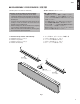
3. INPUT(2)P.C.B.の外し方
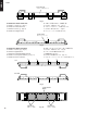
3. Removal of INPUT (2) P.C.B.
a. Remove 14 screws (4). (Fig. 4)
b. Remove 3 pad L’s. (Fig. 4)
c. Remove the Plate/Shield.
d. Remove 4 screws (5). (Fig. 5)
e. Remove CB7, CB9 and CB302. (Fig. 5)
f. Remove the INPUT (2) P.C.B..
4 44
44
4
Plate/ Shield
Pad L
Fig. 4
4. DSP P.C.B.、AMP P.C.B.の外し方
4. Removal of DSP P.C.B., AMP P.C.B.
a. Remove 4 screws (6). (Fig. 6)
b. Remove CB3 and CB303. (Fig. 6)
c. Remove DSP P.C.B..
d. Remove 8 screws (7). (Fig. 6)
e. Remove CB1, CB2, CB4, CB5 and CB6. (Fig. 6)
f. Remove AMP P.C.B.s.
5
5
INPUT (2) P.C.B.
CB7
CB9
CB302
CB7
Fig. 5
Fig. 6
6
6
CB1
CB303
CB6 CB1
CB2 CB5 CB4
7
7
7
7
CB6 CB3 CB4CB3 CB2CB5
DSP P.C.B.
AMP P.C.B.
AMP P.C.B.