YSP-1100_UAB-cv.fm Page 1 Friday, August 11, 2006 4:42 PM UAB YSP-1100 Digital Sound Projector © 2006 YAMAHA ELECTRONICS CORPORATION, USA 6660 ORANGETHORPE AVE., BUENA PARK, CALIF. 90620, U.S.A. YAMAHA CANADA MUSIC LTD. 135 MILNER AVE., SCARBOROUGH, ONTARIO M1S 3R1, CANADA YAMAHA ELECTRONIK EUROPA G.m.b.H. SIEMENSSTR. 22-34, 25462 RELLINGEN BEI HAMBURG, GERMANY YAMAHA ELECTRONIQUE FRANCE S.A. RUE AMBROISE CROIZAT BP70 CROISSY-BEAUBOURG 77312 MARNE-LA-VALLEE CEDEX02, FRANCE YAMAHA ELECTRONICS (UK) LTD.
IMPORTANT SAFETY INSTRUCTIONS IMPORTANT SAFETY INSTRUCTIONS CAUTION RISK OF ELECTRIC SHOCK DO NOT OPEN CAUTION: TO REDUCE THE RISK OF ELECTRIC SHOCK, DO NOT REMOVE COVER (OR BACK). NO USER-SERVICEABLE PARTS INSIDE. REFER SERVICING TO QUALIFIED SERVICE PERSONNEL.
IMPORTANT SAFETY INSTRUCTIONS FCC INFORMATION (for US customers) 1. IMPORTANT NOTICE: DO NOT MODIFY THIS UNIT! This product, when installed as indicated in the instructions contained in this manual, meets FCC requirements. Modifications not expressly approved by YAMAHA may void your authority, granted by the FCC, to use the product. Compliance with FCC regulations does not guarantee that interference will not occur in all installations.
CAUTION: READ THIS BEFORE OPERATING THIS UNIT. CAUTION: READ THIS BEFORE OPERATING THIS UNIT. 1 2 3 4 5 6 7 8 9 10 11 12 13 14 15 16 17 18 19 20 21 To assure the finest performance, please read this manual carefully. Keep it in a safe place for future reference. Install this sound system in a well ventilated, cool, dry, clean place with at least 5 cm of space above (or below) this unit – away from direct sunlight, heat sources, vibration, dust, moisture, and/or cold.
01EN_YSP-1100_UAB_EN.book Page 1 Wednesday, August 30, 2006 1:46 PM CONTENTS OVERVIEW ........................................................... 2 FEATURES............................................................. 3 USING THIS MANUAL ........................................ 4 SUPPLIED ACCESSORIES ................................. 5 CONTROLS AND FUNCTIONS ......................... 6 PREPARATION INSTALLATION ................................................. 11 Before installing this unit................
OVERVIEW OVERVIEW It is generally accepted that in order to fully enjoy the benefits of surround sound at home, you must endure the agony of wiring and installing a great number of speakers in the hope that your listening room will give you the same kind of surround sound experience as your local movie theater. YAMAHA YSP-1100 Digital Sound Projector challenges this preconception that complicated speaker setup and troublesome wiring go hand-in-hand with the enjoyment of multi-channel surround sound.
FEATURES FEATURES My beam This unit employs the my beam so that you can achieve a clear sound in noisy environment. You can adjust the beam angle manually or automatically using the supplied remote control. Cinema DSP Digital This unit employs the Cinema DSP Digital technology developed by YAMAHA Electronics Corp. so that you can experience movies at home with all the dramatic sound impact that the director intended to convey.
USING THIS MANUAL USING THIS MANUAL Notes • This manual describes how to connect and operate this unit. For details regarding the operation of external components, refer to the supplied owner’s manual for the component. • Some operations can be performed by using either the buttons on the main unit or on the remote control. In such cases, the operation is described using remote control operation. • y indicates a tip for your operation. • This manual is printed prior to production.
SUPPLIED ACCESSORIES SUPPLIED ACCESSORIES Remote control (×1) Optical cable (×1) POWER POWER STANDBY/ON AV STB Batteries (×2) (AA, R6, UM-3) INTRODUCTION Check that you have received all of the following parts.
01EN_YSP-1100_UAB_EN.book Page 6 Wednesday, August 30, 2006 1:46 PM CONTROLS AND FUNCTIONS CONTROLS AND FUNCTIONS Front panel 1 2 INPUT VOLUME 4 5 1 OPTIMIZER MIC jack Use to connect the supplied optimizer microphone to be used to run AUTO SETUP (see page 30). 2 Front panel display Shows information about the operational status of this unit. 3 Remote control sensor Receives infrared signals from the remote control. 4 INPUT Press repeatedly to switch between input sources (TV, VCR, DVD or AUX).
CONTROLS AND FUNCTIONS Front panel display 2 NIGHT SLEEP 3 PCM INTRODUCTION 1 4 DIGITAL PL VOL m ft mS dB 5 1 NIGHT indicator Lights up when one of the night listening modes is selected (see page 55). 2 SLEEP indicator Lights up when the sleep timer is turned on (see page 58). 3 Decoder indicators Light up when the corresponding decoder of this unit is in operation (see page 44). 4 Volume level indicator Shows the current volume level (see page 41).
CONTROLS AND FUNCTIONS Rear panel E 1 2 DVD COAXIAL RS-232C REMOTE IN 3 4 AUX TV/STB OPTICAL DIGITAL IN 5 TV/STB 6 7 VCR AUDIO IN 1 RS-232C/REMOTE IN terminals These are control expansion terminals for factory use only (see page 23). 2 DVD COAXIAL DIGITAL IN jack Use to connect a DVD player/recorder via a coaxial digital connection (see page 17). 3 AUX OPTICAL DIGITAL IN jack Use to connect an external component via an optical digital connection (see page 21).
CONTROLS AND FUNCTIONS Remote control y You can also control other components using the remote control once you set the appropriate remote control codes. See “Controlling other components” on page 82 for details. 1 Infrared window Outputs infrared control signals. Aim this window at the component you want to operate. 2 STANDBY/ON Sets this system to the standby mode (see page 25). 3 Transmission indicator Lights up when infrared control signals are being output.
CONTROLS AND FUNCTIONS H TV POWER Turns on the power of the TV or sets it to the standby mode (see page 82). I AV POWER Turns on the power of the selected component or sets it to the standby mode (see pages 82 and 83). J INPUT1/INPUT2 Selects the input source of the TV (see page 82). K MACRO Use to set the TV macro (see page 84). L SLEEP Sets the sleep timer (see page 58). M INPUTMODE Switches between input modes (AUTO, DTS or ANALOG). See page 75 for details.
INSTALLATION INSTALLATION This section describes a suitable installation location to install the unit using a metal wall bracket, a rack or a stand. Before installing this unit Installing this unit Install this unit where there are no obstacles such as furniture obstructing the path of sound beams. Otherwise, the desired surround sound effects may not be achieved. You may install this unit in parallel with the wall or in the corner.
INSTALLATION ■ Installation examples Example 1 Install this unit as close to the exact center of the wall as possible. Example 2 Install this unit so that the sound beams can be reflected off the walls. Example 3 Install this unit as close to the exact front of your normal listening position.
INSTALLATION ■ Using a metal wall bracket ■ Using a TV stand You can use the optional metal wall bracket to mount this unit on the wall in your listening room. You can use the optional TV stand to install this unit. For detailed information on installing this unit using a TV stand, refer to the installation manual supplied with the optional TV stand.
INSTALLATION ■ Affixing this unit Peel off the film from each of the four supplied fasteners and then secure them to the bottom four corners of this unit and the top of the rack, etc. This unit Peel off the pad on the bottom Peel off the film 2 Fasteners 1 Notes • Do not install this unit on top of a slanted surface. This unit may fall over and cause injury. • Make sure you wipe the surface of the rack, etc. before securing the fasteners.
CONNECTIONS CONNECTIONS This unit is equipped with the following types of audio/video input/output jacks: For audio input • 2 optical digital input jacks • 1 coaxial digital input jack • 2 sets of analog input jacks For video input • 3 composite analog input jacks • 2 sets of component analog input jacks For video output • 1 composite analog output jack • 1 set of component analog output jacks CAUTION Do not connect this unit or other components to the main power until all connections between components
CONNECTIONS Connecting a TV Connect a TV to this unit and display the OSD for easy viewing when you adjust the system parameters in SET MENU. ■ Audio connections ■ Video connections Connect the analog audio output jacks of your TV to the TV/STB AUDIO IN jacks of this unit. If your TV has an optical digital output jack, connect the optical digital output jack of your TV to the TV/STB OPTICAL DIGITAL IN jack of this unit in addition to the analog audio connection.
01EN_YSP-1100_UAB_EN.book Page 17 Wednesday, August 30, 2006 1:46 PM CONNECTIONS Connecting a DVD player/recorder Connect a DVD player/recorder and enjoy DVDs. ■ Video connections Connect the optical digital output jack of your DVD player/recorder to the DVD COAXIAL DIGITAL IN jack of this unit.
CONNECTIONS Connecting a VCR Connect a VCR and enjoy video cassette tapes. ■ Audio connections ■ Video connections Connect the analog audio output jacks of your VCR to the VCR AUDIO IN jacks of this unit. Connect the video output jack of your VCR to the VCR VIDEO IN jack of this unit. Note Be sure to match the left and right output jacks of your VCR with the left and right input jacks of this unit.
01EN_YSP-1100_UAB_EN.book Page 19 Wednesday, August 30, 2006 1:46 PM CONNECTIONS Connecting a digital satellite tuner or a cable TV tuner Connect a digital satellite tuner or a cable TV tuner and enjoy digital satellite broadcasting or cable TV broadcasting. ■ Video connections Connect the optical digital output jack of your digital satellite tuner or cable TV tuner to the TV/STB OPTICAL DIGITAL IN jack of this unit.
01EN_YSP-1100_UAB_EN.book Page 20 Wednesday, August 30, 2006 1:46 PM CONNECTIONS Connecting a digital airwave tuner If your digital airwave tuner does not support analog broadcasting, make audio/video connections as shown below. ■ Audio connections ■ Video connections Connect the optical digital output jack of your digital airwave tuner to the TV/STB OPTICAL DIGITAL IN jack of this unit.
01EN_YSP-1100_UAB_EN.book Page 21 Wednesday, August 30, 2006 1:46 PM CONNECTIONS Connecting other external components To connect other external components, connect the optical digital output jack of an external component to the AUX OPTICAL DIGITAL IN jack of this unit. Use this connection method to connect an external component that supports an optical digital connection or to connect a DVD player/recorder via an optical digital connection.
CONNECTIONS Connecting a subwoofer To connect a subwoofer, connect the monaural input jack of your subwoofer to the SUBWOOFER jack of this unit. If a subwoofer is connected to this unit, turn on the power of your subwoofer and then run AUTO SETUP (see page 29) or select SWFR for BASS OUT in SUBWOOFER SET (see page 67).
CONNECTIONS Connecting the power supply cable Once all other connections are complete, plug one end of the power supply cable into the AC IN terminal of this unit and then plug the other end into the AC wall outlet. To the AC outlet PREPARATION About the RS-232C/REMOTE IN/IR-OUT terminals The RS-232C, REMOTE IN and IR-OUT terminals do not support normal external component connections. These are control expansion terminals for factory use only.
GETTING STARTED GETTING STARTED Installing batteries in the remote control y Remove the transparent sheet before using the remote control. Press Operation range of the remote control 1 Press and hold the mark on the battery cover and then slide off the cover. 2 Insert the two supplied batteries (AA, R6, UM-3) into the battery compartment. Make sure you insert the batteries according to the polarity markings (+/–). 3 The remote control transmits a directional infrared beam.
GETTING STARTED Using the remote control Turning on the power This section describes how to control this unit using the supplied remote control. The functions of the remote control change depending on the position of the operation mode selector. Set the operation mode selector to YSP to switch to the operation mode of this unit. The buttons on the remote control numbered 1 to 4 are operational only when you select YSP.
USING SET MENU USING SET MENU Displaying the OSD This section simply describes how to display the OSD (on-screen display) of this unit on your TV screen and set the parameters for your listening room. Once this is complete, you can enjoy real surround sound while watching TV in the comfort of your own home. Note The OSD is not output at the COMPONENT VIDEO OUT jacks of this unit. Connect the VIDEO OUT jack of this unit to the video input jacks of your TV to display the OSD.
USING SET MENU The flow chart of SET MENU The following diagram illustrates the overall flow of the setup procedure. Run LANGUAGE SETUP. See “CHANGING OSD LANGUAGE” on page 28. Run AUTO SETUP (IntelliBeam). See “AUTO SETUP (IntelliBeam)” on page 29. If an error occurs SETUP Look for a remedy. See “Error messages for AUTO SETUP” on page 35 for a complete list of error messages and possible remedies. Play back audio signals or adjust the settings for the beam mode and the CINEMA DSP.
CHANGING OSD LANGUAGE CHANGING OSD LANGUAGE This feature allows you to select the language of your choice that appears in the SET MENU of this unit. 1 Set the operation mode selector to YSP to switch to the operation mode of this unit. 4 Press / to select the language and then press ENTER. TV/AV YSP ENTER 2 Press MENU on the remote control. The SET MENU screen appears on your TV. SET MENU MENU .
AUTO SETUP (INTELLIBEAM) AUTO SETUP (IntelliBeam) This unit creates a sound field by reflecting sound beams on the walls of your listening room and broadening the cohesion of all the channels. Just as you would arrange the speaker position of other audio systems, you need to set the beam angle to enjoy the best possible sound from this unit.
AUTO SETUP (IntelliBeam) Installing the optimizer microphone The supplied optimizer microphone collects and analyzes the sound that this unit produces in your actual listening environment. Follow the procedure below to connect the optimizer microphone to this unit and make sure that the optimizer microphone is placed in a proper location and that there are no large obstacles between the optimizer microphone and the walls in your listening room.
AUTO SETUP (IntelliBeam) Using AUTO SETUP (IntelliBeam) Once the optimizer microphone is firmly connected to this unit and properly placed in your listening room, follow the procedure below to start the AUTO SETUP procedure. You can also enter the AUTO SETUP procedure simply by pressing and holding AUTO SETUP on the remote control more than 2 seconds. In this case, this unit performs both of the beam optimization and sound optimization procedures.
AUTO SETUP (IntelliBeam) 3 Notes • Make sure that your listening room is as quiet as possible while this unit is performing the AUTO SETUP procedure. • To achieve the best results possible, evacuate yourself from your listening room until the AUTO SETUP procedure is completed so that you may not obstruct the path of sound beams. • Be advised that it is normal for loud test tones to be output during the AUTO SETUP procedure.
01EN_YSP-1100_UAB_EN.book Page 33 Wednesday, August 30, 2006 1:46 PM AUTO SETUP (IntelliBeam) 5 Press / to select BEAM+SOUND OPTIMZ, BEAM OPTIMZ only or SOUND OPTIMZ only and then press ENTER. The following screen appears on your TV. ENTER 6 Check the following points once again before starting the AUTO SETUP procedure.
AUTO SETUP (IntelliBeam) 8 Check that the following screen is displayed on your TV. The results of the AUTO SETUP procedure are displayed on your TV. 10 Disconnect the optimizer microphone from the OPTIMIZER MIC jack on the front panel. Side view Example 1 SHOW RESULT MEASUREMENT COMPLETE BEAM MODE :5 BEAM SUBWOOFER :NOT APPLICABLE [ENTER]:Save set-up. [RETURN]:Do not save set-up.
01EN_YSP-1100_UAB_EN.book Page 35 Wednesday, August 30, 2006 1:46 PM AUTO SETUP (IntelliBeam) ■ Error messages for AUTO SETUP Before the AUTO SETUP procedure starts Error message ERROR E-2 No MIC Detected. Please check MIC connection and re-try. Cause The optimizer microphone is not connected to this unit. Remedy Connect the optimizer microphone to this unit. See page 30 While the AUTO SETUP procedure is in progress If one of the errors shown below except E-1 is displayed, press RETURN.
USING THE SYSTEM MEMORY USING THE SYSTEM MEMORY Convenient usage of the system memory 3 You can save the current settings adjusted in SET MENU in the system memory of this unit. It is handy to save certain settings according to the varying conditions of your listening environment. For example, if there are curtains in the path of beams, the effectiveness of the beams will vary depending on whether the curtains are open or closed. When the curtains are open Press / to select MEMORY and then press ENTER.
USING THE SYSTEM MEMORY 5 Press / to select MEMORY1, MEMORY2 or MEMORY3 and then press ENTER. The following screen appears on your TV. Loading settings You can recall the settings saved in “Saving settings” on page 36 according to the varying conditions of your listening environment. 1 ENTER ENTER Set the operation mode selector to YSP to switch to the operation mode of this unit. TV/AV YSP 2)MEMORY SAVE 2 Press MENU on the remote control. The SET MENU screen appears on your TV.
USING THE SYSTEM MEMORY 4 Press / to select LOAD and then press ENTER. The following screen appears on your TV. 6 Press ENTER again. The new parameters are saved as MEMORY1, MEMORY2 or MEMORY3. Once the parameters are saved, the display returns to the SET MENU screen. 1)MEMORY LOAD ENTER ENTER MEMORY1 Loading ENTER 1)MEMORY LOAD p MEMORY1 MEMORY2 MEMORY3 SET MENU .
PLAYBACK PLAYBACK Selecting the input source You can play back sound from the components connected to this unit simply by pressing INPUT on the front panel repeatedly or pressing one of the input selector buttons (TV, STB, VCR, DVD or AUX) on the remote control. The name of the selected input source and the type of the corresponding input mode appear in the front panel display. ■ Front panel operations Press INPUT on the front panel repeatedly to toggle between TV, DVD, VCR and AUX.
01EN_YSP-1100_UAB_EN.book Page 40 Wednesday, August 30, 2006 1:46 PM PLAYBACK Set the operation mode selector to YSP to switch to the operation mode of this unit and then press VCR on the remote control to play back a video tape. TV/AV VCR Playing back sources Once an input source is selected (see page 39), you can play back the selected input source. Note YSP This section uses a DVD player as an example of the playback source.
PLAYBACK Adjusting the volume Muting the sound VOLUME CH TV VOL MUTE TV INPUT TV MUTE CODE SET 1 INPUT VOLUME + STANDBY/ON Press MUTE on the remote control to mute the sound. AUDIO MUTE ON appears in the front panel display, and the volume level indicator flashes. MUTE VOLUME CH TV VOL MUTE TV INPUT TV MUTE VOL CODE SET Flashes VOL 2 VOLUME or VOLUME + Front panel Press MUTE on the remote control again (or press VOLUME +/–) to resume the sound output.
01EN_YSP-1100_UAB_EN.book Page 42 Wednesday, August 30, 2006 1:46 PM ENJOYING SURROUND SOUND ENJOYING SURROUND SOUND You can enjoy multi channel surround sound by changing the beam mode using the beam mode buttons on the remote control. Select 3 beam, 5 beam and stereo plus 3 beam for multi channel playback. Note When ANGLE TO WALL OR CORNER is set in MANUAL SETUP (see page 62), 5 beam and 3 beam cannot be selected.
01EN_YSP-1100_UAB_EN.book Page 43 Wednesday, August 30, 2006 1:46 PM ENJOYING SURROUND SOUND Stereo plus 3 beam 3 beam Outputs normal sound from the front left and right channels and sound beams from the center and surround left and right channles. This mode is ideal for watching live recordings on a DVD.
ENJOYING SURROUND SOUND ■ Decoder indicators Depending on the input source and the selected surround mode, the indicators in the front panel display light up as follows: Status When PCM signals are being input Indicator PCM When DTS digital signals are being input or when DTS Neo:6 is selected When Dolby Digital signals are being input When Dolby Pro Logic is selected When Dolby Pro Logic II is selected Recommended source Surround mode Dolby Pro Logic – All sources Dolby Pro Logic II Movie Music G
ENJOYING SURROUND SOUND Enjoying 2-channel sources in surround sound This unit can decode 2-channel sources for 5.1 channel playback so that you can enjoy a variety of surround sound effects by switching the surround mode. 2 Press SURROUND on the remote control repeatedly (or press SURROUND and then press / ) to switch between surround modes.
ENJOYING SURROUND SOUND Adjusting surround mode parameters You can configure the parameters for Dolby Pro Logic II Music and DTS Neo:6 Music to fine-tune the surround sound effect. 5BEAM ST+3BEAM 3BEAM 1 2 3 STEREO MY BEAM SURROUND 4 5 6 MUSIC MOVIE SPORTS 7 8 9 OFF 0 +10 CH LEVEL MENU TV/AV ENTER YSP RETURN TEST 1 2 Repeat steps 1 and 2 in “Enjoying 2-channel sources in surround sound” on page 45 and select PL II Music or Neo:6 Music. Press / to select the parameter.
ENJOYING STEREO SOUND ENJOYING STEREO SOUND Stereo playback Notes You can enjoy 2-channel stereo playback by changing the beam mode to the stereo playback using the beam mode buttons on the remote control. The normal sounds are output from the front and left channels in the 2-channel stereo. This is ideal for playing back hi-fi sources, such as CDs, and can be used to replace your TV speakers.
PLAYING BACK SOUND CLEARLY (MY BEAM) PLAYING BACK SOUND CLEARLY (My beam) You can improve listenability in a noisy environment by changing the beam mode to the my beam, outputs sound beams directly to the listening position in a single channel. In addition, the my beam is also ideal if you do not want the sound beams to be reflected on the walls in your listening room or if you do not disturb others asleep while enjoying music or movies at night.
PLAYING BACK SOUND CLEARLY (My beam) Using manual-adjust function You can adjust the beam angle manually while playing back an input source. This function is also ideal if the listening position is out of the operation guarantee range of the auto-adjust function. 1 Set the operation mode selector to YSP to switch to the operation mode of this unit. TV/AV YSP 2 Press MY BEAM on the remote control. MY BEAM is displayed in the front panel display.
USING SOUND FIELD PROGRAMS USING SOUND FIELD PROGRAMS This unit is equipped with a variety of precise digital decoders that allow you to enjoy multi-channel playback from stereo or multi-channel sources. This unit is also equipped with a YAMAHA CINEMA DSP (digital sound field processing) chip containing several sound field programs which you can use to enhance your playback experience.
USING SOUND FIELD PROGRAMS Sound field program descriptions You can select from the following sound field programs based on your listening preference when you play music, movie or sports sources. For details on how to switch between the available sound field programs, see page 52. Note There is only one sports sound field program available. Sound field program Source Feature Music Video This program produces a vibrant environment and lets you feel as if you are at an actual jazz or rock concert.
USING SOUND FIELD PROGRAMS Turning on CINEMA DSP programs 3 You can select from three different sound field programs (MUSIC, MOVIE and SPORTS) depending on the type of sources you want to enjoy. Check that MUSIC is displayed in the front panel display and then press MUSIC on the remote control repeatedly (or press / on the remote control) to switch between the music sound field programs.
USING SOUND FIELD PROGRAMS 3 Check that MOVIE is displayed in the front panel display and then press MOVIE on the remote control repeatedly (or press / on the remote control) to switch between the music sound field programs. VOL MOVIE or 8 ENTER Sci-Fi Spectacle Adventure y For detailed descriptions of each sound field program, see “Sound field program descriptions” on page 51. BASIC OPERATION ■ Sports program Select this sound field program when you play sports sources.
USING SOUND FIELD PROGRAMS Turning off CINEMA DSP programs Adjusting CINEMA DSP effect levels Turn off the CINEMA DSP programs if you want to enjoy the original sound without the sound field program effect. You can enjoy good quality sound with the factory preset parameters. However, you can also adjust the effect level of the CINEMA DSP programs relative to the level of the direct sound so that each sound field program can reflect your listening environment and your preference even more accurately.
USING THE VOLUME MODE (NIGHT LISTENING MODE/TV VOLUME EQUAL MODE) USING THE VOLUME MODE (Night listening mode/TV volume equal mode) The night listening modes are designed to improve listenability at lower volumes or at night. In addition, you can limit the volume level of the TV so that it will not vary suddenly to a great extent whenever the contents being broadcast change (i.e. due to commercials, etc.).
USING THE VOLUME MODE (Night listening mode/TV volume equal mode) 3 Press / on the remote control to adjust the effect level of compression while NIGHT:CINEMA, NIGHT:MUSIC or TV EQUAL VOL is displayed. ENTER Effect.Lvl:MIN Effect.Lvl:MID Effect.Lvl:MAX • Select Effect.Lvl:MIN for minimum compression. • Select Effect.Lvl:MID for standard compression. • Select Effect.Lvl:MAX for maximum compression.
USING BASS SOUND ENHANCER (TRUBASS) USING BASS SOUND ENHANCER (TruBass) This unit can produce the perception of an improved low frequency performance with the aid of the SRS TruBass technology, which improves bass even without a subwoofer and provides deeper, richer bass in the presence of a subwoofer. Note The TruBass is not available when the my beam is selected as the beam mode (see page 48).
USING THE SLEEP TIMER USING THE SLEEP TIMER Use this feature to automatically set this unit to the standby mode after a specified time period. The sleep timer is useful if you are going to sleep after a certain amount of time while this unit is still playing back a source. Each time you press SLEEP on the remote control, the front panel display changes as shown below.
USING THE SLEEP TIMER Canceling the sleep timer 1 Set the operation mode selector to YSP to switch to the operation mode of this unit. TV/AV YSP 2 Press SLEEP on the remote control repeatedly so that SLEEP OFF appears in the front panel display. SLEEP VOL SLEEP 3 OFF BASIC OPERATION Wait for a few seconds without operating this unit to confirm the setting for the sleep timer. The SLEEP indicator disappears from the front panel display, indicating that the sleep timer is deactivated.
MANUAL SETUP MANUAL SETUP To achieve the best quality surround sound, you can use MANUAL SETUP to fine-tune the listening environment parameters, as well as to make advanced settings for sound signals, sound beams, digital input and the OSD. Change the initial settings (indicated in bold under each parameter) to reflect the needs of your own listening environment. y • You can save the settings optimized by the AUTO SETUP procedure (see page 36).
MANUAL SETUP Using MANUAL SETUP 3 Use the remote control to access and adjust each parameter. 5BEAM ST+3BEAM 3BEAM 1 2 3 STEREO MY BEAM SURROUND 4 5 6 MUSIC MOVIE SPORTS 7 8 9 Press / to select MANUAL SETUP and then press ENTER. The following screen appears on your TV. ENTER ENTER OFF 0 +10 CH LEVEL MENU TV/AV ENTER ;MANUAL SETUP YSP RETURN TEST .
MANUAL SETUP BEAM MENU Use to manually adjust various parameters related to the sound beam output. SET MENU → MANUAL SETUP → BEAM MENU • Select FLAT TO WALL if this unit is installed in parallel with the wall in your listening room. Adjust the width and length of your listening room as well as the distance of the listening position from this unit and the distance of the center of this unit from the left wall. Listening position from the left wall 2)BEAM MENU .
MANUAL SETUP • Select ANGLE TO WALL OR CORNER if this unit is installed in the corner in your listening room. Adjust the width and length of your listening room as well as the distance of the listening position from this unit. INSTALLED HEIGHT (Installed height of this unit) Use to adjust the installed height of this unit. Control range: 0.0 m to 3.0 m Initial setting: 1.0 m Listening position from the unit Room width Room length Choices for the room width and length: 2.0 m to 12.
MANUAL SETUP HORIZONTAL ANGLE (Horizontal angle) Use to adjust the horizontal angle of beams for each channel. By adjusting the horizontal angle of the beams, you can optimize the sound beam paths. A test tone is automatically output. ( ) (+) (+) ( ) BEAM TRAVEL LENGTH (Beam travel length) A certain amount of delay must be applied to the sound from each channel so that all sound will arrive at the listening position at the same time.
MANUAL SETUP FOCAL LENGTH (Focal length) Use to set the distance from the front of this unit to the focal point of output for each channel and adjust an expansive feeling of each channel. The focal points except the center channel should be set near the reflection points on the walls. The shorter the distance, more the expansion. TREBLE GAIN (Treble gain) Use to adjust the high frequency output level of each channel.
MANUAL SETUP ■ IMAGE LOCATION (Image location) OFF C p L 1)SOUND MENU . A)TONE CONTROL B)SUBWOOFER SET C)MUTE LEVEL D)AUDIO DELAY E)ROOM EQ F)DD/DTS Dynamic Range [ ]/[ ]:Up/Down [ENTER]:Enter ■ TONE CONTROL (Tone control) You can adjust the tonal quality of the sound beams. )ON R LEFT;;;;;;;;;;;0% RIGHT;;;;;;;;;;0% p p p p [ ]/[ ]:Up/Down [ ]/[ ]:Sel [ENTER]:Return . A)TONE CONTROLTREBLE;;;;;0dB BASS;;;;;;;0dB p + -----+ ------ p .
01EN_YSP-1100_UAB_EN.book Page 67 Friday, February 29, 2008 11:35 AM MANUAL SETUP ■ SUBWOOFER SET (Subwoofer set) Use to manually adjust various subwoofer settings. B)SUBWOOFER SET BASS OUT;;;;;FRONT CROSS OVER;;;100Hz LFE LEVEL;;;;;;0dB DISTANCE;;;;;;3.0m p p . ■ MUTE LEVEL (Muting level) Use to adjust how much the mute function reduces the volume level. Choices: MUTE, –20 dB • Select MUTE to completely halt all sound output. • Select –20 dB to reduce the current volume level by 20 dB.
01EN_YSP-1100_UAB_EN.book Page 68 Wednesday, August 30, 2006 1:46 PM MANUAL SETUP ■ DD/DTS Dynamic Range (Dynamic range of Dolby Digital and DTS signals) Use to manually adjust various parameters related to the audio and video input. SET MENU → MANUAL SETUP → INPUT MENU 3 INPUT MENU . A)INPUT B)INPUT C)INPUT D)INPUT ASSIGNMENT MODE TRIM RENAME p [ ]/[ ]:Up/Down [ENTER]:Enter p Use to select the amount of dynamic range compression.
MANUAL SETUP ■ INPUT TRIM (Input trim) Use to adjust the input level of the input source. C)INPUT TRIM . TV VCR AUX DVD ANALOG;;;-3.0dB OPTICAL;;-3.0dB ANALOG;;;-3.0dB COAXIAL;;-3.0dB COAXIAL;;-3.0dB p p • Select COMPONENT (1) to assign components to the STB COMPONENT VIDEO IN jacks of this unit. Choices: TV, VCR • Select COMPONENT (2) to assign components to the DVD/AUX COMPONENT VIDEO IN jacks of this unit.
MANUAL SETUP ■ INPUT RENAME (Input rename) DISPLAY MENU Use to change the name of the input source in the OSD and the front panel display. Press an input selector button (TV, STB, DVD, VCR, or AUX) to select the component you want to change the name for and then perform the following procedure. Use to manually adjust various parameters related to the display.
MANUAL SETUP ■ OSD SET (OSD settings) Use to adjust the display position and the background color of the OSD. B)OSD SET . OSD SHIFT;;;;;;;;0 OSD BACK COLOR;;;BLUE p p p p [ ]/[ ]:Up/Down [ ]/[ ]:Sel [ENTER]:Return OSD SHIFT (OSD shift) Use to adjust the vertical position of the OSD. Adjust towards the – (minus) direction to raise the position of the OSD, and adjust towards the + (plus) direction to lower it.
ADJUSTING THE AUDIO BALANCE ADJUSTING THE AUDIO BALANCE You can adjust the sound beam output level of each channel by using the test tone or the audio output being played back in each beam mode to achieve a more true-to-life surround sound experience. 3 Using the test tone You can use the test tone feature to output a test tone from each channel to manually balance the channel levels.
ADJUSTING THE AUDIO BALANCE 5 Press TEST when you have completed all your adjustments. TEST Using the audio output being player back You can also manually adjust the channel levels while playing back an input source such as a DVD. OFF 0 Notes • All the channel levels cannot be adjusted when the stereo playback or my beam is selected as the beam mode (see pages 47 and 48). • FRONT L/R cannot be adjusted when the stereo plus 3 beam is selected as the beam mode (see page 43).
ADJUSTING THE AUDIO BALANCE Note SWFR is only available when a subwoofer is connected to this unit and SWFR is selected for BASS OUT in SOUND MENU (see page 66). 3 Press / to adjust channel volumes. ENTER Control range: –10 dB to +10 dB 4 Wait for a few seconds without operating this unit when you have completed your adjustment. Notes • All the channel levels cannot be adjusted when the stereo playback is selected as the beam mode (see page 47).
SELECTING THE INPUT MODE SELECTING THE INPUT MODE You can select the type of audio input signals of the selected input source according to your preference or the conditions of the input source. y We recommend setting the input mode to AUTO in most cases. Notes STB • The input mode of VCR is fixed to ANALOG. However, if the TV OPTICAL IN jack of this unit is assigned to VCR, AUTO, DTS and ANALOG become available as the input mode of VCR (see page 68).
ADJUSTING SYSTEM PARAMETERS ADJUSTING SYSTEM PARAMETERS This unit has additional menus that are displayed in the front panel display. These menus offer additional operations to adjust and customize the way this unit operates. Using the system parameters 3 Release INPUT on the front panel. Follow the procedure below to enter the system parameters.
ADJUSTING SYSTEM PARAMETERS 4 Press / to switch between PROTECT: ON and PROTECT: OFF. 3 Press / on the remote control so that MAX VOLUME SET is shown in the front panel display. ENTER ENTER VOL PROTECT: ON VOL MAX VOLUME SET VOL PROTECT: OFF 4 Press ENTER. • Select PROTECT: ON to activate the protection feature. • Select PROTECT: OFF to deactivate the protection feature. 5 Press STANDBY/ON on the front panel to set this unit to the standby mode.
ADJUSTING SYSTEM PARAMETERS Setting the TURN ON VOLUME 6 You can set the initial volume level when the power of this unit is turned on. 1 2 Press STANDBY/ON on the front panel to set this unit to the standby mode. STANDBY/ON Repeat steps 1 to 3 in “Using the system parameters” on page 76. The new setting for the maximum volume level will be activated when you turn on the power of this unit next time. Set the operation mode selector to YSP to switch to the operation mode of this unit.
ADJUSTING SYSTEM PARAMETERS 4 Press / to switch between DEMO: ON and DEMO: OFF. Setting the FACTORY PRESET You can reset all of the parameters of this unit to the factory presets. This procedure completely resets ALL the parameters in SET MENU. Note ENTER After performing the following procedure you must run the AUTO SETUP again to match your surround sound environment. VOL DEMO: ON 1 Repeat steps 1 to 3 in “Using the system parameters” on page 76.
ADJUSTING SYSTEM PARAMETERS 5 Press / to switch between PRESET: RESET and PRESET: CANCEL. ENTER VOL PRESET: RESET VOL PRESET: CANCEL • Select PRESET: RESET to reset all of the current settings. • Select PRESET: CANCEL to cancel the resetting procedure. 6 Press STANDBY/ON on the front panel to set this unit to the standby mode. STANDBY/ON The new setting will be activated when you turn on the power of this unit next time.
REMOTE CONTROL FEATURES REMOTE CONTROL FEATURES In addition to controlling this unit, the remote control can also operate other A/V components made by YAMAHA and other manufacturers. To control other components, you must set up the remote control with the appropriate remote control codes and set the operation mode selector to TV/AV to change the control area.
REMOTE CONTROL FEATURES Controlling other components ■ Operating your TV ■ Operating your DVD player Set the operation mode selector to TV/AV and then press TV to select TV as the input source. The control area of the remote control changes to the TV operation mode. Set the operation mode selector to TV/AV and then press DVD to select DVD as the input source. The control area of the remote control changes to the DVD operation mode.
REMOTE CONTROL FEATURES ■ Operating your VCR ■ Operating your STB (CATV/Satellite tuner) Set the operation mode selector to TV/AV and then press VCR to select VCR as the input source. The control area of the remote control changes to the VCR operation mode. Set the operation mode selector to TV/AV and then press STB to select STB as the input source. The control area of the remote control changes to the STB operation mode.
REMOTE CONTROL FEATURES ■ Setting macros for the TV with the tuning capability Using the TV macro The TV macro feature makes it possible to perform a series of operations with the press of a single button. For example, when you want to play a DVD, you would normally turn on the component, select DVD as the input source and press the play button to start playback. The TV macro feature lets you perform all of these operations simply by pressing the DVD macro button.
REMOTE CONTROL FEATURES ■ Setting macros for the TV without the tuning capability ■ Operating macros 1 1 Press and hold CODE SET on the remote control and then press one of the input selector buttons to select the input source you want to set macros for. Proceed to step 2 while holding down CODE SET. TV MUTE STB DVD AUX TV/AV YSP 2 While holding down, press TV CODE SET 2 VCR Set the operation mode selector to YSP to switch to the operation mode of this unit.
TROUBLESHOOTING TROUBLESHOOTING Refer to the chart below when this unit does not function properly. If the problem you are experiencing is not listed below or if the instruction below does not help, set this unit to the standby mode, disconnect the power supply cable and contact the nearest authorized YAMAHA dealer or service center. ■ General See page Problem Cause Remedy This unit fails to turn on when STANDBY/ON is pressed, or enters the standby mode soon after the power has been turned on.
TROUBLESHOOTING Cause Distorted or too little bass sound. CROSS OVER in SUBWOOFER SET is set incorrectly. Set CROSS OVER correctly. One of the night listening modes is currently selected. Turn off the night listening modes. TruBass is currently turned on. Turn off TruBass. 57 The volume level of the subwoofer is too high. Turn down the volume level of the subwoofer. — The listening room is not a regular shape. Install this unit in a square or rectangular shaped room.
TROUBLESHOOTING ■ Remote control Problem The remote control does not work and/or function properly. Cause Remedy See page Wrong distance or angle. The remote control will function within a maximum range of 6 m and no more than 30 degrees off-axis from the front panel. 24 Direct sunlight or lighting (from an inverter type of fluorescent lamp, etc.) is striking the remote control sensor of this unit. Reposition this unit. — The batteries are weak. Replace all batteries.
GLOSSARY GLOSSARY Audio formats ■ Dolby Digital Dolby Digital is a digital surround sound system that gives you completely independent multi-channel audio. With 3 front channels (left, center, and right), and 2 surround stereo channels, Dolby Digital provides 5 full-range audio channels. With an additional channel especially for bass effects, called LFE (low frequency effect), the system has a total of 5.1-channels (LFE is counted as 0.1 channel).
INDEX INDEX A AUTO SETUP (IntelliBeam) ......................................... 29 B Beam mode......................................................... 42, 47, 48 C Cable clamp .................................................................... 15 Cardboard microphone stand.......................................... 31 D Dolby Digital .................................................................. 44 Dolby Pro Logic ............................................................. 44 Dolby Pro Logic II.
SPECIFICATIONS SPECIFICATIONS AMP SECTION GENERAL • Maximum Output Power (EIAJ) ..................................................2 W (1 kHz, 10% THD, 4 Ω) × 40 20 W (100 Hz, 10% THD, 3 Ω) × 2 • Power supply [U.S.A. and Canada models] .............................. AC 120 V, 60 Hz [Australia model] ............................................... AC 240 V, 50 Hz [U.K. and Europe models] ................................. AC 230 V, 50 Hz [China model] .....................................................
LIST OF REMOTE CONTROL CODES TV ADMIRAL 292, 293, 216 AIWA 294, 276, 283, 284 AKAI 295, 296 ALBA 296 AOC 297 BELL & HOWELL 292 BESTAR 298 BLAUPUNKT 229, 222 BLUE SKY 298 BRANDT 223 BROC SONIC 297 BUSH 296 BYD:SIGN 201, 202 CLATRONIC 298 CRAIG 224 CROSLEX 225 CURTIS MATHIS 297, 226 DAEWOO 297, 298, 224, 227, 228 DAYTRON 239 DUAL 298 DWIN 293, 281 EMERSON 297, 224, 239, 232 FURGUSON 223, 265, 266 FIRST LINE 298 FISHER 295, 233 FRABA 298 FUJITSU 289 FUNAI 277, 278 GE 293, 297, 234, 235, 236 GOODMANS 296, 298,
UNIVERSAL VIEWSTAR 769, 772, 773, 774, 775 764, 766, 776, 777, 778, 779, 782 SATELLITE TUNER ECHOSTAR 822 GE 837, 838, 839 GENERAL INSTRUMENT 823 HITACHI 824 HUGHES 843, 844, 845, 846 JVC 822 MAGNAVOX 825 PANASONIC 826, 829 PHILLIPS 825, 843, 844, 845, 846, 847, 848, 849 PRIMESTAR 827 PROSCAN 837, 838, 839, 842 RADIO SHACK 828 RCA 837, 838, 839, 842 SAMSUNG 852 SONY 832, 835 TOSHIBA 833, 836 UNIDEN 825 ZENITH 834 ii
YSP-1100_UAB-cv.fm Page 1 Friday, February 29, 2008 11:42 AM UAB YSP-1100 Digital Sound Projector © 2006 YAMAHA ELECTRONICS CORPORATION, USA 6660 ORANGETHORPE AVE., BUENA PARK, CALIF. 90620, U.S.A. YAMAHA CANADA MUSIC LTD. 135 MILNER AVE., SCARBOROUGH, ONTARIO M1S 3R1, CANADA YAMAHA ELECTRONIK EUROPA G.m.b.H. SIEMENSSTR. 22-34, 25462 RELLINGEN BEI HAMBURG, GERMANY YAMAHA ELECTRONIQUE FRANCE S.A. RUE AMBROISE CROIZAT BP70 CROISSY-BEAUBOURG 77312 MARNE-LA-VALLEE CEDEX02, FRANCE YAMAHA ELECTRONICS (UK) LTD.
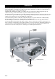
English Connecting external components to this unit Connect external component such as a TV or DVD player to this unit. Connect your TV or DVD player to this unit using appropriate cables as shown below. Connecting a subwoofer enhances bass sound for listening enjoyment. For further information on connecting other components, see pages 15 to 22 in the Owner’s Manual. YSP-1100 QUICK REFERENCE GUIDE DVD player Cables used for connections Connect cables in the following order.
Continued from the front Carry out the AUTO SETUP (IntelliBeam) procedure to adjust the settings that best match your listening environment. Enjoying surround sound This unit employs the YAMAHA IntelliBeam technology with the aid of the supplied optimizer microphone, allowing you to achieve highly accurate sound adjustments that best match your listening environment. Be advised that it is normal for loud test tones to be output during the AUTO SETUP procedure.