Model High -TechⅣ Ⅳ Programmable Controller Operating Instructions Version 2 Yamato Scientific Co.
1. INTRODUCTION ................................................................ .................................................................................. .................................................. 2 Explanation of Character on the display................................ display ................................................................ ................................................................. ................................. 3 2. INPUTTING, EDITION AND DELETING PROGRAMS ...
Cautions on the backup battery Charge the backup battery for memorizing program built-in the unit when you use the unit for the first time., and also do that when you have not used the unit for 3 weeks and more. To turn off the circuit breaker without charging may delete the programmed data Once turned on the circuit breaker, the battery can be charged. It takes about 48 hours to charge the battery completely when discharged.
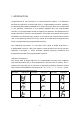
1. INTRODUCTION Congratulations on your purchase of a Yamato Scientific's product. 'I his document discusses the operation of Model High-Tech IV Programmable Controller, especially the inputting and presetting methods of its various functions, which are not described in the operating instructions of the systems equipped with the programmable controller.
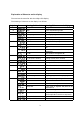
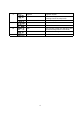
Explanation of Character on the display The oven has the controller with the 4-digit LED display. The meaning of Character on the display is as follows: Capital A Character Meaning of Abbreviation accumulation Meaning of Character on the display Integrated time B beep Alarm sound setting mode C clock delete program Setting of the date and the hour Deleting a program door display The open door Sub display switching mode end Setting mode for program end error ## Error code ## fan fan f.
S ## ## T W ## Y segment Segment number soak time step Soak time of Segment ## (Holding time of the ramp level) Not in Ramp Operation temp Temperature mode time Time mode wait wait ## Wait function (Keep the operation until the desired temperature is achieved) Wait function of Segment ## year the Christian era 4
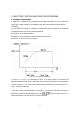
2. INPUTTING, EDITION AND DELETING PROGRAMS 2.1 Program Composition A program is a combination of segments and repeat commands, in which ramp time, ramp level, repeat frequency, end segment and other parameters should be preset. [Segment] Fig 2.1 shows the concept of a segment. Temperature and time patterns of a segment are determined by the 3 basic parameters below. Ramp level : Desired temperature Ramp time : Time required to achieve the preset ramp level Soak time : Time to hold the ramp level Fig. 2.
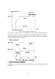
Fig. 2.2: Step Variation of Ramp Time The soak time is set at zero (0) for a segment with only gradient-operation, while the ramp time is set at zero (0) for a segment with only fixed-value operation. Figure 2.3 shows a connected pattern of these 2 segments. In this figure, Section (4) is a segment only with the soak time set at zero (0). Fig. 2.3: Connection of Segmen4 ■ Attribute Parameters of Segments In addition to the three basic parameters discussed above, you may preset the following parameters.
Wait Function ON/OFF: This function temporarily suspends counting time of the program operation when influence of loads in the chamber or external disturbance such as door operation has the chamber temperature failed in achieving the preset desired temperature until the chamber temperature reaches the preset value. You may either turn ON or OFF the function.
Fan Revolution Revolution: You may preset the revolution of the internal agitation fan in the range from 1 (low speed) to 10 (high speed). See the operating instructions of your system for the fan revolution (rpm), which varies with systems. If your system cannot control the fan revolution, the programmable controller automatically skips this function. If your system is equipped with optional automatic damper controller, you may preset the damper aperture at 5 different levels.
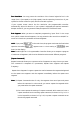
Fig.2.4.1:Nesting of a Repeat Command Fig.2.4.2:Cross Setting of Repeat Commands Repeat frequency :You may preset Repeat Frequency in the range from 1 to 9999 times. If you set the repeat frequency at zero(0),which means endless repetition of the segments ,the program continues repeat operation until it is forced to stop.
Indication of the rest of the repeat count The rest of the repeat frequency including the ongoing segment can be shown on the sub display by using the DISPLAY key while performing the repeat command of the program operation. [Operation Procedure] Key Operation Main Display Sub Display Explanation The repeat operation is on : Ex. While performing the repeat operation the segment 2 to 3 of the program 2 Push the Display It shows the present key several times measured temperature (Ex.
2.2 Inputting Programs In this paragraph , you will learn how to input the program shown in Fig.2.5 as an example into Program No.2. Fig.2.
Note: In the tables below, hollow alphanumeric characters mean that they are flashing on the corresponding display. [Setting Program Number] Key Main Sub Operation Display Display Push the e.g., Explanation Left 2 digits: Number of the existing MODE key programs and Right 2 digits Remaining memory size (%) then push either ▲ key or ▼ key Push ENTER e.g., e.g., key, Activates Program input & Edit mode. Main: Indicates Program No. 1. Left 2 digits: Memory size of Program No.
Push ▲ or ▼ Push ▲ or ▼ key to show a desired key and ENTER temperature of 150_C and push ENTER ↓ key. key to accept it as Ramp Level 1. The main display changes from flashing to (Lighting) Push ▲ or lighting, Approx. l second later Requesting to input Soak Time 1 e.g., Segment 1. of ▼ Push ▲or▼ s key to show a desired key and ENTER soak time of 1 hour 20 minutes and key. push ENTER key to accept it as Soak Time 1. The main display changes from (Lighting) flashing to lighting.
[SettingSegment2] Key Operation Push ENTER Main Sub Explanation Display Display Approx. 1 second later Activates Input mode for Segment 2. key, Left 2 digits. Program number you are ↓ working on. ↓ Right 2 digits: Remaining memory size Requesting to input Ramp Time 2 of Segment 2. Input and preset the following parameters for this example in the same manner as Segment 1.
[Setting a Repeat Command] hey Main Sub Display Operation Display Approx. 1 second later Push ▲ or ▼ key. ↓ Push ENTER key. ↓ Explanation The main display shows that the programmable controller is ready for inputting Segment 4. Push▲ or ▼ key to change the controller to the input mode of Repeat Command. The main display flashes (Repeat). Requesting to input the number of Repeat Push ▲ or ▼ key and ENTER key. Push▲ or ▼ key and ENTER key. Start Segment .
[Inputting and Setting End Segment] Key Main Sub Explanation Operation Display Display Push ENTER key. Activates Input mode for Segment 5. ↓ ↓ Requesting to input Ramp Time5 ( Push ▲ or ▼ key ↓ ) of Segment 5. Push ▲ or ▼ key to change to Program Input mode for End Segment. Push ENTER Requesting to turn on or off the fan or input key its revolution level. Push ▲ or ▼ Push A or t key to change the setting. In key. this example, turn off the fan. Push ENTER Approx.
2.3 Editing Programs Model High-Tech IV Programmable Controller supports Edit function of only ・Segment parameters; and ・Repeat parameters or editing programs. Take note that the programmable controller does not support Delete of repeat command and Insert of new segments or a new repeat command. In this paragraph, you will edit Segment 3 of Program No. 2 in Fig. 2.6, which is composed of the following segments and a repeat command.
Push ENTER Indicates that the ramp time of Segment S key. is set at the step operation. Change it to the gradient operation with a ramp time of 45 minutes. Input and preset the following parameters in the same manner as discussed in "inputting Programs." : 45 minutes : 150℃ : o minutes (This is a segment of only the gradient operation.) : ON : 10 You have changed the parameters with asterisks. For the other parameters you do not change, push only ENTER key.
2.4 Deleting Programs You can delete the programs not in use any longer from the programmable controller. Take note that on Program Delete mode, you cannot check the contents of the program you are going to delete. In this paragraph, you v ill learn how to delete Program No. 1 Key Main Sub Operation Display Display Push the Explanation Push MODE key several times to flash MODE key and (Delete Program) on the man then display.
Temporary Suspension of Program Operation Temporary suspension of program operation means to stop the program timer and temporarily keep the programmable controller at the status of ready-for-operation. During the suspension, the programmable controller shuts off power supply to heaters and does not regulate chamber temperature.
3. INPUTTNG AND SETTING FUNCTIONS You can add a variety of functions by using MODE key. This section discusses the inputting and setting functions, which are common to all Yamato Scientific's machinery and equipment. For setting the functions particular to your system, see the operating instructions of the system. If your system does not support certain functions, pushing MODE key simply skips those functions, which are not shown on the displays. 3.
Accepts the change of the setting from time Push to period of operation. ENTER (Lighting) key. Approx. 1 second later The displays return to their initial indications shown immediately before you pushed MODE key. Note: Time is default setting. When you are setting the operation parameters, you cannot switch this setting.
3.2 Setting and Releasing Panel Key Lock Panel Key Lock deactivates the eight keys on the control panel, except for indication Switching key. With this special function, you can prevent accidental or unauthorized key operation ashen the programmable controller is in service. [Setting Panel Key Lock] Key Main Sub Operation Display Display Push the MODE key and then push either ▲ key or▼ key Push ENTER (Lighting) key. Approx. 1 second later Push ▲ or ▼ key.
3.3 Turning ON and OFF Buzzer Sound If something abnormal happens on your system, all the indicator lamps including alarm indicator lamps start flashing, the main display shows the present chamber temperature and the sub display shows the error code of the abnormal condition. You can choose to activate or deactivate buzzer sound when your system is in trouble. In this paragraph, you will learn how to turn on the buzzer sound. [Procedure] Main Sub Key Display Display Operation Push the MODE key e.g.
3.4 Indication of Integrating Operation Time This function accumulates the operation time when Power key is turned on. Maximum accumulation of time is 49,999 hours, which cannot be reset. Accumulated operation time provides useful information when you determine the timing of maintenance. In this paragraph, you will learn how to show the accumulated operation time.
3.5 Setting Date and Time The timer clock built in Model High-Tech IV Programmable Controller has been calibrated at the standard time in our factory. However, you still need to adjust it periodically to make sure of its correct time indication in your operating environment. In this paragraph, you will learn how to calibrate the built-in timer clock. Note: The built-in timer clock causes an daily error of 12 seconds at a working temperature of 25℃.
3.6 Hold Function Hold function is the one of functions that the HitecⅣcontroller supports by using the MODE key. It can work only if the setting time of the operation start time of the Auto-Start operation and the Program operation and the operation stop time are not set in hours but in a period of time. General Description of the Hold Function Once the Hold Function is on, immediately the HitecⅣcontroller stops the built-in timer and keeps the condition. The definite examples are shown below. 1.
Operating procedure Key Operation Push key push or ▼ Main Display Sub Display the MODE and then either▲key key Explanation Blink display. (Hold) on the main The sub display shows the present setting. Activates mode. Push the ENTER key Hold Function Setting :Hold function is off (inactive) :Hold function is on (activate) Approx.
3.7 Communication lock out function This function makes the communication between the PC and HitecⅣcontroller enable / disable. If this function is activated during communicating with a host computer, the controller closes the communication Operating Procedure Key Operation Main Display Sub Display Explanation Push the MODE key and then push either ▲ key or ▼ key Blink (Communication Lockout) on the main display.
Releasing the Communication Lock-out By pushing the MODE key while the Communication Lock-out function is on, Hitec Ⅳcontroller goes to the setting and releasing the Communication Lock-out mode, and then you can release the Communication Lock-out condition to choose ‘off’ by pushing the ▲key or the ▼ key. ✻Precaution in handling✻ handling✻ ※ The remote operation cannot be performed while the Communication Lock-out function is on.
4. SAFETY MEASURES AND PRECAUTIONS This section discusses the safety measures provided for Model High-Tech IV Programmable Controller, and the operational precautions of the controller and your system regulated by the controller. See the operating instructions of your system, which also describe safety measures and precautions. 4.
5. Behavior after Power Restoration When having a blackout during operation, the controller resumes the following operations after the power restoration. 5.1 When having a blackout during the program operation The controller automatically resume the program operation where it left at the power shutdown.