Low Temperature Incubator Model IJ 201/300/300W Instruction Manual - Second Edition - z Thank you for purchasing "Low Temperature Incubator, IJ Series" of Yamato Scientific Co., Ltd. z To use this unit properly, read this "Instruction Manual" thoroughly before using this unit. Keep this instruction manual around this unit for referring at anytime. WARNING!: Carefully read and thoroughly understand the important warning items described in this manual before using this unit. Yamato Scientific Co. LTD.
Contents Cautions in Using with Safety................................................................ 1 • • • Before Using this unit ............................................................................. 4 • • Requirements for Installation......................................................................................... 4 Change the Direction of Opening/Closing Door (only for IJ300/300W)......................... 8 Description and Function of Each Part .............................
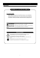
Cautions in Using with Safety Explanation MEANING OF ILLUSTRATED SYMBOLS Illustrated Symbols Various symbols are used in this safety manual in order to use the unit without danger of injury and damage of the unit. A list of problems caused by ignoring the warnings and improper handling is divided as shown below.Be sure that you understand the warnings and cautions in this manual before operating the unit.
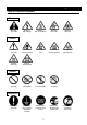
Cautions in Using with Safety Table of Illustrated Symbols Warning Warning, generally Warning, high voltage Warning, high temperature Warning, drive train Warning, explosive Caution, generally Caution, electrical shock Caution, scald Caution, no road heating Caution, not to drench Caution, water only Caution, deadly poison Prohibit, inflammable Prohibit, to disassemble Prohibit, to touch Compulsion, connect to the grounding terminal Compulsion, install on a flat surface Compulsion, discon
Cautions in Using with Safety Fundamental Matters of "WARNING!" and "CAUTION!" WARNING! Do not use this unit in an area where there is flammable or explosive gas Never use this unit in an area where there is flammable or explosive gas. This unit is not explosion-proof. An arc may be generated when the power switch is turned on or off, and fire/explosion may result. (Refer to page 45 "List of Dangerous Substances".
Before Using this unit Requirements for Installation WARNING! 1. Always ground this unit • Be sure to connect the earth wire (the green cable of power cord) to the grounding conductor or ground terminal to prevent accidents caused by electric leakage. • Do not connect the earth wire to gas or water pipes. If not, fire disaster may be caused. • Do not connect the earth wire to the ground for telephone wire or lightning conductor. If not, fire disaster or electric shock may be caused.
Before Using this unit Requirements for Installation 3. Do not use this unit in an area where there is flammable or explosive gas (Refer to page 45 "List of Dangerous Substances".) • Never use this unit in an area where there is flammable or explosive gas. This unit is not explosion-proof. An arc may be generated when the power switch is turned ON or OFF, and fire/explosion may result. 4. Do not modify 5. Installation on horizontal surface • Modification of this unit is strictly prohibited.
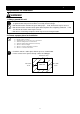
Before Using this unit Requirements for Installation CAUTION! 6. Do not make an overload 7. Do not set samples in close formation • The withstand load of shelf is 10kg (uniform load)Set the samples apart each other. • The temperature in furnace cannot be controlled if too much samples are set there. Make sure to use the shelf and set samples apart each other so as to make the free space of 30% or more to the furnace to acquire accuracy of temperature.
Before Using this unit Requirements for Installation 11. Drain of dew drops • Use the attached tray for drain of dew drops. They may occur inside the furnace or around the door packing depending on environmental condition or samples used when the cooling device is operated. 12. Handling of power code • Do not entangle the power cord. This will cause overheating and possibly a fire. • Do not bend or twist the power cord, or apply excessive tension to it. This may cause a fire and electrical shock.
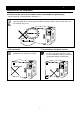
Before Using this unit Change the Direction of Opening/Closing Door (only for IJ300/300W) IJ300/300W can be changed the direction of opening/closing the door easily. The door opened/closed to the right or left can be selected according to the place where it is installed and the convenience of operation. The direction of opening/closing the door is set to left at the shipping from factory.
Description and Function of Each Part Main Unit IJ201 Air intake Front view Control panel Y yamato Door IJ201 Exhaust Door handle Power switch (Earth leakage breaker) Plate for drainage Air intake Rear view Air intake filter Production plate Power cord Air intake filter (on the base of the unit) 9
Description and Function of Each Part Main Unit IJ300/300W Front view Air intake filter Door (IJ300W: With an observation window) Low tem p incubator IJ3 00 Power switch (Earth leakage breaker) Control panel Door packing Shelf Plate for drainage Rear view Production plate Air intake filter Power cord 10
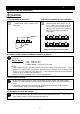
Description and Function of Each Part Control Panel ⑲ ⑧ ⑭ ⑨ ⑩ ⑪ ⑫ ⑬ POWER ⑮ ⑯ ③ ⑰ ① ⑱ ② ④ ⑦ ⑤ ⑥ ① START/STOP Key: Starts/stops the operation. ② ▲▼ Key: Uses for rising UP/lowering DOWN the setting value. ③ ENTER Key: Settles the inputted value. ④ FIXED TEMP Key: Chooses the fixed temperature operation. ⑤ TIMER Key: Chooses the timer operation (Quick Auto Stop/Auto Stop/Auto Start). ⑥ PROGRAM Key: Chooses the program operation or program creation mode.
Description and Function of Each Part Characters of the Controller The characters VS4 controller shows are as follows: Character Identifier Name Purpose Used for starting the fixed temperature operation. FiX Fixed Temperature Setting Mode Sv Temperature Setting Used for setting the temperature. AStP Timer Setting Mode Display Represents the setting of quick auto stop or auto stop operation. AStr Timer Setting Mode Display Represents the setting of auto start operation.
Operation Method Operation Mode and Function List All the operation mode of this unit is as follows; No. Name 1. 2. 3. 4. 5. Description Page Fixed Temperature Operation Pressing the FIXED TEMP key enters into the fixed temperature operation setting mode. Pressing it again enters into the temperature setting mode. The "▲▼" are used to set temperature. Pressing the START/STOP key starts or stops operation.
Operation Method Operation Mode and Function List The operation function of this unit is as follows; No. Name 1. Overheating prevention function Description Auto overheating prevention function This function is set to be automatically activated (auto reset) when the temperature exceeds the setting temperature by 6℃.
Operation Method Operation Mode, Function Setting Key, and Characters The operation mode setting and function setting use the key operation and characters show in the following figure.
Operation Method Setting of Overheating Prevention Device The unit has the overheating prevention device (manual reset) that consists of independent temperature measurement circuit, CPU, sensor and output circuit (it shares power source, display, and key input with the controller) in addition to the automatic overheating prevention function (auto reset) in the controller. Setting range/function The unit has failsafe functions against overheating.
Operation Method Fixed Temperature Operation 1. Turn on the power (turn on the breaker in front) Fixed temperature operation procedure The default value is displayed for about four seconds after turning on the power. The screen then displays the initial setting. The current temperature in furnace, operation mode character and setting temperature of overheating prevention device are displayed on respective screens. Measurement temperature screen: Displays the current temperature in furnace.
Operation Method Quick Auto Stop Operation Quick auto stop operation procedure This operation is used to specify the period up to automatic stop, i.e., sets the auto stop timer during operation. 1. Set the time up to stop during fixed temperature operation • Check that the FIXED TEMP lamp lights on and that the unit is under operation. • Press the TIMER key. • The measurement temperature display screen displays the character "tim", which indicates the timer setting.
Operation Method Auto Stop Operation Auto stop operation procedure This operation is used to specify the automatic stop time in the fixed temperature operation. 1. Set stop time ① Press the TIMER key on the initial screen. Press the TIMER key again. The setting temperature display screen displays the character "AstP", which indicates the auto stop operation, with blinking. ② Press the ENTER key. The measurement temperature screen displays the character "SV", which indicates the temperature setting.
Operation Method Auto Stop Operation 3. Stop/terminate timer operation • The operation stops automatically at setting time. • Buzzer continues to sound for about five minutes at operation stop. • The setting temperature screen displays the character "End", which indicates termination of operation, with the FIXED TEMP and AUTO STOP lamps lighting on. Press the START/STOP key to terminate the timer operation mode. The screen returns to the initial setting screen.
Operation Method Auto Start Operation Auto start operation procedure This operation is used to specify the period up to automatic start after power on. 1. Set start time ① Press the TIMER key on the initial screen. Press the TIMER key again. The setting temperature display screen displays the character "Astr", which indicates the auto start operation, with blinking. ② Press the ENTER key. The measurement temperature screen displays the character "SV", which indicates the temperature setting.
Operation Method Auto Start Operation 3. Stop/terminate timer operation • The operation starts automatically at setting time. • Press the START/STOP key for one second to stop or terminate operation. The screen returns to the initial setting screen. To correct or check setting… Changing the setting temperature or time during operation is possible by pressing the TIMER key. Use the "▼▲" to change the setting value. Press the ENTER key respectively after changing the setting.
Operation Method Program Operation This operation is used to change the temperature according to the setting temperature and time. Temp. △ Start △ Stop Time Program types Six patterns of program types maximum can be input. PrG1 1 program pattern using 30 steps maximum can be created. PAt1 PrG2 2 program patterns using 15 steps maximum can be created. PAt2 PAt1 PrG3 3 program patterns using 10 steps maximum can be created.
Operation Method Program Operation Program creation The program pattern below is explained as an example. 1. Program pattern example Temp. 40℃ 30℃ 20℃ 10℃ 0℃ Step 1 2 3 4 5 6 7 Temp.(℃) 40 40 35 35 25 25 15 Time(min.) 40 30 15 30 10 30 30 POWER ← Repeat function → The number of steps is not counted. 8 9 10 10 15 30 1. Turn on the power • Turn on the power switch of the unit. • The display on the controller lights on.
Operation Method Program Operation The example shown below explains the method of program registration using PrG3. 4. Register program ① Select PrG3 referring to 3 mentioned above.. ② Input the number of steps, temperature and time for respective steps using the program creation sheet. ③ Press the ENTER key. The PAt1 is displayed with blinking. ④ Select the unused pattern from among Pat1, Pat2 and Pat3 using the "▲ ▼". ⑤ Press the ENTER key.
Operation Method Program Operation 5. Start program operation • Press the START/STOP key for about one second. The program operation previously set starts. • The PROGRAM lamp lights on and the setting temperature screen displays the step currently under operation. Press the "▼" to check the setting temperature and residual time of step currently under operation on the setting temperature screen. 6. End program operation • Buzzer continues to sound for about five minutes at operation stop.
Operation Method Program Operation Use program repeat function This section explains how to register the program repeat (repeating a program pattern) in program operation. This section explains the registration procedure of program using repeat function in "4. Register program" above.
Operation Method Program Operation Programming Preparation Form 1 (Please use this form by making copies) Register with: PrG1 PrG2 PrG3 PAt1 PAt2 PAt3 No.
Operation Method Program Operation Programming Preparation Form 2 (Please use this form by making copies) Register with: PrG1 PrG2 PrG3 PAt1 PAt2 PAt3 No. Date Project Name Programmer Input Value Temperature (℃) Time (min.
Operation Method Other Functions Use calibration offset function Calibration offset is a function which corrects the difference between the temperature in furnace and that of controller (sensor temperature) if arises. The function parallel corrects the difference either to the plus or minus side within the whole temperature range of unit. The function can be set or cancelled by the SUBMENU key. Corrected temp. to plus side Current temperature Corrected temp.
Operation Method Other Functions Use Shaker Small shaker(s), such as shaker MK140 type, can be installed in IJ300W type. the cable for taking out the observation window for checking a shake state, and the service wall socket for shaker and the power cord of shaker -- the hole is equipped standardly Moreover, if an optional shaker installation stand with a slide rail is used, it can pull out the whole shaker and receipts and payments of a sample can be performed comfortably.
Handling Precautions WARNING! If a problem occurs If smoke or strange odor should come out of this unit for some reason, turn off the power key right away, and then turn off the circuit breaker and the main power. Immediately contact a service technician for inspection. If this procedure is not followed, fire or electrical shock may result. Never perform repair work yourself, since it is dangerous and not recommended.
Handling Precautions Do not use corrosive sample Stainless steel SUS304 is used for interior; however, it may be corroded by strong acid etc. And the door packing made of silicon rubber may be corroded by some kind of solvent, e.g. alkaline, oil, halogen etc. Do not use the sample includes those. Use under proper temperature range Operational temperature range of this unit is 0 to 60℃. Never set the temperature out of that.
Maintenance Method Daily Inspection and Maintenance For the safety use of this unit, please perform the daily inspection and maintenance without fail. Using the city water to this unit might attach dirt. Do inspect and maintain this point while performing daily inspection and maintenance. WARNING! • • • Disconnect the power cable from the power source when doing an inspection or maintenance unless needed.
Maintenance Method Daily Inspection and Maintenance Cleaning of radiating fin Unplug the power plug at cleaning • Clogging on the fin degrades the performance of the unit. It may also cause the failure of unit. • The degree of clogging on the fin varies depending on the surrounding environment or used hours. Clean it regularly as necessary. ① Loosen the two fixing screws on the ceiling board of unit and remove the board. For the IJ201 type, remove the side board.
Setting of Air Jacket (Optional accessory) 1. Set the shelf at the lowest stage in a way that the side with margin may come innermost. 2. Set this on the shelf of the air jacket, and push it in. 3. Pus the air jacket inward until it hits the depth. Enter this while adjusting it closely to the edge of the furnace.
Long storage and disposal When not using this unit for long term / When disposing CAUTION! When not using this unit for long term… • Turn off the power and disconnect the power cord. WARNING! When disposing… • Keep out of reach of children. • Remove the door and driving parts. • Treat as large trash. Environmental protection should be considered We request you to disassemble this unit as possible and recycle the reusable parts considering to the environmental protection.
In the Event of Failure… Safety Device and Error Code This unit has an automatic diagnosis function built in the controller and safety devices independent of the controller. The table below shows the cause and the solution method when the safety device operates. Error Code: When an abnormal condition occurs, an error code appears and the alarm lamp lights in the controller, the buzzer sounds simultaneously. Record the error code and turn off the power of device immediately.
In the Event of Failure… Trouble Shooting Before call us... Condition The device does not start when turning on the power switch. Dew condenses Temperature fluctuates during the operation. Possible Causes • Power plug is not connected to the receptacle correctly. • Power failure. • Humidity is too high. • Samples are too moist. • Too much samples. • Atmospheric temperature is too high or low. • The change of ambient temperature is remarkable. • Samples are too moist.
After Service and Warranty In Case of Request for Repair If the failure occurs, stop the operation, turn OFF the power switch, and unplug the power plug. Please contact the sales agency that this unit was purchased, or the Yamato Scientific's sales office. < Check following items before contact > ◆ Model Name of Product See the production plate attached to this unit.
Specification Model Temperature control range Temperature adjustment accuracy Temperature distribution accuracy Temperature rise time IJ201 IJ300 0 to 60℃ (Ambient temp.: 20℃, No load) ±0.5℃ (Set temp.: 37℃) ±1.0℃ (Set temp.: 37℃) Approx. 50min.
Wiring Diagram IJ201 ELB P1 AC100V X1 2 1 1 2 2 NFE 3 4 3 H 4 2 X2 X2 + SPS-2 + - + SPS-1 + - X1 Symbol ELB P1, P2 X1, X2 SSR CT NF F1, F2 F2 18 1 SSR 3 4 1 1 CN9 2 CN2 18 3 18 1 2 3 CN4 4 5 6 CN1 CN8 CN2 1 PIO A 1 B TB1 2 b 3 1 TB2 2 + - TH1 TH2 CONT + F1 18 1 CN1 2 CT P2 1 1 1 2 CN5 3 1 C1 Part name Earth leakage breaker Terminal block Relay Breakerless relay Current transformer Noise filter Fan C2 Symbol H C1, C2 CONT PIO TH1, TH2 SPS-1 SPS-2 42 Part name He
Wiring Diagram IJ300/300W T ELB P1 1 AC100V 1 1 2 CN5 CN8 3 18 2 1 2 X1 NFE 3 4 3 H P2 1 1 2 CT 4 2 X2 + SPS-1 + X1 + F1 F2 C4 C3 + CN2 18 1 3 1 2 3 CN4 4 5 6 1 TB2 2 A B b + - TH1 TH2 CONT C2 1 PIO TB1 2 + SPS-2 + - CN1 18 1 1 CN9 2 CN2 18 3 1 CN1 2 X2 + SPS-2 + - SSR 3 4 1 C1 T: Only for IJ300 W, a socket is.
Replacement Parts Table IJ201 Part Name W sensor VS4 PLANAR board VS4 display circuit board Tough card Main relay SSR Power cord kit Earth leakage breaker Noise filter CT Specification NL-201RB-J0001 Pt100/K VS4 VS4 50mm AJR3714 TRS5225 1.25sq 3p plug 1.8m FG32R/10-30MA 10A ZAG2210-11S 10A CTL-6-S-H Manufacturer Yamato Scientific Yamato Scientific Yamato Scientific Yamato Scientific Matsushita Toho Denshi Yamato Scientific Fuji Denki TDK URD Code No.
Reference List of Dangerous Substances Never use explosive substances, flammable substances and substances that include explosive or flammable ingredients in this unit.
Responsibility Please follow the instructions in this document when using this unit. Yamato Scientific has no responsibility for the accidents or breakdown of device if it is used with a failure to comply. Never conduct what this document forbids. Unexpected accidents or breakdown may result in. Note ◆ The contents of this document may be changed in future without notice. ◆ Any books with missing pages or disorderly binding may be replaced.