Constant Temperature Drying Oven Model DVS402 DVS602 First edition ● Thank you very much for purchasing this Yamato DVS series constant temperature drying oven. ● Please read the “Operating Instructions” and “Warranty” before operating this unit to assure proper operation. After reading these documents, be sure to store them securely together with the “Warranty” at a handy place for future reference.
Table of contents 1. Safety precautions ........................................................................................................................1 Explanation of pictograms ...............................................................................................................1 List of symbols.................................................................................................................................2 Warning・Cautions ................................................
1. Safety precautions Explanation of pictograms About pictograms A variety of pictograms are indicated in this operating instruction and on products to assure safe operation. Possible results from improper operation ignoring them are classified as follows. Be sure to fully understand the descriptions below before proceeding to the text.
1.
1. Safety precautions Warning・Cautions Warning Never operate the unit in an atmosphere containing flammable or explosive gas Never operate the unit in an atmosphere containing flammable or explosive gas. Otherwise, an explosion or a fire may result since the unit is not explosion-proof. See section “13. List of dangerous materials” on page 43. Be sure to connect the ground wire. Be sure to connect the ground wire correctly. an electrical shock or a fire.
2. Before operating the unit Precautions when installing the unit Warning 1. Be sure to connect the ground wire. ・ Power supply for this product is 100V AC. ・ Be sure to connect the ground wire (green core wire of the power cord) to the ground wire or the ground terminal in order to prevent an electrical shock from electric leakage. ・ Never connect the ground wire to gas or water pipes. Otherwise, a fire may result. ・ Never connect the ground wire to the ground for telephone wire or lightning conductor.
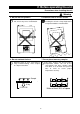
2. Before operating the unit Precautions when installing the unit Warning 3. Never operate the unit in an atmosphere containing explosive or flammable gas Never operate the unit in an atmosphere containing flammable or explosive gas. Since the unit is not explosion-proof, an arc is discharged when turning a switch “ON” and “OFF” and during operation and a fire or an explosion may result. See the section “13. List of dangerous materials” on page 43 for flammable and explosive gases.
2. Before operating the unit Precautions when installing the unit Warning 4. Do not alter the product. 5. Install the unit on a level surface The user shall never attempt to alter the unit since it may cause a malfunction. Flat Install the unit on a level surface. Installing this unit on a slope might cause unexpected troubles or malfunctions. Alteration 6. Do not overload shelves. 7. Do not place too many samples. Too many samples may prevent proper temperature control.
2. Before operating the unit Precautions when installing the unit Caution 8. Be sure to connect the power plug to the dedicated wall outlet. Use a power distribution panel or a wall outlet that meets the electrical capacity of the unit. DVS402 AC100V 12.
2. Before operating the unit Precautions when installing the unit Caution 11. About handling of the power cord Never use electrical power cords bundled. When these are used bundled, they might overheat causing a fire. Do not convert, forcibly bend, twist or pull the power cord. Otherwise, a fire or an electrical shock may result. Do not place the power cord under a desk or a chair, or sand between objects to avoid it from being damaged.
3.
3. Names and functions of parts Operation panel ⑧ ⑨ ⑩ ⑪ ⑭ MEASURED TEMP. HEATER ALARM ℃ AUTO STOP AUTO START SET TEMP. ⑮ FIXED TEMP. OVER TEMP. PROTECTOR PROGRAM ⑫ ⑯ ⑬ ② FIXED TEMP. ① RUN ENTER ③ STOP TIMER PROGRAM SUB MENU ⑦ ④ ⑤ No. ⑥ ① Name RUN/STOP key Operation/action Used for starting/stopping operation ② ▲▼ keys Used for selecting settings. ③ ENTER key Used for determining a selected setting. ④ FIXED TEMP. key Key for selecting fixed temperature operation.
3. Names and functions of parts Explanation of characters Characters on the VS4 type controller are explained in this section. Characters Identifier Name Application Fix Fixed temperature operation setting Means settings for fixed temperature operation. Sv Temperature setting Used for setting a temperature. AStP Auto stop setting Used for setting auto stop operation. AStr Auto start setting Used for setting auto start operation. tim Time setting Used for setting a time.
3. Names and functions of parts Explanation of characters Characters Identifier Name Application cAL Calibration offset setting Used for inputting a calibration offset temperature See section “Using the calibration offset function” on page 31. oH Setting overheat protection device temperature Used for setting an overheat protection device temperature. See section “Settings for overheat prevention device” on page 16.
4. Operating procedures List of operation modes and functions Operation modes of the unit are as shown below: № 1 2 3 4 5 Name Description Page Fixed temperature operation Pressing the FIXED TEMP. key to enter the fixed temperature operation setting mode. Pressing the FIXED TEMP. key again to enter the temperature setting mode. Set a temperature with the ▼▲ keys. Pressing the RUN/STOP key to start operation, and pressing the RUN/STOP key again to stop operation. P.
4. Operating procedures List of operation modes and functions Operating functions of the unit are as shown below: № Description Page Overheat prevention function Automatic overheat prevention function: This function is linked to the unit set temperature and has been set to so that it is automatically activated (returned automatically) at a temperature 12℃ higher than the set temperature in the bath.
4. Operating procedures Operation mode・function setting keys and characters Key operations and characters in the diagram below are used for operation mode and function settings. ELB ON FIXED TEMP TIMER PROGRAM Fixed temp. operation Timer operation Programming FIXED TEMP. TIMER PROGRAM SUB MENU SUB MENU ▼ ▲ ▼ ▲ Setting overheat prevention device Calibration offset function Press to switch Program mode setting oH cAL ENTER ENTER Setting overheat prevention device temp.
4. Operating procedures Settings for overheat prevention device The safety device for preventing overheat has the automatic overheat prevention function for the controller (automatic recovery) and has the power supply, the display and the key input assembly in common with the controller as well as it has an overheat prevention device (manual recovery) as a secondary safety measures that consists of separate temperature measurement circuit, the CPU, the sensor and the output circuit.
4. Operating procedures Operating procedures (fixed temperature operation) How to start fixed temperature operation 1. Turn power ON. (Turn the ELB to ON.) When power is turned ON, the initial values will be displayed for about four seconds, then the initial screen will appear and the current bath temperature, operation mode character and the overheat prevention set temperature are displayed on each of the displays. MEASURED TEMP. HEATER ℃ ALARM AUTO STOP AUTO START SET TEMP. FIXED TEMP.
4. Operating procedures Operating procedures (quick auto stop operation) Procedures for quick auto stop operation MEASURED TEMP. HEATER ALARM ℃ AUTO STOP AUTO START SET TEMP. FIXED TEMP. OVER TEMP. PROTECTOR PROGRAM RUN ENTER FIXED TEMP. Used when you want to, for example, “stop fixed temperature operation being performed automatically in several hours. Quick auto stop operation is a function to enable auto stop timer setting during operation. 1.
4. Operating procedures Operating procedures (auto stop operation) Procedures for auto Used when you want to “set automatic stop after set time has elapsed from the start of the fixed temperature operation.” stop operation MEASURED TEMP. HEATER ALARM ℃ AUTO STOP AUTO START SET TEMP. FIXED TEMP. OVER TEMP. PROTECTOR PROGRAM RUN ENTER FIXED TEMP. STOP TIMER PROGRAM 1. Setting a stop time ① Press the TIMER key in the initial screen.
4. Operating procedures Operating procedures (auto stop operation) MEASURED TEMP. HEATER ALARM ℃ AUTO STOP AUTO START SET TEMP. FIXED TEMP. OVER TEMP. PROTECTOR PROGRAM RUN ENTER FIXED TEMP. STOP TIMER PROGRAM SUB MENU When you want to correct set temperature or set time, or confirm settings 3. Stopping and ending timer operation Operation stops automatically when the set time comes. The buzzer sounds for about five seconds to indicate operation has that indicates stopped.
4. Operating procedures Operating procedures (auto start operation) Procedures for auto start operation MEASURED TEMP. HEATER ALARM ℃ AUTO STOP AUTO START SET TEMP. FIXED TEMP. OVER TEMP. PROTECTOR PROGRAM RUN ENTER FIXED TEMP. STOP TIMER PROGRAM Used when you want to “start operation automatically after the set time.” 1. Setting an operation start time ① Press the TIMER key in the initial screen. ② The timer mode you used in the previous session is displayed on the SET TEMP. display.
4. Operating procedures Operating procedures (auto start operation) MEASURED TEMP. HEATER ALARM ℃ AUTO STOP AUTO START SET TEMP. FIXED TEMP. OVER TEMP. PROTECTOR PROGRAM RUN ENTER FIXED TEMP. 3. Stopping and ending timer operation Operation starts automatically when the set time comes. Press the RUN/STOP key for about one second to start or stop operation. The screen switches to the initial setting screen.
4. Operating procedures Preparing a program Used when you want to “operation at an increased or decreased temperature according to specific time.” Program operation Temp. △Program operation start Preparing type △Operation end Time Up to six patterns of programs can be stored and input. PrG1 ― One pattern of a program consisting of up to 30 steps can be made. PAt1 Two patterns of a program consisting of up to 15 steps can be made.
4. Operating procedures Preparing a program Rough heating and cooling times of the DVS model are as follows: Figures show required time for each of temperature zones. [It requires about 15 minutes to raise temperature from 100℃ to 150℃.] However, be sure to conduct trial operation to determine a correct time since time required for stabilizing temperature needs to be added after the specific set temperature is reached.
4. Operating procedures Preparing a program ② Select a program mode you want and press the ENTER key. MEASURED TEMP. HEATER ALARM ℃ AUTO STOP AUTO START SET TEMP. FIXED TEMP. OVER TEMP. PROTECTOR PROGRAM RUN ENTER FIXED TEMP. STOP TIMER PROGRAM SUB MENU ・When PrG1 is selected, End appears on the MEASURED TEMP. display and the number of steps registered flashes on the SET TEMP. display. is selected, PAt appears on the ・When PrG2 MEASURED TEMP.
4. Operating procedures Preparing a program MEASURED TEMP. HEATER ALARM ℃ AUTO STOP AUTO START SET TEMP. FIXED TEMP. OVER TEMP. PROTECTOR PROGRAM RUN ENTER FIXED TEMP. STOP TIMER PROGRAM SUB MENU Request for operation check MEASURED TEMP. HEATER ALARM ℃ AUTO STOP AUTO START SET TEMP. FIXED TEMP. OVER TEMP. PROTECTOR PROGRAM RUN ENTER FIXED TEMP. STOP TIMER PROGRAM SUB MENU ⑨ Press the ENTER key.
4. Operating procedures Preparing a program MEASURED TEMP. HEATER ALARM ℃ AUTO STOP AUTO START SET TEMP. FIXED TEMP. OVER TEMP. PROTECTOR PROGRAM RUN ENTER FIXED TEMP. STOP TIMER PROGRAM 6. Terminating the program operation When the program operation is terminated, the buzzer sounds for about five seconds to notify it to the user. Character “End” appears on the SET TEMP. screen to indicate operation has ended. Press the RUN/STOP keys to return to the initial setting screen.
4. Operating procedures Program repeat operation Using the program repeat function MEASURED TEMP. HEATER ALARM ℃ AUTO STOP AUTO START SET TEMP. FIXED TEMP. OVER TEMP. PROTECTOR PROGRAM RUN ENTER FIXED TEMP. STOP TIMER PROGRAM SUB MENU This section explains how to register a program pattern to be repeated (program repeat) during the program operation.
4. Operating procedures Programming sheet Make duplicates as necessary. Registration destination PrG1 PrG2 PrG3 PAt1 PAt2 PAt3 Control No. Y/M/D Prepared by Title of test Program pattern 250℃ 200℃ 150℃ 100℃ 50℃ Step No.
4. Operating procedures Programming sheet Make duplicates as necessary. Registration destination PrG1 PrG2 PrG3 PAt1 PAt2 PAt3 Control No. Y/M/D Prepared by Title of test Program input values Step 1 : Repeat function input (Return destination: No.
4. Operating procedures Useful functions (calibration offset function) Using the calibration Calibration offset function compensates any differences between the target temperature in the bath and the control temperature of the offset function controller (sensor temperature.) The function can compensate in parallel to either plus or minus side for the whole temperature band of the unit. The lock can be set or released with the SUB MENU keys. Controled temp. after compensation to minus side Present temp.
4. Operating procedures Useful function (lock function) This function locks the set operation status. The lock can be set or released with the SUB MENU key. Using the lock function MEASURED TEMP. HEATER ALARM ℃ AUTO STOP AUTO START SET TEMP. FIXED TEMP. OVER TEMP. PROTECTOR PROGRAM RUN ENTER FIXED TEMP. STOP TIMER PROGRAM SUB MENU ① Press the SUB MENU key, select the character Lock that indicates setting lock using the ▼▲ keys and press the ENTER key. ② “OFF” is displayed on the SET TEMP.
5. Cautions on handling Warning 1. About substances that cannot be used for the unit Never use an explosive substance, a flammable substance or a substance containing them for this device. An explosion or an electrical shock may result. See section “13. List of dangerous materials” on page 43. 2.
5.Cautions on handling Caution 7. About placement of samples Withstand load of the shelf boards included is approx. 15kg. Do not place a sample heavier than this withstand load. When putting samples, arrange them as dispersed as possible. Too many samples may prevent proper temperature control. To assure proper temperature precision, put samples with a space at least 30% of the shelf board area. 8. Do not put a sample on the bottom inside the bath.
6. Maintenance procedures Daily inspection/maintenance Warning z z z Be sure to pull out the power cord for the power supply unless necessary before trying to do inspection and maintenance works. Start these works after the device has returned to the normal temperature. Never try to disassemble the unit. Caution z Wipe off any dirt with a tightly wrung soft cloth. Never try to clean the unit with benzene, thinner or scouring powder, or rub with a scrubbing brush.
7. When the unit is not to be used for a long time or when disposing When the unit is not to be used for a long time or when disposing Caution Warning When the unit is not going to be used When disposing the unit for a long time z z Do not leave the unit in the area where children may have access. Turn the main switch off and pull out the z Be sure to remove handles before disposing power cord (plug) from the power supply. the unit to prevent the doors from locking.
8. Troubleshooting Safety device and error codes The unit has the self diagnostic function with a controller and a separate safety device. Table below shows possible causes and measures when the safety device is triggered. [Error codes] When a functional or mechanical abnormality occurs, the alarm lamp on the control panel comes on, an error code will be displayed and the alarm buzzer sounds. When an abnormality occurs, confirm the error code and immediately stop operation.
8. Troubleshooting When a malfunction is suspected If any of the symptoms below occurs Symptom Check The unit is not activated even z Check if the power cord is connected to the power supply or to if the power is turned on an outlet securely. z Check if power outage is occurring. Temperature does not rise. z z z z Temperature fluctuates during z operation. z z z Check if the set temperature is below that in the bath. Check if the power supply voltage has declined.
9. After sales service and warranty When requesting a repair When requesting a repair If any trouble occurs, immediately stop operation, turn the power switch off, pull out the power plug and contact your dealer or our sales office. Information necessary for requesting a repair ●Model name of the product Refer to the warranty card or the nameplate on the unit. ●Serial number See “3. Names and functions of parts” on page 10.
10. Specifications Model Mechanism Performance Operating temperature range DVS402 Room temperature +5℃∼260℃(no load at an ambient temperature of 23℃) Temperature control precision ±1℃(at 260℃) Temperature distribution precision ±5℃(at 260℃) Temperature rise time Approx.90minutes(room temperature +5℃∼260℃) Exhaust damper Rotation damper with opening rate of 20% when closed Heater SUS pipe heater 1.
11. Wiring diagram DVS402/602 T ELB 1. 2. CN5 3 1 AC100V X1 2 2 1 H SSR 3 4 3 4 1 1 1 CN9 2 CN2 18 3 18 1 TB1 2 3 1. 2. X CN1 CN8 18 1 CN1 2 CT 18 1 1 TB2 2 3. CN4 4. 5. 6.
12. List of replacement parts Common replacement parts for DVS402/602 Part name Standard Maker Code No. 1 Sensor LCK-M1-2000Y @K single Yamato 1160030049 2 VS4 Planar board VS4 Yamato 1020000053 3 VS3, 4 Display circuit boards VS3, 4 Yamato 1020000051 4 Tough card 300 mm Yamato 1130000008 5 Main relay AHE1254 Matsushita 2050000019 6 SSR TRS5225 Toho 2160000035 7 Power cord kit 2.
13. List of dangerous materials Explosive substance ① Nitroglycol, glycerine trinitrate, cellulose nitrate and other explosive nitrate esters Explosive substances Explosive substance Never use an explosive material, a flammable material or a material containing them for this device.
14. Standard installation manual *Install the product according to the following: (Confirm separately for optional items or special specifications) Installation Judg Model Serial number Date Installation mgr. mgr.(company name) ment № Item Implementation method TOC No. Reference page of the operating instruction manual Judg ment Specifications 1 2 Included items Installation Check for number of staffs against 10.
Limited liability Be sure to use the unit strictly following the handling and operating instructions in this operating instruction. Yamato Scientific Co., Ltd. assumes no responsibility for an accident or a malfunction caused by use of this product in any way not specified in this operating instruction. Never attempt to perform matters prohibited in this operation instruction. Otherwise, an unexpected accident may result.