Muffle Furnace Model FP 100/300/310/410 Instruction Manual - Fourth Edition - z Thank you for purchasing " Muffle Furnaces, FP Series" of Yamato Scientific Co., Ltd. z To use this unit properly, read this "Instruction Manual" thoroughly before using this unit. Keep this instruction manual around this unit for referring at anytime. WARNING!: Carefully read and thoroughly understand the important warning items described in this manual before using this unit. Yamato Scientific Co. LTD.
Contents Cautions in Using with Safety................................................................ 1 • • • Before Using this unit ............................................................................. 4 • Requirements for Installation......................................................................................... 4 Description and Function of Each Part ................................................. 7 • • Explanation......................................................
Cautions in Using with Safety Explanation MEANING OF ILLUSTRATED SYMBOLS Illustrated Symbols Various symbols are used in this safety manual in order to use the unit without danger of injury and damage of the unit. A list of problems caused by ignoring the warnings and improper handling is divided as shown below.Be sure that you understand the warnings and cautions in this manual before operating the unit.
Cautions in Using with Safety Table of Illustrated Symbols Warning Warning, generally Warning, high voltage Warning, high temperature Warning, drive train Warning, explosive Caution, generally Caution, electrical shock Caution, scald Caution, no road heating Caution, not to drench Caution, water only Caution, deadly poison Prohibit, inflammable Prohibit, to disassemble Prohibit, to touch Compulsion, connect to the grounding terminal Compulsion, install on a flat surface Compulsion, discon
Cautions in Using with Safety Fundamental Matters of “WARNING!” and “CAUTION!” WARNING! Do not use this unit in an area where there is flammable or explosive gas Never use this unit in an area where there is flammable or explosive gas. This unit is not explosion-proof. An arc may be generated when the power switch is turned on or off, and fire/explosion may result. (Refer to page62 “List of Dangerous Substances”.
Before Using this unit Requirements for Installation WARNING! 1. Always ground this unit • Connect the power plug to a receptacle with grounding connectors. • Do not forget to ground this unit, to protect you and the unit from electrical shock in case of power surge. Choose a receptacle with grounding connectors as often as possible. • Do not connect the grounding wire to a gas pipe, or by means of a lightning rod or telephone line. A fire or electrical shock will occur.
Before Using this unit Requirements for Installation 3. Do not use this unit in an area where there is flammable or explosive gas • Never use this unit in an area where there is flammable or explosive gas. This unit is not explosion-proof. An arc may be generated when the power switch is turned ON or OFF, and fire/explosion may result. (Refer to page 62 “List of Dangerous Substances”.) 4. Do not modify • Modification of this unit is strictly prohibited. This could cause a failure. 5.
Before Using this unit Requirements for Installation CAUTION! 6. Choose a correct power distribution board or receptacle • Choose a correct power distribution board or receptacle that meets the unit’s rated electric capacity. Electric capacity: FP100: FP300: FP310: FP410: AC100 V, 13A AC100 V, 26A AC200 V (Single phase), 13A AC200V (Single phase), 17.5A NOTE) There could be the case that the unit does not run even after turning ON the power.
Description and Function of Each Part Main Unit Mounting area for exhaust device unit Front view Door furnace material Production plate Furnace casing Power cord Independent overheating prevention device l Control panel Earth leakage breaker Power cord (FP100) プ Cooling fan Rear view 7
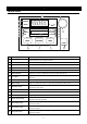
Description and Function of Each Part Control Panel 6 9 ERROR 10 DOOR ℃ STAND BY END HEATER FIXED TEMP AUTO-START AUTO-STOP PROGRAM 8 11 12 13 FAN 7 14 15 16 5 17 18 MODE PROGRAM MENU POWER 1 2 3 4 ① Mode Key Starts/releases the function menu. ② Program Key Starts/releases the program menu. ③ Menu Key Starts/releases the operation menu. ④ Power Key Turns ON/OFF the power. ⑤ Jog Dial Selects menu item and edit parameters.
Operation Method Preparation Connect power plug rightly The FP series has two specifications; for 100V and 200V depending on the electric capacity used. Make sure that a proper power terminal/power plug is plugged into an adequate distribution board/socket depending on the electric capacity. Refer to Page 6, “Choose a correct power distribution board or receptacle” for the electric capacity.
Operation Method Preparation Turn on earth leakage breaker Turn on the earth leakage breaker at the right side of device. ON The main indicator indicates “- - - -“, and after five seconds the sub indicator indicates the current date and time, e.g. “2000-09-17 12:01”,the fun rotates and the fan lamp lights on. ℃ STAND BY END HEATER 2000-09-17 12:01 FAN FIXED TEMP AUTO-START AUTO-STOP PROGRAM NOTE) The clock on device is not set at the factory shipment.
Operation Method Preparation (Continued) ℃ STANDBY END HEATER FIXED TEMP Standing by 2000-09-17 12:01 AUTO START AUTO STOP PROGRAM. FAN The main indicator indicates the in-furnace temperature and the ℃ lamp lights on. The sub indicator displays “standing by” and the standby lamp lights on. called the “standby state”. Pressing the power key again turns off the power. Setting with jog dial Jog dial is used to select the operation mode or to set temperature and clock.
Operation Method Selecting operation mode The following four operation modes are used. No. Operation mode Function Page 1 Fixed Temperature Operation The device controls the constant temperature. 13 2 Auto Start Operation The device starts operation at the specified time. 15 3 Auto Stop Operation The device stops operation at the specified time. 18 4 Program Operation The device starts programmed operation at the specified time.
Operation Method Fixed Temperature Operation Select operation mode Press the menu key. Turn the jog dial to indicate “Fixed temp OP.” on the sub indicator and then press the dial. ℃ FIXED TEMP Fixed temp OP. OP. mode choice AUTO START AUTO STOP PROGRAM Set temperature The screen displays the window to set temperature after the fixed temperature operation is determined. The sub indicator indicates “Setup Temp”. The numerical characters that indicate temperature blinks.
Operation Method Fixed Temperature Operation Observe temperature during operation The main indicator indicates the in-furnace temperature. STANDBY FIXED TEMP END Setup Temp 1150℃↑ AUTO START HEATER FAN 2000-09-17 13:25 AUTO STOP PROGRAM The current state of temperature control is shown with the indications below at the right end of sub indicator. ↑ : rising ↓ : falling → : stable (within ±2.5) Stop operation Press the power key to stop the operation.
Operation Method Auto Start Operation Select operation mode Press the menu key. Turn the jog dial to display “Auto-start OP.” on the sub indicator, then press the dial. ℃ FIXED TEMP Auto-start OP. OP.mode choice AUTO START AUTO STOP PROGRAM Set temperature The screen displays the window to set temperature after the auto start is determined. The sub indicator indicates “Setup Temp”. The numerical characters that indicate temperature blinks. Indicate the desired temperature.
Operation Method Auto Start Operation Set time The screen displays the window to set wait time to operate (period) or start time (the hour) after the set temperature is determined. When timer mode is set to ”Time”: wait time can be input. When timer mode is set to “Clock”: start time can be input. NOTE) The default setting is “Time”. Refer to Page 37 “Select timer mode”. Wait Time Wait time input window Auto-start OP. Start Time Start time input window 13:00 Auto-start OP.
Operation Method Auto Start Operation After the wait time or start time is determined, the blinking auto start lamp lights on and the standby lamp blinks instead in startup wait state on auto start mode. The sub indicator shows the set temperature and remaining time. STANDB Y FIXED TEMP END Setup Temp 1000℃ AUTO START HEATER FAN start,rear 10min AUTO STOP PROGRAM Start operation The device starts fixed operation when the remaining time shows “0”.
Operation Method Auto Stop Operation Select operation mode Press the menu key. Turn the jog dial to indicate the “Auto-stop OP.” on the sub indicator, then press the dial. ℃ FIXED TEMP Auto-stop OP. OP. mode choice AUTO START AYTO STOP PROGRAM Set temperature The screen displays the window to set temperature after the auto stop is determined. The sub indicator indicates “Setup Temp” and the numerical characters that indicate temperature blinks. ℃ FIXED TEMP Setup Temp 0℃ Auto-stop OP.
Operation Method Auto Stop Operation Set time The screen displays the window to set operation time or operation stop hour after the set temperature is determined. When timer mode is set to ”Time”: operation time can be input. When timer mode is set to “Clock”: operation stop hour be input. NOTE) The default setting is “Time”. Refer to Page 37 “Select timer mode”. Stop time Operation time input window Auto-stop OP. Stop time Operation stop hour input window 13:00 Auto-stop OP.
Operation Method Auto Stop Operation Select "Wait Function" The screen changes to the window to select “Wait Function” after the time/hour is set. Turning on the function temporarily stops the countdown of timer if the in-furnace temperature is lower than set temperature by 3℃ or more, or higher by 6℃ or more. The function is available only when the timer mode is set to “Time”. “Clock”, go to the next step. Turn the jog dial to select “ON” or “OFF” and then press it to determine.
Operation Method Program Operation Register the programs with the program menu before starting the program operation. Page 26 “Create New Program” for the registration of programs. Refer to the Select program mode Press the menu key. Turn the jog dial to indicate “Program OP.” on the sub indicator and then press the dial. ℃ FIXED TEMP Program OP. OP. mode choice AUTO START AUTO STOP PROGRAM If no program is set to the device, the buzzer sounds and the sub indicator indicates a message.
Operation Method Program Operation Wait time / start time for operation The screen changes to the window to edit wait time (period)/start time (the hour) after the program is determined. When timer mode is set to ”Time”: wait time can be edited. When timer mode is set to “Clock”: start time can be edited. NOTE) The default setting is “Time”. Refer to Page 37 “Select timer mode”. Set the desired time by turning the jog dial. Wait Time Wait time input window 30min Program OP.
Operation Method Program Operation Display during soak operation During the soak operation, the segment number and the remaining time of soak time are indicated alternately. In the case the device is in the waiting state, a message “Waiting” is indicated with blinking.
Operation Method Operating instructions for program menu The program menu has the three functions listed below. No. Name Function Page 1 Prepare Program Create a new program and resister it. 26 2 Edit Program Edits or checks the registered program. 27 3 Delete Program Deletes the registered program. 34 Select function of program menu Make sure that the power is turned on. Press the program key.
Operation Method Operating instructions for program menu Turn the jog dial to select the desired program menu. Press the dial to determine menu. The screen changes to the menu input window. Cancel operation Press the program key to cancel the program menu selected.
Operation Method Create New Program Select the “Prepare Program” menu Make sure that the remaining number of segment is not ‘0’. If not, delete one of the registered programs before creating a new program. Select the “Prepare Program” on the function selecting window in the program menu and then press the jog dial. ℃ FIXE D TEMP Prepare Program Entry 0 rest 16 AUTO START AUTO STOP゚ PROGRAM Select program number The screen changes to the program number selecting window.
Operation Method Edit Program Select “Edit Program” menu Make sure that any program(s) is (are) registered. ℃ FIXED TEMP Edit Program Entry 3 rest 10 AUTO START AUTO STOP PROGRAM Select the “Edit Program” on the function selecting window in the program menu and then press the jog dial. Select program number The screen changes to the program number selection window. The sub indicator indicates “Editing” and the number in the screen, which shows the program number, blinks.
Operation Method Edit Program Edit segment One segment has ten kinds of set item. (*:Optional function) No. Name Setting range 1 Ramp time Step, 1 minute to 999 hours, end 2 Set temperature Within the range of set temperature for the device 3 Soak time 0 minute to 999 hours, hold 4 Wait mode OFF, ON 5 Repeat starting segment None, registered segment number 1 to 16 6 Repeat time 1 to 999, infinite The conception of a segment is shown in the figure below.
Operation Method Edit Program Select set item The screen changes to the item selecting window after the program number is determined in the “Prepare Program” or “Edit Program”. Ramp time Ramp time P01-01 Setup temp Set temperature Soak time Wait mode Repeat start segment Repeat count Segment addition Program end P01-01 Soak time ► 30min rest 10 ► 100℃ rest 10 ► 30min P01-01 rest Wait ► OFF P01-01 rest Rep. start 10 10 ► S01 P01-01 rest 10 Rep.
Operation Method Edit Program Some set items are not indicated depending on the condition as shown in the list below, which means that the items are invalid in that condition. Item Ramp Time Indication Always indicated. Set Temperature Not indicated when the ramp time is in “End”. Soak Time Not indicated when the ramp time is in “End”. Wait Mode Not indicated when the ramp time is in “End” or soak time is in “Hold”.
Operation Method Edit Program Edit segment The segment is edited to the program number determined in Page 27 “Select program number”. ℃ FIXED TEMP Ramp time >STEP P01-01 rest 10 AUTO START AUTO STOP PROGRAM Select the set item and press the jog dial. value starts to blink.
Operation Method Edit Program Add segment Select the “Append seg” on the item selecting window and then press the jog dial. ℃ FIXED TEMP Append seg. P01-01 rest 10 AUTO START AUTO STOP PROGRAM NOTE) The ”Append seg” is not indicated in the following conditions; the ramp time for the last segment number is in “end”, the soak time is in “hold”, the repeat time is in “limitless”, the key lock mode is in “on”, or the program under edition is being executed.
Operation Method Edit Program End program edition Select the “Program End” on the items selecting window and then press the jog dial. ℃ FIXED TEMP Program End P01-01 rest 10 AUTO START AUTO STOP PROGRAM NOTE) Pressing the program key on the item selecting window is also possible.
Operation Method Delete Program NOTE) ・Make sure that any program(s) is (are) registered. ・Deleting the program under operation is impossible. Select “Delete Program” Select the “Delete Program” on the function selecting window in the program menu and then press the jog dial. ℃ FIXED TEMP Delete Program Entry 3 rest 10 AUTO START AUTO STOP PROGRAM Select program number The screen changes to the program number selecting window. desired program number to be deleted, then press it.
Operation Method Function menu The function menu has the seven functions listed below. (*:Optional function) No. Name Function 1 Timer Mode Sets the timer mode 37 2 Key Lock Mode Sets the key lock mode. 38 3 Buzzer Mode Sets the buzzer mode. 39 4 Calibration Offset Sets the calibration offset temperature. 40 5 Total Operating Hours Indicates the total operating hours. 41 6 Date/Time Sets the date and time. 42 7 Communication Lock out Sets the communication lock out mode.
Operation Method Function menu Select function Turn the jog dial to select the item indicated on the sub indicator. Timer mode Key lock mode Buzzer mode Timer mode ►time Key lock mode ►OFF Buzzer mode ►ON Calibrate ►±0℃ Calibration offset Total operating hours Date/Time Communication lock out mode Acc. time 49999hr Date ►2000-12-31 Time 23:59 Comm. Lockout Press the jog dial to select the function with the mode indicated.
Operation Method Function menu Select timer mode Indicate the “Timer mode” on the item selection window in function menu and them press the jog dial. ℃ FIXED TEMP Timer mode >time AUTO START AUTO STOP PROGRAM Select “Time” / “Clock” The “►” (cursor) disappears and the current mode blinks. Turn the jog dial to indicate “time” or “Clock”. Timer mode time ↓ Timer mode Clock Determine mode Press the jog dial.
Operation Method Function menu Select key lock mode Indicate the “KeyLock mode” on the item selection window in function menu and them press the jog dial. ℃ FIXED TEMP Keylock mode >OFF AUTO START AUTO STOP PROGRAM Select “ON” / “OFF” The “►” (cursor) disappears and the current mode blinks. Turn the jog dial to indicate “ON” or “OFF”. Keylock mode ON ↓ Keylock mode OFF Determine mode Press the jog dial.
Operation Method Function menu Select buzzer mode Indicate the “Buzzer mode” on the item selection window in function menu and them press the jog dial. ℃ FIXED TEMP Buzzer mode >ON AUTO START AUTO STOP PROGRAM Select “ON” / “OFF” The “►” (cursor) disappears and the current mode blinks. Turn the jog dial to indicate “ON” or “OFF”. Buzzer mode ON ↓ Buzzer mode OFF Determine mode Press the jog dial.
Operation Method Function menu Select calibration offset mode Indicate the “Calibrate” on the item selection window in function menu and them press the jog dial. ℃ FIXED TEMP Calibrate > ± 0℃ AUTO START AUTO STOP PROGRAM Input offset temperature The “►” (cursor) disappears and the current offset temperature blinks. Turn the jog dial to indicate desired temperature. Calibrate ±0℃ ↓ Calibrate +5℃ Determine mode Press the jog dial.
Operation Method Function menu Select “Acc. Time” NOTE) The “Acc. Time” is a function to check the total operating hour of device. changed. The content cannot be Turn the jog dial on the item selection window to indicate the “Acc. Time”. ℃ FIXED TEMP Acc. time 100hr AUTO START AUTO STOP PROGRAM The total operating hour from the factory shipment to the current time is indicated. Acc. time 100hr NOTE) The total operating hour means the total lapsed time when the power of device is not off.
Operation Method Function menu Put clock right NOTE) The time indicated on the clock is not correct at factory shipment. Before operating this unit, put the clock right. NOTE) The setting of clock cannot be changed at the startup wait state on auto start mode and under operation state on program mode. Press the “Power key” to stop the operation and reset the clock. Turn the jog dial on the item selection window in function menu to indicate the “Date” and “Time”.
Operation Method Function menu (continued) Select the desired item and press the jog dial. The “►” (cursor) disappears and the current set value blinks. the value. Date 2000-09-22 Time 17:30 Turn the jog dial to change ↓ Date 2001-09-22 Time 17:30 Press the jog dial. ℃ FIXED TEMP Date 2001-09-22 Time 17:30 AUTO START AUTO STOP PROGRAM The setting is determined and the window goes back to the item selection window in function menu.
Operation Method Function menu Select communication lockout mode Indicate the “Comm. Lockout” on the item selection window in function menu and them press the jog dial. ℃ FIXED TEMP Comm. Lockout ON AUTO START AUTO STOP PROGRAM Select “ON” / “OFF” The “►” (cursor) disappears and the current mode blinks. Turn the jog dial to indicate “ON” or “OFF”. Comm. Lockout ON ↓ Comm. Lockout OFF Determine mode Press the jog dial. ℃ FIXED TEMP Comm.
Operation Method Calibration Offset Function Description In the controller, the relationship between the temperature T detected by the sensor and the display temperature of the operation panel D is expressed by the equation of the line which DS passes the two points (T0, D0) and (TS, DS) shown in Fig.1.
Operation Method Independent overheating prevention device There are two safety devices in this unit: the auto-overheating preventive function of the controller (automatic recovery) and the independent overheating prevention device (manual recovery). Circuits and sensors that are independent from the controller configure them. These safety devices for the temperature overheating prevention protect the instrument in a fail-safe method.
Operation Method Temperature Rise/Fall (Reference Data) The following graph shows the data for temperature rise/fall of respective device types. The data shown is only reference because these values vary depending on the quantity of sample or an ambient temperature. Use the data for temperature rise/fall when creating programs. in-furnace temp. (℃) Temperature rising characteristics in FP series 1400 FP100 FP310 1200 FP410 1000 FP300 800 600 400 200 0 0 20 40 60 80 100 120 lapsed time (min.
Handling Precautions WARNING! If a problem occurs If smoke or strange odor should come out of this unit for some reason, turn off the power key right away, and then turn off the circuit breaker and the main power. Immediately contact a service technician for inspection. If this procedure is not followed, fire or electrical shock may result. Never perform repair work yourself, since it is dangerous and not recommended.
Handling Precautions Furnace may be cracked Though the furnace may be cracked when it is used with high temperature, this does not affect the use or performance of this unit. Open/close door in high temperature affects the device Do not open/close the door as possible at the in-furnace temperature of 500℃ or more, which affects the lives of sensor, oven and heater. Quickly open/close it after operation if necessary.
Maintenance Method Daily Inspection and Maintenance WARNING! • • • Disconnect the power cable from the power source when doing an inspection or maintenance unless needed. Perform the daily inspection and maintenance after returning the temperature of this unit to the normal one. Do not disassemble this unit. CAUTION! • • Use a well-drained soft cloth to wipe dirt on this unit. Do not use benzene, thinner or cleanser for wiping. Do not scrub this unit.
Long storage and disposal When not using this unit for long term / When disposing CAUTION! When not using this unit for long term… • Turn off the power and disconnect the power cord. WARNING! When disposing… • Keep out of reach of children. • Remove the door and driving parts. • Treat as large trash. Environmental protection should be considered We request you to disassemble this unit as possible and recycle the reusable parts considering to the environmental protection.
In the Event of Failure… Error Display When an error occurs, the buzzer sounds and the ERROR lamp blinks. The main indicator indicates the error number and the sub indicator indicates the detail of error and its corrective actions. Error No. Error Name Er00 Communication error Er.01 Temperature sensor error Er.02 TRIAC short-circuit Er.03 Heater disconnection Er.07 Independent overheating protection device is activated. Er.08 Timer element error Er.10 Main relay error Er.14 RAM error Er.
In the Event of Failure… Function of safety devices Safety device Over current earth leakage breaker Function Action Indication Possible cause / corrective action None Check the cause by contacting to our service division. Prevents over current and electric leakage. Power source is cut off. All indications lights off. Prevents overtemperature of device surface Heater circuit is cut off. Warning buzzer Combined with Contact to our service heater cutoff division.
In the Event of Failure… Troubleshooting Problem The sub indicator does not indicate current date and time when the electric leakage breaker is turned on. Possible Cause Power is not supplied. Bad condition of the earth leakage breaker Bad condition of the controller The cooling fan does not move when the electric leakage Bad condition of the cooling fan breaker is turned on. The operation panel indicates none when the power key is pressed. Temperature does not rise.
After Service and Warranty In Case of Request for Repair If the failure occurs, stop the operation, turn OFF the power switch, and unplug the power plug. Please contact the sales agency that this unit was purchased, or the Yamato Scientific's sales office. < Check following items before contact > ◆ ◆ ◆ ◆ Model Name of Product See the production plate attached to this unit.
Specification FP100 FP300 Operating temperature range (*1) FP310 100 to 1150℃ Temperature adjustment accuracy (*1) ±1.5℃ (@1150℃) Time required to reach highest temperature (*1) Approx. 80min.
Wiring Diagram FP100 FP300 Control panel ELB AC100V P2 P1 1 1 1 2 3 4 5 Tr X2 2 3 CR 4 SSR1 T1 T2 SSR2 J1 2 OH 3 1 2 X1 1 3 4 1 2 3 4 1 J2 6 1 2 1 5 6 J7 X1 X2 30 1 1 2 1 1 Fluorescent Display J1 PIO7 J2 12 11 12 J8 7 8 4 30 J22 1 2 3 4 5 6 J3 J4 J21 2 12 Jog dial J5 1 2 3 1 J19 3 Overheating prevention temp.
Wiring Diagram FP310 FP410 Control panel ELB AC200V P2 P1 1 1 Tr X2 2 T1 T2 3 CR T1 T2 4 SSR1 J1 SSR2 1 20 OH 3 CN 1 2 J1 1 2 3 4 J2 X1 1 2 3 1 J1 2 3 Overheating prevention temp.
Replacement Parts Table Common Use Parts Part Name Code No.
Replacement Parts Table FP300 Part Name Code No.
Replacement Parts Table FP410 Part Name Code No.
Reference List of Dangerous Substances Never use explosive substances, flammable substances and substances that include explosive or flammable ingredients in this unit.
Responsibility Please follow the instructions in this document when using this unit. Yamato Scientific has no responsibility for the accidents or breakdown of device if it is used with a failure to comply. Never conduct what this document forbids. Unexpected accidents or breakdown may result in. Note ◆ The contents of this document may be changed in future without notice. ◆ Any books with missing pages or disorderly binding may be replaced.