
Service manual


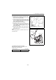


Table Of Contents
- Cover
- History of Revision
- FOREWORD
- CONTENTS
- FOR SAFETY
- 1. General
- 2. Inspection and adjustment
- 2.1 Periodic maintenance schedule
- 2.2 Periodic inspection and maintenance procedure
- 2.2.1 Check before starting
- 2.2.2 inspection after initial 50 hours or one month operation
- 2.2.3 Inspection every 50 hours or monthly
- 2.2.4 Inspection every 100 hours six months
- 2.2.5 Inspection every 150 hours or one year
- 2.2.6 Inspection every 250 hours or one year
- 2.2.7 Inspection every 1,000 hours or four years
- 2.3 Adjusting the no-load maximum or minimum speed
- 2.4 Sensor Inspection
- 2.5 Thermostat inspection
- 2.6 Adjusting operation
- 2.7 Long storage
- 3. Troubleshooting
- 4. Disassembly and reassembly
- 5. Inspection and servicing of basic engine parts
- 6. Fuel injection equipment
- 6.1 Fuel Injection pump/governor
- 6.1.1 Fuel system diagram
- 6.1.2 Fuel injection pump service data and adjustment
- 6.1.3 Fuel injection pump structure
- 6.1.4 Removing a fuel injection pump
- 6.1.5 Installing a fuel injection pump
- 6.1.6 Adjusting fuel injection timing
- 6.1.7 Troubleshooting of fuel injection pump
- 6.1.8 Major faults and troubleshooting
- 6.2 Fuel feed pump
- 6.3 Fuel filter
- 6.4 Fuel tank
- 6.1 Fuel Injection pump/governor
- 7. Intake and exhaust system
- 8. Lubrication system
- 9. Cooling water system
- 9.1 Cooling water system
- 9.2 Seawater pump
- 9.3 Fresh water pump
- 9.4 Heat exchanger
- 9.5 Pressure cap and coolant recovery tank
- 9.5.1 Pressure cap construction
- 9.5.2 Pressure cap pressure control
- 9.5.3 Pressure cap inspection
- 9.5.4 Replacing filler neck
- 9.5.5 Function of the coolant recovery tank
- 9.5.6 Specifications of coolant recovery tank
- 9.5.7 Mounting the coolant recovery tank
- 9.5.8 Precautions on usage of the coolant recovery tank
- 9.6 Thermostat
- 9.7 Bilge pump and bilge strainer (Optional)
- 10. Reduction and reversing gear
- 11. Remote control (Optional)
- 12. Electrical system
- 13. Service standards
- 14. Tightening torque for bolts and nuts
- Colophon
- Back cover

4. Disassembly and reassembly
99
(26) Mounting the lube oil filter.
Mount the lube oil filter with the tool of the filter case
remover.
(27) Mounting the seawater pump
1) Tighten the spacer bolt to the gear case cover.
2) Mount the bracket and the seawater pump
assembly to the gear case cover.
(28) Mounting the heal exchanger (exhaust manifold, fresh water tank unit).
Mount the gasket and heal exchanger (exhaust manifold).
Note:
After adjusting injection timing and tightening the fuel injection pump, mount the heat exchanger.
Because it is harder to tighten the fuel pump nuts after installing the heat exchanger.
Lube oil pressure
switch
Cylinder block
Lube oil filter
(Seawater pump)
Gear case cover
Spacer bolt
V-belt
Seawater pump
Bracket