
Service manual


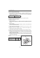


Table Of Contents
- Cover
- History of Revision
- FOREWORD
- CONTENTS
- FOR SAFETY
- 1. General
- 2. Inspection and adjustment
- 2.1 Periodic maintenance schedule
- 2.2 Periodic inspection and maintenance procedure
- 2.2.1 Check before starting
- 2.2.2 inspection after initial 50 hours or one month operation
- 2.2.3 Inspection every 50 hours or monthly
- 2.2.4 Inspection every 100 hours six months
- 2.2.5 Inspection every 150 hours or one year
- 2.2.6 Inspection every 250 hours or one year
- 2.2.7 Inspection every 1,000 hours or four years
- 2.3 Adjusting the no-load maximum or minimum speed
- 2.4 Sensor Inspection
- 2.5 Thermostat inspection
- 2.6 Adjusting operation
- 2.7 Long storage
- 3. Troubleshooting
- 4. Disassembly and reassembly
- 5. Inspection and servicing of basic engine parts
- 6. Fuel injection equipment
- 6.1 Fuel Injection pump/governor
- 6.1.1 Fuel system diagram
- 6.1.2 Fuel injection pump service data and adjustment
- 6.1.3 Fuel injection pump structure
- 6.1.4 Removing a fuel injection pump
- 6.1.5 Installing a fuel injection pump
- 6.1.6 Adjusting fuel injection timing
- 6.1.7 Troubleshooting of fuel injection pump
- 6.1.8 Major faults and troubleshooting
- 6.2 Fuel feed pump
- 6.3 Fuel filter
- 6.4 Fuel tank
- 6.1 Fuel Injection pump/governor
- 7. Intake and exhaust system
- 8. Lubrication system
- 9. Cooling water system
- 9.1 Cooling water system
- 9.2 Seawater pump
- 9.3 Fresh water pump
- 9.4 Heat exchanger
- 9.5 Pressure cap and coolant recovery tank
- 9.5.1 Pressure cap construction
- 9.5.2 Pressure cap pressure control
- 9.5.3 Pressure cap inspection
- 9.5.4 Replacing filler neck
- 9.5.5 Function of the coolant recovery tank
- 9.5.6 Specifications of coolant recovery tank
- 9.5.7 Mounting the coolant recovery tank
- 9.5.8 Precautions on usage of the coolant recovery tank
- 9.6 Thermostat
- 9.7 Bilge pump and bilge strainer (Optional)
- 10. Reduction and reversing gear
- 11. Remote control (Optional)
- 12. Electrical system
- 13. Service standards
- 14. Tightening torque for bolts and nuts
- Colophon
- Back cover

9. Cooling water system
167
9.5.4 Replacing filler neck
1) Take out the copper pipe inside the filler neck with striking a circumference with a driver and so on.
When the filler neck is removed, remove it with being careful not to damage the fresh water cooler,
and scrap it.
2) Clean both new filler neck and the insertion part of fresh water cooler. Apply T7471 type activator
or equivalent on both the surfaces and let it evaporate.
3) Apply Loctite 603 (improved 601) glue or
equivalent on filler neck outside contour and press
the filler neck into the fresh water cooler with the
special tool.
4) To fix the filler neck on the fresh water cooler,
press the small copper tube inside the filler neck
with the special tool.
Note:
The top of this tube should be under the sealing
surface of the filler neck for the pressure cap.
5) Fit the pressure cap on the filler neck.
Refer to 4.2.2 for tool 1 and tool 2.
Filler neck Part No. Copper tube Part No.
129673-44110 129673-44150
Press the filler neck
Filler neck
Tool1
Loctite 601Fresh water cooler
Filler neck
Filler neck
Tool 1
Tool 1
Filler neck
Tool 1
Press the copper tube
in the filler neck
Copper tube
Tool2