
Service manual
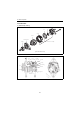
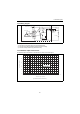


Table Of Contents
- Cover
- History of Revision
- FOREWORD
- CONTENTS
- FOR SAFETY
- 1. General
- 2. Inspection and adjustment
- 2.1 Periodic maintenance schedule
- 2.2 Periodic inspection and maintenance procedure
- 2.2.1 Check before starting
- 2.2.2 inspection after initial 50 hours or one month operation
- 2.2.3 Inspection every 50 hours or monthly
- 2.2.4 Inspection every 100 hours six months
- 2.2.5 Inspection every 150 hours or one year
- 2.2.6 Inspection every 250 hours or one year
- 2.2.7 Inspection every 1,000 hours or four years
- 2.3 Adjusting the no-load maximum or minimum speed
- 2.4 Sensor Inspection
- 2.5 Thermostat inspection
- 2.6 Adjusting operation
- 2.7 Long storage
- 3. Troubleshooting
- 4. Disassembly and reassembly
- 5. Inspection and servicing of basic engine parts
- 6. Fuel injection equipment
- 6.1 Fuel Injection pump/governor
- 6.1.1 Fuel system diagram
- 6.1.2 Fuel injection pump service data and adjustment
- 6.1.3 Fuel injection pump structure
- 6.1.4 Removing a fuel injection pump
- 6.1.5 Installing a fuel injection pump
- 6.1.6 Adjusting fuel injection timing
- 6.1.7 Troubleshooting of fuel injection pump
- 6.1.8 Major faults and troubleshooting
- 6.2 Fuel feed pump
- 6.3 Fuel filter
- 6.4 Fuel tank
- 6.1 Fuel Injection pump/governor
- 7. Intake and exhaust system
- 8. Lubrication system
- 9. Cooling water system
- 9.1 Cooling water system
- 9.2 Seawater pump
- 9.3 Fresh water pump
- 9.4 Heat exchanger
- 9.5 Pressure cap and coolant recovery tank
- 9.5.1 Pressure cap construction
- 9.5.2 Pressure cap pressure control
- 9.5.3 Pressure cap inspection
- 9.5.4 Replacing filler neck
- 9.5.5 Function of the coolant recovery tank
- 9.5.6 Specifications of coolant recovery tank
- 9.5.7 Mounting the coolant recovery tank
- 9.5.8 Precautions on usage of the coolant recovery tank
- 9.6 Thermostat
- 9.7 Bilge pump and bilge strainer (Optional)
- 10. Reduction and reversing gear
- 11. Remote control (Optional)
- 12. Electrical system
- 13. Service standards
- 14. Tightening torque for bolts and nuts
- Colophon
- Back cover

12. Electrical System
191
12.4.3 Wiring diagram
[NOTICE]
1) Don't do mis-connecting and short-circuit of each terminal.
2) Don't remove a battery terminal and a B terminal when rotating.
3) Shut out a battery switch during the alternator stop.
12.4.4 Standard output characteristics
The standard output characteristics of this alternator are shown as the below figure.
B
Stator coil
Diode
A
lternator
Rotor
coil
SL
F
P
E
1
IC regulator
E
Key
switch
BAT
Battery
Charge lamp
12V3.4W
P
IG
L
Condenser 2.2 F
0
20
100
80
60
40
Alternator speed (min
-1
)
Output current (A)
(Standard characteristics)
0 2 4 6 8 10 12 14 16 18 X 10
3
13.5V constant