
Service manual


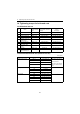

Table Of Contents
- Cover
- History of Revision
- FOREWORD
- CONTENTS
- FOR SAFETY
- 1. General
- 2. Inspection and adjustment
- 2.1 Periodic maintenance schedule
- 2.2 Periodic inspection and maintenance procedure
- 2.2.1 Check before starting
- 2.2.2 inspection after initial 50 hours or one month operation
- 2.2.3 Inspection every 50 hours or monthly
- 2.2.4 Inspection every 100 hours six months
- 2.2.5 Inspection every 150 hours or one year
- 2.2.6 Inspection every 250 hours or one year
- 2.2.7 Inspection every 1,000 hours or four years
- 2.3 Adjusting the no-load maximum or minimum speed
- 2.4 Sensor Inspection
- 2.5 Thermostat inspection
- 2.6 Adjusting operation
- 2.7 Long storage
- 3. Troubleshooting
- 4. Disassembly and reassembly
- 5. Inspection and servicing of basic engine parts
- 6. Fuel injection equipment
- 6.1 Fuel Injection pump/governor
- 6.1.1 Fuel system diagram
- 6.1.2 Fuel injection pump service data and adjustment
- 6.1.3 Fuel injection pump structure
- 6.1.4 Removing a fuel injection pump
- 6.1.5 Installing a fuel injection pump
- 6.1.6 Adjusting fuel injection timing
- 6.1.7 Troubleshooting of fuel injection pump
- 6.1.8 Major faults and troubleshooting
- 6.2 Fuel feed pump
- 6.3 Fuel filter
- 6.4 Fuel tank
- 6.1 Fuel Injection pump/governor
- 7. Intake and exhaust system
- 8. Lubrication system
- 9. Cooling water system
- 9.1 Cooling water system
- 9.2 Seawater pump
- 9.3 Fresh water pump
- 9.4 Heat exchanger
- 9.5 Pressure cap and coolant recovery tank
- 9.5.1 Pressure cap construction
- 9.5.2 Pressure cap pressure control
- 9.5.3 Pressure cap inspection
- 9.5.4 Replacing filler neck
- 9.5.5 Function of the coolant recovery tank
- 9.5.6 Specifications of coolant recovery tank
- 9.5.7 Mounting the coolant recovery tank
- 9.5.8 Precautions on usage of the coolant recovery tank
- 9.6 Thermostat
- 9.7 Bilge pump and bilge strainer (Optional)
- 10. Reduction and reversing gear
- 11. Remote control (Optional)
- 12. Electrical system
- 13. Service standards
- 14. Tightening torque for bolts and nuts
- Colophon
- Back cover

13. Service standards
201R1
13. Service standards
13.1 Engine tuning
No. Inspection item Standard Limit
Reference
page
1
Intake/exhaust valve clearance
mm
0.15-0.25 - 2.2.2(5)
2
V-belt tension
at 98N (10kgf)
mm
Between alternator
and F.W. pump
Used part 8-10 -
2.2.2(4)
New part 6-8 -
3
Fuel injection pressure
MPa (kgf/cm
2
)
12.3-13.28
(125-135)
- 2.2.7(2)
4
Compression pressure (at 250 min
-1
)
MPa (kgf/cm
2
)
3YM30
3.43±0.1
(35±1)
2.75±0.1
(28±1)
3.4
3YM20
2YM15
3.23±0.1
(33±1)
2.55±0.1
(26±1)
5
Cooling water Capacity
Liter (quart)
Engine
3YM30 4.9 (5.2) -
2.2.1(5)
3YM20 4.1 (4.3) -
2YM15 3.0 (3.2)
Coolant recovery tank 0.8 (0.8) -
6 Lube oil capacity (full)
3YM30 Liter (quart)
(at rake angle 8 degree)
2.8
0
/
-0.2
(3.0)
-
2.2.2.(2)
2.2.2.(3)
3YM20 Liter (quart)
(at rake angle 8 degree)
2.7
0
/
-0.2
(2.9)
-
2YM15 Liter (quart)
(at rake angle 8 degree)
2.0
0
/
-0.2
(2.1)
-
Marine gear KM2P-1
Liter (pint)
0.30 (0.64) -
3YM30C Liter (quart)
(at rake angle 0 degree)
2.5
0
/
-0.2
(2.6)
-
3YM20C Liter (quart)
(at rake angle 0 degree)
2.4
0
/
-0.2
(2.5)
-
2YM15C Liter (quart)
(at rake angle 0 degree)
1.8
0
/
-0.2
(1.9)
-
Sail drive SD20
Liter (pint)
2.2 (4.7) -
7
Lubricating oil pressure
MPa (kgf/cm
2
)
at rated speed
0.29-0.44
(3.0-4.5)
--
at low idle speed
0.06(0.6)
or above
- 8.2.5
8
Oil pressure switch operating pressure
MPa (kgf/cm
2
)
0.05±0.01
(0.5±0.1)
- 12.7.1
9Thermostat
valve opening
temperature
deg. C
69.5-72.5 -
2.5
Full opening lift (mm)
(temperature)
8 or above
(85 deg. C)
-
10
Thermo switch actuating temperature
(deg. C)
ON 93-97 -
2.4.2
12.7.2