OPERATION MANUAL Be sure to read this manual for safe and proper operation. Store this manual carefully after use.
Thank you for purchasing a Yanmar Marine Diesel Engine. [ INTRODUCTION ] • This Operation Manual describes the operation, maintenance and inspection, and handling precautions for the 4JH3-TE/-TCE/-HTE/-DTE Yanmar Marine Diesel Engine. 1. FOR SAFE OPERATION : Safety indications, safety precautions, explanation and use. 2. EXPLANATION OF PRODUCT : Specifications for this series and basic operation principles. 3. PREPARATION FOR OPERATION : Fuel oil, lube oil, cooling water, etc. check and supply. 4.
INDEX page No. 1 FOR SAFE OPERATION . . . . . . . . . . . . . . . . . . . . . . . . . . . . . . . . . . . . . . . . . . . . . . . . . 1 1.1 Warning Symbols . . . . . . . . . . . . . . . . . . . . . . . . . . . . . . . . . . . . . . . . . . . . . . . . . . . . . . . . . . . . . . . . . 1 1.2 Safety Precautions . . . . . . . . . . . . . . . . . . . . . . . . . . . . . . . . . . . . . . . . . . . . . . . . . . . . . . . . . . . . . . . . 2 1.3 Location of Product Safety Labels . . . . . . . . . . . . . . . .
5 MAINTENANCE & INSPECTION . . . . . . . . . . . . . . . . . . . . . . . . . . . . . . . . . . . . . . . . . 35 5.1 List of Periodic Inspections . . . . . . . . . . . . . . . . . . . . . . . . . . . . . . . . . . . . . . . . . . . . . . . . . . . . . . . . 36 5.2 Periodic Inspection Items . . . . . . . . . . . . . . . . . . . . . . . . . . . . . . . . . . . . . . . . . . . . . . . . . . . . . . . . . . 37 5.2.1 Inspection After Initial 50Hrs. Operation . . . . . . . . . . . . . . . . . . . . . . . . . . . .
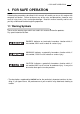
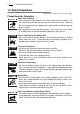
1. FOR SAFE OPERATION 1 1. FOR SAFE OPERATION Following the precautions described in this manual will enable you to use this engine with complete satisfaction. Failure to observe any of the rules and precautions, however, may result in injury, burns, fires, and engine damage. Read this manual carefully and be sure you fully understand it before beginning operation. 1.1 Warning Symbols These are the warning signs which are used in this manual and on the products. Pay special attention to them.
2 1. FOR SAFE OPERATION 1.2 Safety Precautions (Observe these instructions for your own safety.) Precautions for Operation Burns from Scalding • Never remove the filler cap of the fresh water cooler while the engine is still hot. Steam and hot water will spurt out and seriously burn you. Wait until the water temperature has dropped, then wrap a cloth around the cap and loosen it slowly. • After inspection, refasten the filler cap firmly.
1. FOR SAFE OPERATION 3 Alcohol • Never operate the engine while you are under the influence of alcohol or when you are ill or feel unwell as this results in accidents. Safety Precautions for Inspection Battery Fluid • Battery fluid is diluted sulfuric acid. It can blind you if it gets in your eyes, or burn your skin. Keep the fluid away from your body. Wash it off immediately with a large quantity of fresh water if you get any on you.
4 1. FOR SAFE OPERATION 1.3 Location of Product Safety Labels To insure safe operation, product safety labels have been attached. Their location is shown in the diagram below. Keep the labels from becoming dirty or torn and replace them if they are lost or damaged. Also replace labels when parts are replaced, ordering them in the same way as for the parts.
2. PRODUCT EXPLANATION 5 2. PRODUCT EXPLANATION 2.1 Use & Driving System This is light, compact diesel elngine for use in pleasure boats. The engine is equipped with a turbocharger and intercooler which insures maximum output while preserving lightness and compact size. (The 4JH3-TE /TCE are equipped with the turbocharger only.) Power output for this group of engines increases progressively from 4JH3-TE(4JH3-TCE), 4JH3-THE to 4JH3-DTE. In case of engine with marine gear.
6 2. PRODUCT EXPLANATION 2.2 Engine Specifications 2.2.1 4JH3-TE Engine model 4JH3-TE Use Pleasure boat Type Vertical water-cooled 4-cycle diesel engine No. of cyl.-bore×stroke 4-φ84×90 Displacement L 1.995 Aspiration Turbooharged Cont. rating kW{hp}/rpm 50.7(69) / 3700 Max. output kW{hp}/rpm (Crankshaft) *55.2(75)/3800 **53.5(72.
2. PRODUCT EXPLANATION 2.2.2 4JH3-TCE Engine model 4JH3-TCE Use Pleasure boat (Sailing boat) Type Vertical water-cooled 4-cycle diesel engine No. of cyl.-bore×stroke mm Displacement L Aspiration 4-φ84×90 1.995 Turbooharged Cont. rating kW{hp}/rpm 50.7(69)/3700 Max. output kW{hp}/rpm (Crankshaft) *55.2(75)/3800 **53.5(72.
8 2. PRODUCT EXPLANATION 2.2.3 4JH3-HTE Engine model 4JH3-HTE Use Pleasure boat Type Vertical water-cooled 4-cycle diesel engine No. of cyl.-bore×stroke 4-φ84×90 mm Displacement L 1.995 Aspiration Turbooharged Cont. rating kW{hp}/rpm 67.7(92)/3700 Max. output kW{hp}/rpm (Crankshaft) *73.6(100)/3800 **71.
2. PRODUCT EXPLANATION 9 2.2.4 4JH3-DTE Engine model 4JH3-DTE Use Pleasure boat Type Vertical water-cooled 4-cycle diesel engine No. of cyl.-bore×stroke 4-φ84×90 mm Displacement L 1.995 Aspiration Turbooharged Cont. rating kW{hp}/rpm 85.3(116)/3700 Max. output kW{hp}/rpm (Crankshaft) *91.9(125)/3800 **89.1(121.
10 2. PRODUCT EXPLANATION 2.3 Names of Parts • Operation Side (Right side as viewed from the propeller.
2. PRODUCT EXPLANATION 11 2.4 Major Servicing Parts Name of part Function Fuel filter Removes dust and water from fuel. The filter is a cartridge type, and the inner element should be replaced before clogging occurs. A water separator is on the bottom of the filter and should be drained periodically. Fuel priming pump This is a manual fuel pump. Moving the knob on the top of the fuel filter feeds the fuel. The pump is also used to bleed air from the fuel system.
12 2. PRODUCT EXPLANATION 2.5 Operation Equipment Explanation of the equipment used to operate the engine. 2.5.1 Instrument Panel OPTION The instrument panel is located in the cockpit, separate from the engine. The following instruments enable you to start and stop the engine and to monitor its condition during operation. ♦B type ♦New B type ♦C type ♦New C Type No.
2. PRODUCT EXPLANATION 13 (1) Meters The following meters are located in the upper center part of the instrument panel. ♦B/C and New B/C type panels use analog electric systems and have a pointer indicator. Turn the panel light switch (illumination switch) ON for easy viewing. • Tachometer The engine speed is indicated. Engine speed can be monitored. • Hour meter The number of hours of operation is indicated, and can be used as a guide for periodic maintenance checks.
14 2. PRODUCT EXPLANATION (3) Starter Switch This is the switch for starting engine operation. It is a rotary-type 3-step switch. Position is changed by turning the key in the switch. OFF ON is the position where the engine is stopped. All current is cut off. The key can be inserted and removed in this position. Stop position Drive position is the position for operation. Current flows to the instruments and alarm devices. START is the position for starting.
2. PRODUCT EXPLANATION 15 2.5.2 Remote Control Handle This engine is controlled by the remote control handle located in the cockpit. The speed control lever on the engine side and clutch lever on the marine drive are connected by remote control cable with the various remote control handles in the cockpit (We reccomend you a single hanrdle remote control device). There are the following kinds of remote control handles. When using other kinds of remote control devices, consult their operation manuals.
16 2. PRODUCT EXPLANATION Operation of the handle is as follows: • Starting and stopping Put the handle in NEUTRAL. This puts the clutch in the cut-off position (stop) and idles the engine at a low speed. • Forward Move the handle from NEUTRAL to ∆FWD(forward). This engages the clutch in forward and simultaneously increases the engine speed. Pushing the handle further in the same direction increases engine speed to full speed. • Reverse Move the handle from NEUTRAL to ∇REV(reverse).
2. PRODUCT EXPLANATION (2) Trawling Handle The trawling control is a single remote control handle. The marine gear trawling lever operates by remote control cable. The operation labels on the handle are: H:Highest trawling speed and normal (not trawling) operation position. L: Lowest trawling speed position. OPTION KMH4A Normal operation NOTICE: •Make sure to be the engine speed 1000rpm or less when trawling operation.
18 3. BEFORE OPERATION 3. BEFORE OPERATION Perform items 3.1 – 3.7 before starting to prepare for operation. 3.1 Fuel Oil, Lube Oil and Cooling Water 3.1.1 Fuel Oil (1) Selection of Fuel Oil Use the following diesel fuels or equivalents. Select fuels of a higher quality for best engine performance. • ISO 8217 DMA • BS 2869 A1 or A2 [Fuels eguivalent to Japanese Industrial standard, JIS. No. K2204-2] Cetane fuel number should be 45 or greater.
3. BEFORE OPERATION 19 3.1.2 Lube oil (1) Selection of Engine Lube Oil Use the following lube oil: *API Classification CD (Standards of America Petroleum Institute) *SAE Viscosity 15W40 (Standards of Society of Automotive Engineering) NOTICE: Using other than the specified lube oil will lead to seizure of parts inside the engine and gear device , abnormal wear, and shorten engine life. It will also effect the starting ability and power output.
20 3. BEFORE OPERATION 3.2 Supplying Fuel Fires from Oil Ignition • Be sure to use the correct type of fuel when refueling. Mistakenly filling with gasoline or the like will result in ignition. • Be sure to stop the engine before refueling. If you spill fuel, wipe such spillage carefully. • Never place oils or other flammable material close to the engine as this could result in ignition. 3.2.1 Filling the Fuel Tank Fill the tank with clean fuel which has not been contaminated with water or dust.
3. BEFORE OPERATION 21 3.3 Supplying Engine Lube Oil Fill with the specified amount of engine oil. 1. Remove the oil inlet cap on the top of the bonnet and fill with oil. 2. Remove the oil dipstick and check the level of the oil with the gauge on the stick. Oil should be filled to the upper mark on the dipstick gauge. Engine oil capacity: See 2.2 Engine Specifications. Oil Inlet Cap Dipstic Bonnet Dipstic Guide Oil Inlet 3. Replace the dipstick and tighten the oil inlet cap firmly by hand.
22 3. BEFORE OPERATION 3.5 Supplying Cooling Water Burns from Scalding • Never remove the filler cap of the fresh water cooler while the engine is still hot. Steam and hot water will spurt out and seriously bum you. Wait until the water temperature has dropped, then wrap a cloth around the cap and loosen it slowly. • After inspection, refasten the cap firmly. If the cap is not secure, steam or scalding water may be emitted during operation causing bums.
3. BEFORE OPERATION 23 3.6 Cranking When the engine is being used for the first time or if it has not been used for a long period of time, perform cranking before starting to distribute oil to all of the parts. Using an engine which has been stored for a long period of time without the cranking procedure may result in engine seizure, since there will no longer be oil on the moving parts after storage. 1. Open Kingston cock. 2.
24 4. HOW TO OPERATE 4. HOW TO OPERATE Alcohol • Never operate the engine while you are under the influence of alcohol or when you are ill or feel unwell as this results in accidents. Exhaust Gas Poisoning • Be sure to establish good ventilation in the engine room with windows, vents, or other ventilation equipment. Check again during operation to be sure that ventilation is good. Exhaust gas contains poisonous carbon monoxide and should not be inhaled.
4. HOW TO OPERATE 25 (4) Checking and Resupplying Marine Gear Oil 1. Check the marine gear oil level with the dipstick. 2. Supply with the recommended oil if necessary. Check the oil level with the dipstick while filling to the upper mark. →See 3.4 (5) Checking and Resupplying Cooling Water Burns from Scalding • Never remove the filler cap of the fresh water tank while the engine is still hot. Steam and hot water will spurt out and seriously burn you.
26 4. HOW TO OPERATE 4.2 Checking the Illumination Lamps of the Panel Meters Be sure to check the alarm devices and other instruments on the panel before and after starting the engine. If the devices are not working properly, it is impossible to prevent any problems arising from insufficient oil and water in the engine. Make checking the alarm and other devices before and after starting a regular practice. If having the optional instrument panel B or C or NewB or NewC, Refer to 2.5.1(2). 4.2.
4. HOW TO OPERATE 27 4.3 starting 4.3.1 Daily Starting Follow the following procedures for starting under normal conditions. 1. Open the Kingston cock. (option) 2. Open the fuel tank cock. (option) 3. Cut off all clutches and main switches for all auxiliary machinery so that there is no load. 4. Put the remote control handle in NEUTRAL. 5. Set the governor handle in the low speed position (when there is an independent governor remote control handle). 6. Turn on the battery switch. (option) 7.
28 4. HOW TO OPERATE 4.3.4 After the Engine has Started (1) Warming-up running After the engine has started, let it run for about 5 minutes. This warms up the engine and distributes oil to all of the parts. NOTICE: The engine will seize if it is operated when cooling seawater discharge is too small or if load is applied without any warming up operation.
4. HOW TO OPERATE 29 4.5 Clutch Operation for the Marine Gear FW D L TRA NEU RE V LOW HIGH D SPEED E SPE W LO ED E SP HI SPE GH ED L V NEUTRA FWD RE H HIG ED E W SP LO EED SP H SP IGH EE D Use the remote control handle to operate the clutch for the marine gear (FORWARD, NEUTRAL, REVERSE). • Be sure to run the engine at the lowest possible speed when changing between FORWARD and REVERSE. • Return the handle to NEUTRAL before moving it to another position.
30 4. HOW TO OPERATE 4.6 Check During Operation Always be on the lookout for problems during engine operation. Pay particular attention to the following. (1) Is sufficient water being discharged from the seawater outlet pipe? If the discharge is small, stop the engine immediately, identify the cause and repair. (2) Is the exhaust color normal? The continuous emission of black exhaust shows engine overloading. This shortens the engine’s life and should be avoided.
4. HOW TO OPERATE 31 4.7 Stopping the Engine Stop the engine in accordance with the following procedures. 1. Stop the boat. Put the remote control handle in NEUTRAL and reduce the engine speed to the lowest speed. 2. Be sure to race the engine before stopping it. →See 4.6(7) 3. Cool down the engine at low speed (1500rpm or lower) for about 5 minutes. 4. Continue to push the stop button until the engine is completely stopped.
32 4. HOW TO OPERATE 4.8 Operation Procedure The following diagram shows the procedures for operation explained up to this point. Parts of the operation may differ depending on the remote control system being used. Accompanying operation manuals should be read carefully and understood.
4. HOW TO OPERATE 33 4.9 Long-Term Storage 4.9.1 Before storing for long periods of time, perform the following. (1) Periodic Inspection If the time for a periodic inspection is close, perform it before storing the engine for a long period of time. (2) Draining the Cooling Water When not using antifreeze, be sure to drain the water from the inside of the engine.
34 4. HOW TO OPERATE ♦Draining the Water From the Fresh Water System If antifreeze has not been added to the fresh cooling water, be sure to drain the water from the fresh water system in the cold season. 1. Open the fresh water drain cocks at the following 4 positions and drain off the cooling water. 1) Side of the cylinder block 2) fresh water pump 3) turbocharger 4JH3-TE/-TCE 4) exhaust manifold or fresh water cooler 4JH3-HTE 4JH3-DTE 2. Close the drain cocks after draining the water.
5. MAINTENANCE & INSPECTION 35 5. MAINTENANCE & INSPECTION Conduct Periodic Inspection for Your Safety. The functions of engine components will degenerate and engine performance will fall according to the use of the engine. If countermeasures are not taken, you may encounter unexpected troubles while cruising at sea. Consumption of fuel or lube oil may become excessive and exhaust gas and engine noise may increase. These all shorten the life of the engine.
36 5. MAINTENANCE & INSPECTION 5.1 List of Periodic Inspections Daily and periodic inspection are important to keep the engine in its best condition. The following is a summary of inspection and servicing items by inspection interval. Periodic inspection intervals vary depending on the uses, loads, fuels and lube oils used and handling conditions, and are hard to establish definitively. The following should be treated only as a general standard.
5. MAINTENANCE & INSPECTION 37 5.2 Periodic Inspection Items 5.2.1 Inspection After Initial 50Hrs. Operation (1) Replacing the Engine Lube Oil and Lube Oil Filters (1st time) Precautions for Removing Hot Oil to Prevent Bums If extracting oil from the engine while it is still hot, do not let the oil splash on you. During initial operation of the engine, the oil is quickly contaminated due to the initial wear of internal parts. The lube oil must therefore be replaced early.
38 5. MAINTENANCE & INSPECTION (2) Replacing the Marine gear Oil and Washing the Oil Filters (1st time) Precautions for Removing Hot Oil to Prevent Bums If extracting oil from the engine while it is still hot, do not let the oil splash on you. During initial operation of the marine gear, the oil is quickly contaminated due to the initial wear of internal parts. The lube oil must therefore be replaced early. KMH4A Wash the lube oil filter at the same time. 1. Drain off the marine gear oil.
5. MAINTENANCE & INSPECTION 39 5.2.2 Inspection Every 50 Hours (1) Draining the Fuel Tank OPTION 1. Put a pan under the drain to catch the fuel. 2. Loosen the drain cock at the bottom of the fuel tank, and drain off any water and dirt collected inside. 3. Once the water and dirt have been drained off and the fuel coming out is clear, close the drain plug.
40 5. MAINTENANCE & INSPECTION (3) Inspection of Battery Fire due to Electric Short-Circuits Always turn off the battery switch or detach the earth cable (-) before inspecting the electrical system. Failure to do so could cause short-circuiting and fires. Proper Ventilation of the Battery Area Be sure the area around the battery is well-ventilated and there is nothing which could start a fire. During operation and charging, hydrogen gas is emitted from the battery and can be easily ignited.
5. MAINTENANCE & INSPECTION 41 5.2.3 Inspection Every 250 Hrs. or 1 yr. (1) Replacing the Fuel Filter Replace the fuel filter periodically before there is clogging and the fuel flow is reduced. 1. Close the fuel cock of the fuel tank. Tighten 2. Drain the fuel from the fuel drain cock at the bottom of the fuel filter. →See 5.2.2(2) 3. Remove the connectors of the wiring and remove the alarm switch using spanner. 4. Remove the fuel filter using the filter wrench. Loosen Fuel filter Filter wrench 5.
42 5. MAINTENANCE & INSPECTION (4) Replacing the Marine Gear Oil and Washing the Oil Filter (2nd time) Replace the marine gear oil for the 2nd time. Wash the filter at the same time. →See 5.2.1(2) KMH4A (5) Adjusting the Remote Control Handle The remote control handles and the engine speed control lever and clutch shifting lever are connected by an remote-control cable. Over time the cable becomes stretched and the connections loose causing deviation in the position which makes operation unsafe.
5. MAINTENANCE & INSPECTION 43 (5C) Adjusting the Position of the Trawling Remote Control Handle OPTION KMH4A 1. Check to see that the trawling lever on the marine gear side is in the high speed position when the trawling remote control handle is in H(high speed) position. 2. Check to see that the trawling lever on the marine gear side is in the low speed position when the trawling remote control handle is in L(low speed) position. 3.
44 5. MAINTENANCE & INSPECTION (7) Checking the Tension of the V-Belt of the Alternator When there is not enough tension in the V-belt, the belt will slip making it impossible for the alternator to generate power. Additionally, the fresh water pump will not work causing the engine to overheat. Check the tension of the V-belt in the following manner. 1. Press the V-belt down with your thumb at the middle of the belt to check the tension. The give in the V-belt should measure about 8∼10mm at the depression.
5. MAINTENANCE & INSPECTION 45 5.2.5 Inspection Every 1000 Hrs. or 4 yrs. (1) Replacing the Marine gear Oil and Washing the Lube Oil Filter (3rd time and thereafter) Replace the marine gear oil for the 3rd time after 1000 hrs. At the same time, wash the filter at the marine gear entrance. →See 5.2.1(2) KMH4A (2) Inspecting Inner Parts of the Seawater Pump The inside parts of the seawater pump will deteriorate with use, and discharge performance falls.
46 5. MAINTENANCE & INSPECTION (4) Checking and Replacing the fuel pipe and the cooling water pipe This maintenance requires specialized knowledge. Consult your Yanmar dealer or distributor. Check the hoses of the fuel and cooling water pipings and replace if damaged. (5) Replacing the Mixing Elbow This maintenance requires specialized knowledge. Consult your Yanmar dealer or distributor.
6. TROUBLE AND TROUBLESHOOTING 47 6. TROUBLE AND TROUBLESHOOTING 6.1 Simple problems and the appropriate countermeasures If you should encounter some difficulty during operation, refer to the following table for countermeasures. Trouble Probable Cause Measure ♦Alarm buzzer sounds and NOTICE: When the alarm equipment indicates a problem, immediately put the clutch in neutral and run the engine at low speed. Check to see which alarm indicator is lit, then stop the engine and inspect.
48 6. TROUBLE AND TROUBLESHOOTING Trouble Probable Cause Measure Reference Starting Failures Starter works. but engine does not start. Starter does not turn or turns too slowly (Can be turned by hand) Cannot be turned manually. No fuel Air in fuel line Bad fuel Replenish fuel; bleed. Bleed. Replace with recommended fuel. 3.2 3.2.2 3.1.1 Clogged fuel filter Poor fuel injection Pressure leakage from intake/exhaust valves Replace fuel filter. Ask for repairs. Ask for repairs. 5.2.
6. TROUBLE AND TROUBLESHOOTING 49 6.2 Emergency Repairs for Marine Gear Trouble If the marine gear should break, the boat will not run. In case of this emergency, follow the following procedure for using the clutch emergency bolt to return to port. Note:Cannot be used for KBW21 and KM4A marine gear. NOTICE: • Using the emergency bolt directly connects the clutch of the marine gear to the engine making it possible to turn the propeller.
50 6. TROUBLE AND TROUBLESHOOTING 6.3 Consulting Your Yanmar Dealer or Distributor Refer difficult problems and repairs to your Yanmar dealer or distributor. At the time of trouble, check and report the following. 1. Engine model and number [For engine name plate, see 2.3(Names of Parts).] 2. Boat name, hull material, boat size (tons) 3. Use, type of work, no. of hours run 4. Total no.
MEMO
52 7. SYSTEM DIAGRAM 7. SYSTEM DIAGRAM 7.1 Wiring diagram 7.1.1 B type Instrument Panel (Optional) 1/2 (Panel side) Starter switch Detail of coupler AA Color coding Engine stop switch Illumi. (lamp check) switch Starter SW Charge C.W. Temp. Eng. Oil Press.
7. SYSTEM DIAGRAM 53 2/2 (Engine side) (Customer) Battery (Cross sectional area of wire) 1 Battery SW Eng. stop mag. valve 3 2 Neutral SW Air heater Starter relay C.W. temp. SW Eng. oil press. SW Starter motor Alternator Earth bolt C.W. temp. sender Not available for B type Tacho sensor (Eng. oil press.
54 7. SYSTEM DIAGRAM 7.1.2 C type / C type × B type(No.2 station) Instrument Panel (Optional) 1/2 (Panel side) Starter switch Relay Engine stop switch Illumi. (lamp check) switch Starter SW C.W. Temp. Eng. Oil Press. Buzzer Tachometer Tacho M B type (No.2 station) Hour M Eng. Oil Press. M C.W. Temp. M C.W. Eng. Oil Charge Temp. Press. Eng. stop SW Starter SW Fuse (3A) Buzzer Switch Illumi. switch Buzzer C type Extension harness Harness No.
7. SYSTEM DIAGRAM 2/2 (Engine side) (Customer) Battery (Cross sectional area of wire) Eng. stop mag. valvee Battery SW 1 3 2 Neutral SW Air heater Starter relay C.W. temp. SW Eng. Oil Press SW Starter motor Alternator Earth bolt Tacho sensor C.W. temp. sendor Optional Color coding Detail of coupler AA Eng. Oil Press.
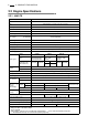
56 7. SYSTEM DIAGRAM 7.1.3 New B type Instrument Panel (Optional) 1/2 (Panel side) Starter switch Color coding Detail of coupler CC Detail of coupler AA Tachometer with hour meter Buzzer Buzzer stop Illumi. Eng. stop switch Starter switch Charge Eng.Oil Press. C.W. Temp. Sail Drive Leak Fuel Emp. Extension harness (Optional) Local supplied fuel empty sensor.
7. SYSTEM DIAGRAM 2/2 (Engine side) (Customer) Battery (Cross sectional area of wire) 1 Battery SW Eng. stop mag. valvee 3 2 Neutral SW Air heater Starter relay Starter motor C.W. Temp. SW Eng. Oil Press SW Alternator Tacho sensor Fuel filter Optional Local supplied sail drive leak sensor.
58 7. SYSTEM DIAGRAM 7.1.4 New C type / New C type × New B type(No.2 station) Instrument Panel (Optional) 1/2 (Panel side) Tachometer with hour meter Buzzer Relay Buzzer stop Illumi. Eng. stop SW Starter SW Eng. Oil Press. C.W. Temp. Sail Drive Leak Fuel Emp. New B typen (No.2 station) Tachometer Eng. press. M C.W. temp M with hour M Buzzer Buzzer stop Illumi. Eng. stop SW Starter SW Charge Eng. Oil. Press C.W. Temp. Sail Drive Leak Fuel Filter Fuel Emp. Extension harness Harness No.
7. SYSTEM DIAGRAM 59 2/2 (Engine side) (Customer) Battery (Cross sectional area of wire) 1 Battery SW Eng. stop mag. valvee 3 2 Neutral SW Air heater Starter relay C.W. Temp. SW Eng. Oil Press SW Starter motor Earth bolt Alternator Tacho sensor C.W. temp. sendor Optional Eng. Oil Press sendor Fuel filter Color coding Starter switch Local supplied sail drive leak sensor.
Operation Manual Models : Marine Engine Code No.
OVERSEAS OPERATIONS DIVISION 1-32, CHAYAMACHI, KITA-KU, OSAKA 530-8311, JAPAN TEL : 81-6-6376-6411 FAX : 81-6-6377-1242 YANMAR DIESEL AMERICA CORP. 951 CORPORATE GROVE DRIVE, BUFFALO GROVE, IL 60089-4508, U.S.A TEL : 1-847-541-1900 FAX : 1-847-541-2161 YANMAR EUROPE B.V. BRUGPLEIN 11, 1332 BS ALMERE-DE VAART, THE NETHERLANDS P.O.BOX 30112, 1303 TEL : 31-36-5493200 FAX : 31-36-5493209 YANMAR ASIA (SINGAPORE) CORPORATION PTE LTD. 4 TUAS LANE.