Electronic Control System Operation Manual for 6LY3 Series Engines ELECTRONIC CONTROL SYSTEM MANOPLYm01 Revision 3.
Notice to Boat Manufacturer, Installer, and Consumer Throughout this manual, warnings are used to alert the installer/operator to special instructions concerning a particular service or operation that may be hazardous if performed incorrectly or carelessly. Observe these alerts carefully! These “safety alerts” alone cannot eliminate the hazards that they signal.
Contents System Overview.......................................................................................................................................... 4 Helm Components...................................................................................................................................................4 Start Up.........................................................................................................................................................
System Overview Although the scope of this document relates to both single and dual engines, the instructions within depict the more widely used dual engine configuration.
Start Up Your electronic engine control system was configured at the factory with the default settings needed to initially start the system. See Appendix C. 1. Connect the battery terminals and turn the master battery switches to the “ON” position. Turn the engine control breaker switches on at the main breaker panel. Before starting the engines for the first time, take a moment to familiarize yourself with the shift and throttle controls and ignition switch.
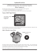
Start Up When powered-up, the i5601E Digital Displays will initially display an introductory screen showing the software revision level. They will then display one of the following four screens: These screens show all of the key engine data and can be accessed by pushing a single button. The right-most button allows the contrast and brightness to be set.
Start Up In the unlikely event that an engine fault occurs, a warning box appears in the display showing the cause of the fault, and the action to take, "Press Any Key To Continue." Pressing any key acknowledges the alarm and immediately switches the display to the Alarms screen. The i5601E continues to beep until all alarm conditions (engine faults) have cleared. Unacknowledged alarms are shown as flashing boxes.
Start Up Shift & Throttle Control Head Functions The Shift and Throttle Control Head comes with a dual function, single lever control. A single lever control initiates both shifting and throttle for a single engine. Control Head Operation WARNING The boat will start to move during the next steps. Be very cautious when first engaging the gears to establish that forward is truly forward and reverse is truly reverse. A quick in-and-out of gear test is recommended.
Operations Control Head Operation The boat will start to move during the next steps. Be very cautious when first engaging the gears to establish that forward is truly forward and reverse is truly reverse. A quick in-and-out of gear test is recommended. Ensure that the boat is clear of all obstacles forward and aft before conducting this test.
Operations NOTE: The flashing yellow N (Neutral) lamp can indicate status of either Shift Disconnect (SD) or Split Range Throttle (SRT). Please exercise caution when engaging/disengaging either of these modes! A steadyon Neutral lamp ALWAYS indicates engine is in NEUTRAL. Shift Disconnect (SD): Flashing yellow N (Neutral) lamp indicates SD engaged for this engine. Allows throttle control without gear engagement. TO ENGAGE Shift Disconnect: • • Move engine’s lever to the “Neutral” position.
Operations Sync Operations: note: Your system ships with Cruise Sync set as the default. Power Train Sync may be selected using the i5601E display. Cruise Sync (CS): Default Automatically synchronizes engine RPMs when levers are close together and above 20% forward throttle. A lit red SYNC lamp indicates sync is enabled. To Enable CS: • • Press SYNC button. (Red lamp flashes.) Match control handle positions within 10% of each other. (Red lamp goes steady when levers match — CS is now enabled.
Operations System Alarms Critical Alarms Continuous flashing both lights on either side of the control indicates a Critical Alarm. System will do a “Safe Shut Down,” and must be serviced before further use. When a critical alarm occurs, the system will automatically go to the selected “Fail Safe Response” mode. The system MUST be shut down and restarted for most critical alarms. Some functions may operate for a time after restart. See display on Control Unit to determine cause of alarm.
Operations Optional Trolling Mode Note: The Trolling Mode must be calibrated before trolling will operate properly. See Installation Manual. The Trolling mode option allows the boat operator to slow the forward and aft speed of the boat for fishing. Trolling mode is achieved by the ECU electronically adjusting pressure bypass valves in the gearbox, allowing the clutches to slip.
Operations i5601E Digital Display Alarms/Engine Diagnostic Codes Performs the function indicated by a pop-up menu, if present. With no pop-up menu showing, briefly press to display the Lighting & Contrast menu. With no pop-up menu showing, press and HOLD to display the MAIN MENU.
Operations Engine Alarms The Alarm Screen will display the status of 20 defined alarms. A flashing black background indicates unacknowledged alarm; a solid black background indicates an acknowledged still in alarm state status. Engine Diagnostic Codes This screen displays the diagnostic code information. The title bar indicates the number of diagnostic items. Maintenance Warning Based on startup issues, the maintenance timer will activate between 50 and 60 hours of operation.
Operations Diagnostics The digital display indicates if certain malfunctions occur. The system also stores certain DTC (Diagnostic Trouble Codes) for reference. These codes will help you or a technician to determine which subsystem has malfunctioned. Display and record all Trouble Codes so you can relay them to the technician. A listing of possible Diagnostic Trouble Codes are in Appendix E. There are also diagnostic lights built into the Electronic Control System to assist in troubleshooting.
Appendix A i5601E Digital Display Setup The i5601E was set up at the factory with the keys assigned and locked as shown on page 6 of this manual. This mode is the default mode and allows start up and operation of the engine. It serves many applications quite well. The i5601E Digital Display unit has many additional features and capabilities. This section of the book shows the use of some of these features. Changing the basic set up is typically accomplished in one of two ways. 1.
Appendix A Display Settings The Monitor Settings Menu allows setting of parameters that are specific to the display unit. Some settings such as Language and Lighting will be communicated to the other displays.
Appendix A User Settings and Factory Settings • • The user setting allows for reset of the maintenance timer. The factory settings require a password to change. “Unlocking” the Hot Keys This is a popular way to expand the use of the i5601E. The default hot keys will remain active but you can select other data parameters in the various display areas. A right arrow becomes visible over key 5. Pushing that key then allows for selection of a number of data types in the various boxes.
Appendix A Quad Screen Parameters These data choices can be placed in any box of a quad screen or in the two small boxes of an engine data screen: The screen headings that are included in a standard (default) set-up are noted in bold.
Appendix B i5601E Menu Navigation Performs the function indicated by a pop-up menu, if present. With no pop-up menu showing, briefly press to display the Lighting & Contrast menu. With no pop-up menu showing, press and HOLD to display the MAIN MENU.
Appendix C Default Settings For single engine configuration, the engine interface part number is i8320 (no trolling) or i8325 (with trolling). The settings are the same as the dual engine configuration below. Without Trolling Engine Interface part number i8320P i8320S Idle RPM 700 700 Sync Cruise Cruise Lead Engine Port Port Split Range Throttle 25% 25% Forward Throttle Curve F5 F5 Reverse Throttle Curve R1 R1 Programmable Shift Delay 7.2 7.2 Fixed Shift Delay 0.2 0.
Appendix D Fuses There is a fuse on the back of both the lower station and upper Station Ignition Switch Panels. It is a 5 amp fuse, designation AGC SA.
Appendix E Diagnostic Trouble Code Descriptions NOTE: On the digital display the DTC “Y” code will be shown along with additional information for that code. This information will further define the fault. Please make note of all the information details with the Y code before notifying your Yanmar service technician.
Appendix F Network Status The i5601E has several screens to help technicians diagnose errors on the NMEA 2000® Data Bus. See i5601E Operation on page 17 and Menu Navigation on page 21 to locate this screen. Network Status Display Accesses the Network Status Display Screen. The purpose of the display is to show details of the Network and allow determination of Network Problems. (The values are constantly monitored and do not rely on the screen being displayed.
Appendix G Station Select Protection Station Select Protection prevents accidental switching between control stations on multi-stationed boats. If turned on, a change of control stations requires that control head buttons be pressed in a specific sequence SELECT, SELECT, NEUTRAL, SELECT to change stations. The menu options are: • • Station Select Protection Off (N) (Default Setting). Station Select Protection On (Y).
Yanmar Marine International B.V. P.O. Box 30112, 1303AC Almere, The Netherlands Brugplein 11, 1332 BS Almere-De Vaart, The Netherlands Phone: +31 36-5493200 Fax: +31 36-5493209 Yanmar Co., Ltd Head Office 1-32, Chayamachi, Kita-Ku, Osaka 530-8311, Japan Yanmar Marine USA Corporation 101 International Parkway, Adairsville, GA 30103, USA Phone: +1 770-877-9894 Fax: +1 770-877-7565 Yanmar Asia (Singapore) Corporation Pte Ltd. 4 Tuas Lane.