Safety • Assembly • Operation • Tips & Techniques • Maintenance • Troubleshooting • Parts Lists • Warranty A O AL / / / / *Model462 Shown Chipper Shredder- Model Series 452 thru 465 IMPORTANT READ SAFETY RULES AND iNSTRUCTiONS CAREFULLY BEFORE OPERATION Warning: This unit isequippedwithan internalcombustionengineand shouldnot be usedon or nearany unimprovedforest-covered,brushcoveredor grass-coveredland unlesstheengine'sexhaustsystemis equippedwith a sparkarrestermeetingapplicablelocalor statel
This Operator's IVlanual is an important pare and maintain part of your new chipper the unit for best performance. Please shredder, it wiil help you assemble, read and understand pre= what it says. Table of Contents Customer Support .............................................. 2 Safety Labels ...................................................... 3 Safe Operation Practices ................................... 4 Setting UpYour Chipper Shredder ....................
TO AVOID SERIOUS iNJURY: TO AVOID SERIOUS iNJURY: • • Do not operate on uneven ground where unit is unstable, other hard surfaces To avoid a fire hazard, keep leaves, grass, and other combustible muffler, materials • Keep children • operation, Wear approved the owner's Keep all shields attached.
WARNING: Engine Exhaust, some of its constituents, and certain vehicle components contain or emit chemicals known to State of Californiato cause cancer and birth defects or other reproductiveharm. DANGER: This machine was built to be operated according to the rules for safe operation in this manual. As with any type of power equipment, carelessness or error on the part of the operator can result in serious injury. This machine is capable of amputating hands and feet and throwing objects.
Operation Maintenance & Storage 1. Donot put hands andfeet near rotatingpartsor in the feedingchambersand dischargeopening.Contactwith the rotatingimpellercan amputatefingers, hands,andfeet. 2. Beforestartingthe machine,makesurethe chipperchute, feed intake,and cuttingchamberare empty andfree of all debris. 1. Nevertamper withsafetydevices.Checktheir proper operationregularly. 2. Checkbolts and screwsfor propertightness at frequent intervalsto keepthe machinein safe workingcondition.
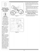
IMPORTANT:This unit is shippedwithoutgasolineor oil in theengine.Be certainto serviceenginewith gasoline and oil as instructedin the separateengine manual beforeoperatingyour machine. Loose Parts In Carton a. HopperAssembly d. Bag b. Chute Deflector e. SafetyGlasses c. ChipperChute f. EngineOil Attaching The Hopper Shredder Assembly 1. a. Removesix hexnuts and washersfrom the weld studson the impellerhousing.Donot removethe supportplate. See Figure3-1. b.
Attaching The Chute Deflector 3. a. Removethe wingknobs fromeach sideof the lower impellerhousing. b. Removethe hexlock nut,spacers,andhex boltfrom the topof theimpellerhousing.SeeFigure3-3. 4. a. Align the chutedeflectorin positionon the dischargeopeningand inserthex boltwith spacer throughhingeon chutedeflector(spacersfit inside of hinges).See Figure314. b. Placesecondspaceroverhex bolt insideother hingeand securewith hex lock nut. c.
7. Thechippershredderwas shippedwith one end of the supportbracealreadysecuredto the lowerframe. Loosenbut do not removethebolts securingthe brace to the frame.See Figure3-7. / / / / ji // // /// a. Align the holesin the chutewith the holes in the top of the braceand attachbraceto chipperchute with hardwarepreviouslyremoved.Tightensecurely. b. Tightenthe bolts securingthe supportbraceto the frame. // Setting u p / c.
f 9. a. Align the chipperchute overthe weldstuds, sothe slot in the bottomof the chuteis facing down. b. Securechipperchute with the threecupped washers(cuppedsideagainstthe chipperchute) and hexnuts previouslyremoved.Tightenthe nuts at this time.See Figure3-9. / / Attaching The Bag Setting 10.Toattachthe bag: Up YourChippe a. Placethe openingof the bag completelyover the chute deflector. Shredder b. Pullon the drawstringuntilthe bag is tight around chute deflectoropening. c.
m Know Your Chipper Shredder HopperAssembly ReleaseRod Oil Fillt Chipper Chute WARNING I i i i The operation of any chipper shredder can result in foreign objects being thrown intothe eyes, which can damage your eyes severely. Always wear the safety glasses provided with this unit or eye shields before chipping or shredding and while performing any adjustments or repairs.
This OperatorsManualcoversa rangeof product f specificationsforvariousmodels.Characteristicsand features discussedand/or illustratedin this manualmay not _ _ be applicableto all models.MTDLLCreservesthe right to changeproductspecifications,designsand equipment withoutnoticeand withoutincurringobligation. ._1__ Starting Engine /, _ _ -=] | | _11111_ _ ( WARNING:Never run the engine indoorsor in a poorlyventilatedarea.
Lubrication 1. Lubricatethe releaserodand springwith lightoil once a season.See Figure5-1. 2. Lubricatethe pivot pointson the hopperassemblywith lightoil oncea season.See Figure5-1. points before reassembly. 3. Lubricatethe pivot pointson the dischargechute with lightoil oncea season.See Figure5-1. 4. Followtheaccompanyingengine manualfor lubrication scheduleand instruction for engine lubrication. Your Chipper Shredder Engine Care 1. Maintainoil levelas instructedin enginemanual. 2.
6. Removethe blade by removingthe internalhex screws,lockwashers,and hexnuts which secureit to the impeller.Retainthe hardware.See Figure5-3. NOTE: Usea 3/16"hex key (Allen)wrenchon the outside of the blade and a 1/2" box(or socket)wrenchon the insideof the impeller.HoldtheAllen wrenchstationary and rotatethe box(or socket)wrenchto loosenthe nut. Your Chipper ,redder 7. Installa replacementblade (PartNo. 781-0490)with the hardwareremovedearlieror sharpen.
Problem Cause Enaine f., ailsto Start I Remedy Throttle levernotin correctStarting i thrott, Move post on (f equ pped) e everto FASTor STARTpost on 2, Sparkp!ugwire disconnected, 2, Connectwire tospark p!ug, choke notincHoKE position (if cHOKE equipped): poSiti0nl Fueltank emptyor Sta!efuel. &Engine not pdmed(if equipped)Prime tank with clean,freShgasolinel engineas .instructedin 6 Faut ark _ ysp P g: 6 ceanadjuStgap 0rrepace Blocked fuel 81Engine flooded, Engineruns erratic .
NOTES Use this page to make notes and write down important information.
Model Series 452 Thru 465 j_ i •¢/i 16
Ref. No, PartNo. Description 1. 736-0217 Lock Washer,3/8 2. 714-0149B CotterPin 3. 681-0048 WingKnob5/16-18 4. 681-0094 ChuteDeflectorAssembly 5. 711-0835 ClevisPin 6. 781-0457 ShredderScreen 7. 726-0211 U-Nut5/16-18 8. 750-0793 Spacer 9. 712-3027 Hex Lock Nut 1/4-20 10. 712-3004A Hex Lock Nut5/16-18 11. 736-0119 Lock Washer5/16 12. 681-0117 InnerImpellerHousingAssembly 13. 710-3025 Hex CapScrew5/16-18x.625 14. 710-0157 Hex CapScrew5/16-24x.75 15.
iVlodel Series 452 Thru 465 (16 1 ft ModelSeries454 & 464 :l:{ ModelSeries452 & 462 * If Equipped 18
Ref. No. Part No. Description 1. 728-0175 Pop Rivet 2. 731-1899 ChipperShredderChute 681-0095{H ChipperShredderChute 3. 735-0249 Chute Flap 4. 781-0633 Chute FlapStrip 5. 681-0068A 6. 710-0751 Hex CapScrew 1/4 -20x.620 7. 712-3027 Hex Lock Nut 1/4-20 8. 710-0106 Hex CapScrew 1/4-20x 1.25 9. 736-0173 FlatWasher.28ID x.74OD . ChipperChuteAssembly 10. 736-0242 Bell Washer.340ID x.872OD 11. 712-3010 Hex Nut5/16-18 12. 749-1004 SupportBrace 13.
MANUFACTURER'S LiMiTED WARRANTY The limitedwarrantyset forth belowisgivenby MTDLLCwith respect to newmerchandisepurchasedand usedin the UnitedStates,its possessionsand territories. "MTD"warrantsthis productagainstdefectsin materialand workmanshipfor a periodof two (2) years commencingon the date of original purchaseand will, at its option,repairor replace,freeof charge,any part foundto be defectiveinmaterialsor workmanship.