Operator’s Manual Single Stage Snow Thrower Models 285 & 295 Models E285 &E295 IMPORTANT: Read safety rules and instructions carefully before operating equipment. Warning: This unit is equipped with an internal combustion engine and should not be used on or near any unimproved forestcovered, brush-covered or grass-covered land unless the engine’s exhaust system is equipped with a spark arrester meeting applicable local or state laws (if any).
TABLE OF CONTENTS Content Page Important Safe Operation Practices .................................................................................. 3 Assembling Your Snow Thrower ....................................................................................... 5 Know Your Snow Thrower................................................................................................. 6 Operating Your Snow Thrower ..........................................................................................
SECTION 1: IMPORTANT SAFE OPERATION PRACTICES WARNING: This symbol points out important safety instructions which, if not followed, could endanger the personal safety and/or property of yourself and others. Read and follow all instructions in this manual before attempting to operate this machine. Failure to comply with these instructions may result in personal injury. When you see this symbol—heed its warning.
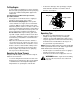
5. 6. 7. 8. 9. 10. 11. 12. 13. 14. 15. 16. 17. 18. 19. 20. Maintenance & Storage Never run an engine indoors or in a poorly ventilated area. Engine exhaust contains carbon monoxide, an odorless and deadly gas. Do not operate machine while under the influence of alcohol or drugs. Muffler and engine become hot and can cause a burn. Do not touch. Exercise extreme caution when operating on or crossing gravel surfaces. Stay alert for hidden hazards or traffic.
SECTION 2: ASSEMBLING YOUR SNOW THROWER Unpacking From Carton • • • • Cut along corners of the carton and lay it down flat. Remove packing material. Remove any loose parts included with unit (i.e., operator’s manual, etc.). Roll unit out of carton. Check carton thoroughly for any remaining loose part. • Raise the upper handle in the direction shown in Figure 1 until it clicks into the operating position. Make sure not to pinch or crimp the cable. Tighten the hand knobs.
SECTION 3: KNOW YOUR SNOW THROWER WARNING: Be familiar with all the controls on the snow thrower and their proper operation. Know how to stop the machine and disengage them quickly. Auger Control Handle Recoil Starter Gasoline Cap Fuel Plug Primer Key Electric Starter(If Equipped) Spark Plug Access Discharge Chute Oil Fill Plug Choke Lever Auger Shave Plate Figure 3 Auger Control Handle Primer Button Located on the upper handle, the auger control handle is used to engage and disengage the auger.
SECTION 4: OPERATING YOUR SNOW THROWER Before Starting • • WARNING: Read, understand, and follow all instructions and warnings on the machine and in this manual before operating. • The spark plug wire was disconnected for safety. Attach spark plug wire to spark plug before starting. • Gas and Oil Fill-Up • • Check oil and gasoline level and add if necessary. Follow related instructions in the separate engine manual packed with your snow thrower. WARNING: Use extreme care when handling gasoline.
To Stop Engine • • To stop engine, turn ignition key counter-clockwise. Disconnect the spark plug wire from the spark plug to prevent accidental starting while equipment is unattended. To help prevent possible freeze-up of starter, proceed as follows: • • • • Wing Knob Upper Chute Run engine for a few minutes before stopping to help dry off any moisture on the engine. Electric Starter (If Equipped): Connect power cord to switch box on engine, then to 120 volt AC receptacle.
SECTION 5: MAKING ADJUSTMENTS WARNING: NEVER attempt to make any adjustments while the engine is running, except where specified in the operator’s manual. Shave Plate • To check the adjustment of the shave plate, place the unit on a level surface. See Figure 6. The wheels, shave plate and augers should all contact level surface. Note that if the shave plate is adjusted too high, snow may blow under the housing.
SECTION 6: MAINTAINING YOUR SNOW THROWER Replacing Shave Plate WARNING: Before servicing, repairing, or The shave plate is attached to the bottom of the auger housing and is subject to wear. It should be checked periodically. There are two wearing edges and the shave plate can be reversed. Refer to Figure 6. inspecting, disengage the auger control bail and stop engine. Wait until all moving parts have come to a complete stop.
SECTION 8: TROUBLESHOOTING GUIDE Problem Cause Remedy Engine fails to start 1. 2. 3. 4. 5. 6. 7. Fuel tank empty, or stale fuel Blocked fuel line Key not in ON position Spark plug wire disconnected Faulty spark plug Engine not primed Engine flooded with excessive priming Engine runs erratic 1. Unit running on choke 2. Fuel line blocked, or stale fuel 1. 2. 3. 4. 5. Fill tank with clean fresh gasoline. Clean fuel line Insert key and turn to ON position Connect wire to spark plug.
SECTION 9: PARTS LIST FOR MODELS 285, E285, 295 & E295 41 39 35 44 46 35 32 35 44 44 51 38 45 40 52 24 49 26 33 47 43 17 42 12 50 48 12 17 37 18 8 14 3 11 21 34 20 36 CABLE TO BE ABOVE WHEEL AXEL 21 10 28 2 22 3 53 16 14 7 2723 31 4 1 29 13 25 17 13 9 12 22 10 9 28 30 19 15 12 6
Models 285, E285, 295 & E295 REF. NO. 1 2 3 4 5 6 7 8 9 10 11 12 13 14 15 16 17 18 19 20 21 22 23 24 25 26 27 PART NO. 684-04027 684-04028 710-0134 710-0167 710-0323 710-0352 710-0597 710-0642 710-0896 710-1005 712-0324 712-3010 712-3027 726-0299 731-1033 732-0357A 736-0119 736-0176 736-0326 736-0329 736-3090 741-0600 741-0919 746-04091 748-0234 749-04114 750-04230 REF. NO. 28 29 30 31 32 33 DESCRIPTION Auger Ass'y 21" complete w/Solid Shaft Auger Housing Ass’y 21” Screw, 1/4-20 x .
Models 285, E285, 295 & E295 9 3 11 11 4 1 8 2 5 6 12 10 7 REF. NO. 1 2 3 4 5 6 7 8 9 10 11 12 PART NO. 710-04071 710-0451 712-3068 720-0284 731-04127 731-04353 731-04373 731-04388 731-04429 732-04111 736-0159 684-04049 DESCRIPTION Carriage Screw, 5/16-18 x 1.0 Carriage Bolt, 5/16-18 x.075 GR 1 Hex Patch I-Nut 5/16-18‘ Handle Knob Assembly 5/16-18 Lower Chute 5” Dia Ring-Lower Chute Chute, Adapter 5” Dia Handle-Chute 5” Dia Upper Chute w/Export Label Chute Adjustment Spring Flat Washer,.
Models 285, E285, 295 & E295 18 16 1 19 5 12 10 17 9 7 8 13 6 3 21 15 21 14 23 4 22 2 20 REF. NO. 1 2 3 4 5 6 7 8 9 10 12 13 14 15 16 17 18 19 20 21 22 23 PART NO. 629-0071 710-0157 710-0409 710-0654A 710-0751 710-1003 712-0324 719-0581 726-0205 726-0470 731-2825 736-0119 736-0242 736-0337 747-04169 751-0535 751-0603 751-10023 751-0101A 756-04060 756-0475 790-00047 DESCRIPTION Extension Cord Hex Screw, 5/16-24 x .75 Hex Screw, 5/16-24 x 1.75 Self Tapping Screw, 3/8-16 x 1.
MANUFACTURER’S LIMITED WARRANTY FOR: The limited warranty set forth below is given by MTD LLC with respect to new merchandise purchased and used in the United States, its possessions and territories. “MTD” warrants this product against defects in material and workmanship for a period of two (2) years commencing on the date of original purchase and will, at its option, repair or replace, free of charge, any part found to be defective in materials or workmanship.