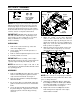
OPERATOR’S MANUAL SNOW THROWER MODELS E600E, E610E E640F, E660G E6C0F IMPORTANT: READ SAFETY RULES AND INSTRUCTIONS CAREFULLY Warning: This unit is equipped with an internal combustion engine and should not be used on or near any unimproved forestcovered, brush-covered or grass-covered land unless the engine’s exhaust system is equipped with a spark arrester meeting applicable local or state laws (if any). If a spark arrester is used, it should be maintained in effective working order by the operator.
SECTION 1: FINDING YOUR MODEL NUMBER This Operator’s Manual is an important part of your new snow thrower. It will help you assemble, prepare and maintain the unit for best performance. Please read and understand what it says. Before you start to prepare your snow thrower, please locate the model plate on the equipment and copy the information from it to the space provided below.
SECTION 3: IMPORTANT SAFE OPERATION PRACTICES WARNING: THIS SYMBOL POINTS OUT IMPORTANT SAFETY INSTRUCTIONS WHICH, IF NOT FOLLOWED, COULD ENDANGER THE PERSONAL SAFETY AND/OR PROPERTY OF YOURSELF AND OTHERS. READ AND FOLLOW ALL INSTRUCTIONS IN THIS MANUAL BEFORE ATTEMPTING TO OPERATE YOUR SNOW THROWER. FAILURE TO COMPLY WITH THESE INSTRUCTIONS MAY RESULT IN PERSONAL INJURY. WHEN YOU SEE THIS SYMBOL, HEED ITS WARNING.
repairs, adjustments, or inspections. Never place your hand in the discharge or collector openings. Use a stick or wooden broom handle to unclog the discharge opening. • Never direct discharge at bystanders or allow anyone in front of unit. • Disengage power to collector/impeller when transporting or not in use. • Take all possible precautions when leaving the unit unattended. Disengage the collector/impeller, shift into neutral, stop the engine, and remove the key.
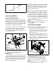
SECTION 4: ASSEMBLY AUGER SHEAR BOLTS (SPARES) Cupped Washer Shear Bolts (710-0890A) Upper Handle Carriage Bolt Hex Lock Nuts 5/16” Thread (712-0429) Wing Nuts NOTE: The augers are secured to the spiral shaft with two shear bolts and hex lock nuts. If you hit a hard foreign object or ice jam, the snow thrower is designed so that the bolts may shear. Two replacement shear bolts and nuts are provided for your convenience. Store in a safe place until needed.
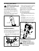
Lamp Wire Now release the traction control, and push the unit again. Move the shift lever back to the fast reverse position, then all the way forward again. There should be no resistance in the shift lever, and the wheels should keep turning. Alternator Lead If you have resistance when moving the shift lever or the wheels stop when they should not, loosen the jam nut on the traction control cable and unthread the cable one turn.
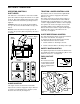
SECTION 5: OPERATION OPERATING CONTROLS SHIFT LEVER TRACTION / AUGER CONTROL LOCK The traction control is located on the right handle. Squeeze the control to engage the wheel drive. Release to stop. This same control also locks the auger control so you can turn the chute directional control without interrupting the snow throwing process. If the auger control is engaged with the traction control engaged, the operator can release the auger control (on the left handle) and the augers will remain engaged.
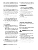
THROTTLE CONTROL Recoil Starter: The throttle control is located on the engine. It regulates the speed of the engine. See Figure 10. 5. Rotate choke knob to FULL choke position (cold engine start). BEFORE STARTING 6. If engine is warm, place choke in OFF position instead of FULL. WARNING: Observe all Warning Labels 7. Push primer button three or four times for cold engine start. on the snow thrower prior to use. See Figure 2. 8. If engine is warm, push primer button once only.
Follow all instructions carefully. Determine that your house wiring is a three wire grounded system. Ask a licensed electrician if you are not certain. If your house wiring system is not a three-wire grounded system, do not use this electric starter under any conditions. If your system is grounded and a three-hole receptacle is not available at the point your starter will normally be used, one should be installed by a licensed electrician.
SECTION 6: ADJUSTMENTS WARNING: NEVER attempt to clean 2. Adjust the support bracket inward or outward so that the spiral is fully engaged in the notches on the chute before retightening the hex nuts. chute or make any adjustments while engine is running. Refer to label in Figure 2 in safety section. AUGER CONTROL ADJUSTMENT CHUTE ASSEMBLY ADJUSTMENT To adjust the auger control, refer to FINAL ADJUSTMENTS in SECTION 4: ASSEMBLY.
NOTE: If you placed plastic under the gas cap, be Minor carburetor adjustment may be required to compensate for differences in fuel, temperature, altitude and load. certain to remove it. SKID SHOE ADJUSTMENT Refer to the separate engine manual packed with your unit for carburetor adjustment information. The space between the shave plate and the ground can be adjusted by adjusting the skid shoe. Slide the skid shoe upwards and lower the housing to remove snow close to the ground.
WHEELS GEAR SHAFT Oil or spray lubricant into bearings at wheels at least once a season. Pull the klick pins and remove wheels, clean and coat axles with a multipurpose automotive grease. See Figure 18. Lubricate the gear shaft with a good multi-purpose light grease at least once a season or after every 25 hours of operation. Refer to Figure 16. IMPORTANT: Keep all grease and oil off of the Klick Pin friction wheel and drive plate. DRIVE AND SHIFTING MECHANISM Remove rear cover.
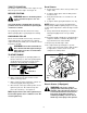
To remove shave plate, remove the carriage bolts, bell washers and hex nuts which attach it to the snow thrower housing. Reassemble new shave plate, making sure heads of the carriage bolts are to the inside of the housing. Tighten securely. Drive Pulley Auger Drive Pulley Drive Belt ENGINE Idler Pulley Refer to separate engine manual for all engine service procedures. Idler Pulley Auger Drive Belts BELT REMOVAL AND REPLACEMENT WARNING: Disconnect the spark plug wire from the spark plug and ground.
DRIVE BELT 5. Using a wrench to hold the shaft, loosen, but do not completely remove, the hex nut and bell washer on left end of gear shaft. See Figure 24. 1. Follow steps 1 through 4 of previous instructions. 2. Pull idler pulley up, and lift belt off engine pulley and friction wheel disc. See Figure 21. 3. Back out the stop bolt until the support bracket rests on the auger pulley. See Figure 23. 4. Slip belt between friction wheel and friction wheel disc. See Figure 23. Remove and replace belt.
SECTION 9: OFF-SEASON STORAGE WARNING: Never store engine with 2. Remove all dirt from exterior of engine and equipment. fuel in tank indoors or in poorly ventilated areas, where fuel fumes may reach an open flame, spark or pilot light as on a furnace, water heater, clothes dryer or other gas appliance. 3. Follow lubrication recommendations in SECTION 7: MAINTENANCE.
NOTES 16
Gear Assembly Models E600E, E610E, E640F, E660G, and E6C0F 4 17 11 9 16 13 8 15 2 14 5 10 6 3 7 12 3 1 REF. NO. 1 2 3 4 5 6 7 8 9 PART NO. 618-0123 618-0124 710-0642 711-0909 711-0910 714-0161 715-0143 717-0528 717-0526 718-0186 DESCRIPTION RH Reducer Housing LH Reducer Housing Hex Screw 1/4-20 x .75 Spiral Axle 26" Spiral Axle 28" Key Pin-Spiral Worm Gear, 20T Worm Shaft Thrust Collar REF. NO. 10 11 12 13 14 15 16 17 17 PART NO.
Blower Housing Models E600E, E610E, E640F, E660G, and E6C0F 1 2 3 4 11 10 15 18 14 5 9 12 7 8 13 32 6 31 9 18 19 20 16 22 23 38 27 10 30 34 21 28 13 25 23 13 26 30 35 41 37 36 22 18 32 31 16 43 39 40 45 40 42 39 44 18 33
REF. NO. 1 2 3 4 5 6 7 8 9 10 11 12 13 14 15 16 18 19 20 21 22 23 25 PART NO. 712-0116 756-0178 784-5632A 710-0459A 738-0281 736-0174 732-0611 712-3068 712-3010 736-0119 05931 741-0309 710-0451 705-5226 684-0040C 684-0041C 712-3010 736-0242 741-0475 784-5647 731-1379A 712-0324 736-0463 710-0703 DESCRIPTION Lock Jam Nut 3/8-24 Flat Idler Auger Idler Arm Hex Cap Screw 3/8-24 x 1.
Handle Assembly Models E600E, E610E, E640F, E660G, and E6C0F 26 65 12 57 55 ITEM #21 GOES TO GROUND WIRE OF LIGHT ASSEMBLY 4 17 67 30 42 39 29 64 55 62 40 52 20 7 43 21 14 9 12 5 66 49 42 25 45 46 36 22 26 19 38 41 23 26 56 49 1 34 12 37 12 23 59 56 6 11 18 14 23 53 52 20 61 58 43 40 54 30 43 22 31 60 25 48 23 31 45 7 48 10 2 15 9 35 8 22 32 24 46 45 25 27 31 15 23 33 45 45 16 51 28 63 44 3 25 44 20
REF. NO. 1 2 3 4 5 6 7 8 9 10 11 12 14 15 16 17 18 19 20 21 22 23 24 25 26 27 28 29 30 31 32 33 34 PART NO. 625-0007 684-0008A 684-0022 684-0036 684-0037 684-0103 710-0262 710-0276 710-0449 710-0451 710-0459 710-0599 710-1003 710-3008 710-3015 711-0653 711-0677 712-0116 712-0121 712-0271 710-0788 712-3010 712-3027 714-0104 714-0507 715-0138 720-0201A 720-0232 720-0274 720-0284 726-0100 731-0851A 731-0921 DESCRIPTION Light Ass’y, Top Mount Shift Arm Ass’y. Chute Crank Ass’y. Handle Ass’y - Engagement R.H.
Frame Assembly Models E600E, E610E, E640F, E660G, and E6C0F 27 20 37 Drive Clutch Cable 39 20 5 13 7 37 1 11 38 Auger Clutch Cable 4 6 10 3 40 4 1 2 14 26 36 15 5 16 16” Wheels 25 7 31 25 28 23 21 10 11 12 17 18 32 9 24 8 4 1 22 33 1 20 29 8 5 34 19 26 35 Blower Housing 30 1 22 1 Auger Clutch Cable
REF. NO. 1 2 3 4 5 6 7 8 9 10 11 12 13 14 15 16 17 18 19 20 PART NO. 710-1652 784-5688 784-5687A 756-0625 738-0924 684-0030 741-0563 736-0105 712-0116 741-0598 736-0188 784-5689A 710-0538 736-0242 714-0474 736-0160 710-0788 784-5590 784-5638 710-0599 DESCRIPTION Hex Screw Drive Cable Guide Bracket Auger Clutch Cable Bracket Roller Cable Hex Screw 1/4-28 Frame Assembly Ball Bearing Bell Washer Lock Jam Nut Hex Flange Bearing Flat Washer Front Support Guide Bracket Lock Hex Screw Bell Washer .340 ID x .
Engine and V-Belts IMPORTANT: For a proper working machine, use Factory Approved Parts. V-BELTS are specially designed to engage and disengage safely. A substitute (non OEM) V-Belt can be dangerous by not disengaging completely. E600E, E610E 1 2 3 5 4 8 9 11 13 10 12 27 15 16 20 16 4 22 7 6 23 14 24 18 17 19 25 REF. NO. 1 2 3 4 5 6 7 8 9 10 11 12 13 14 PART NO.
Engine and V-Belts IMPORTANT: For a proper working machine, use Factory Approved Parts. V-BELTS are specially designed to engage and disengage safely. A substitute (non OEM) V-Belt can be dangerous by not disengaging completely. E640F, E660G, E6C0F 1 2 27 3 5 4 8 9 12 11 10 16 26 19 19 16 15 16 4 16 7 6 21 22 13 14 17 25 18 23 24 REF. NO. 1 2 3 4 5 6 7 8 9 10 11 12 13 14 PART NO.
MANUFACTURER’S LIMITED WARRANTY FOR: The limited warranty set forth below is given by MTD PRODUCTS INC (“MTD”) with respect to new merchandise purchased and used in the United States, its possessions and territories. MTD warrants this product against defects in material and workmanship for a period of two (2) years commencing on the date of original purchase and will, at its option, repair or replace, free of charge, any part found to be defective in material or workmanship.