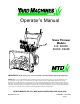
Operator’s Manual Snow Thrower Models 615, E6A5E, E645E, E665E IMPORTANT: Read safety rules and instructions carefully before operating equipment. Warning: This unit is equipped with an internal combustion engine and should not be used on or near any unimproved forestcovered, brush-covered or grass-covered land unless the engine’s exhaust system is equipped with a spark arrester meeting applicable local or state laws (if any).
TABLE OF CONTENTS Content Page Important Safe Operation Practices................................................................... 3 Contents of Hardware Pack ............................................................................... 5 Assembling Your Snow Thrower........................................................................ 6 Know Your Snow Thrower ................................................................................. 10 Operating Your Snow Thrower.............................
SECTION 1: IMPORTANT SAFE OPERATION PRACTICES This Warning symbol points out important safety instructions which, if not followed, could endanger the personal safety and/or property of yourself and others. Read and follow all instructions in this manual before attempting to operate your Snow Thrower. Failure to comply with these instructions may result in personal injury. When you see this symbol, heed its warning.
• When cleaning, repairing, or inspecting, make certain collector/impeller and all moving parts have stopped. Disconnect spark plug wire and keep away from plug to prevent accidental starting. • Use only attachments and accessories approved by the manufacturer of snow thrower (such as wheel weights, counter weights, cabs, etc.). • Never operate the snow thrower without good visibility or light. Always be sure of your footing and keep a firm hold on the handles. Walk, never run.
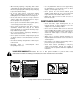
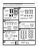
SECTION 2: CONTENTS OF HARDWARE PACK Lay out the hardware according to the illustration for identification purposes. Part numbers are shown in parentheses. (Hardware pack may contain extra items which are not used on your unit.
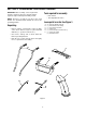
SECTION 3: ASSEMBLING YOUR SNOW THROWER Tools required for assembly IMPORTANT: After assembly, service engine with gasoline, and check oil level as instructed in the separate engine manual packed with your unit. • Pair of Pliers • Two adjustable wrenches NOTE: References to right or left side of the snow thrower are determined from behind the unit in the operating position. Loose parts in carton See Figure 1 A B C D E F Unpacking • Remove staples or break glue on the top flaps of the carton.
Assembling the handles and handle panel (hardware a and b) • • Lock Washer Raise both clutch grips. Lower left and right handles (A) down through handle panel (B) between the pivot rod and the clutch grips and attach using hardware B. See Figure 2.
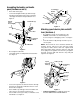
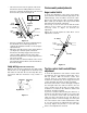
Attaching the clutch cables (hardware d) • Chute Assembly (F) Thread hex nuts onto the “Z” fittings (see insert,). Insert “Z” fitting into hole in clutch grips. See Figure 6. Hex Bolt “Z” Fitting Hex Lock Nut Hex Nut Chute Flange Keeper Figure 7 Attaching the chute directional control (hardware f) Figure 6 • • Route the left cable between engine and speed selector plate and then between handle panel and clutch lever pivot rod before threading onto the left “Z” fitting.
• Final assembly and adjustments Thread one hex nut onto the eyebolt on the chute directional control assembly until there is at least two inches of threads showing between the nut and the head of the eyebolt. See Figure 10. Cup Side Left Handle Auger control clutch To check the adjustment of the auger control clutch, push forward on the left hand clutch grip (depress the rubber bumper). There should be slack in the cable. Release the clutch grip. The cable should be straight.
NOTE: If you are uncertain that you have reached the correct adjustment, refer to the Adjustment section. Adjust skid shoes by loosening the four hex nuts and carriage bolts and moving skid shoes to desired position. Make certain the entire bottom surface of skid shoe is against the ground to avoid uneven wear on the skid shoes. Retighten nuts and bolts securely. Adjusting the skid shoes The space between the shave plate and the ground can be adjusted.
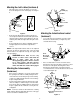
Safety ignition key Fuel cutoff valve The ignition key must be inserted in the switch before the unit will start. Remove the ignition key when snow thrower is not in use. See Figure 15. The fuel cutoff valve, located under the fuel tank, controls fuel flow from tank. Closed Open SECTION 5: OPERATING YOUR SNOW THROWER Switch Box Spark Plug When connecting the power cord, always connect cord to starter on engine first, then plug the other end into a three-hole grounded receptacle.
NOTE: Always cover vent hole in primer button when pushing. Additional priming may be necessary for first start if temperature is below 15 oF. To engage drive • • • • • Electric Start: Push starter button on top of the engine to crank the engine. When engine starts, release starter button. Recoil Start: Grasp starter handle (see Figure 15) and pull rope out slowly, until it pulls slightly harder. Let rope rewind slowly. Pull starter handle rapidly. Do not allow handle to snap back.
SECTION 6: MAKING ADJUSTMENTS WARNING: NEVER attempt to clean • chute or make any adjustments while engine is running. Chute assembly adjustment If adjustment is necessary, loosen the lock nut on the traction control cable and thread the cable in or out as necessary. Tighten the lock nut to secure the cable when correct adjustment is reached. Reassemble the frame cover. The distance snow is thrown can be controlled by adjusting the angle of the top section of the chute assembly.
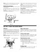
SECTION 7: MAINTAINING YOUR SNOW THROWER Auger shaft WARNING: Disconnect the spark plug wire and ground against the engine before performing any repairs or maintenance. Remove shear bolts on auger shaft. Oil or spray lubricant inside shaft. See Figure 20. Shear Bolts Engine Refer to engine manual instructions. for engine lubrication WARNING: When following instructions in separate engine manual for draining oil, be sure to protect frame to avoid oil dripping onto transmission parts.
SECTION 8: SERVICE Auger belts WARNING: Disconnect the spark plug wire and ground against the engine before performing any repairs or maintenance. • Remove the plastic belt cover on the front of the engine by removing the two self-tapping screws. See Figure 21. Engine Refer to separate engine manual for all engine maintenance procedures. Augers Self-Tapping Screws Belt Cover The augers are secured to the spiral shaft with two shear bolts and hex lock nuts. See Figure 20.
• Unhook the support bracket spring from the frame. Friction Wheel Disc NOTE: It may be necessary to loosen the six nuts that connect the frame to the auger housing to aid in belt removal. • • Lift the rear auger belt from the auger pulley, and slip belt between the support bracket and the auger pulley. See Figure 22. Repeat this step for the front auger belt. Replace both auger control belts by following instructions in reverse order.
Hex Nut Bell Washer Figure 25 SECTION 9: OFF-SEASON STORAGE Warning: Never store engine with fuel • in tank indoors or in poorly ventilated areas, where fuel fumes may reach an open flame, spark or pilot light as on a furnace, water heater, clothes dryer or other gas appliance. • • • Remove all dirt from exterior of engine and equipment. Follow lubrication recommendations in section 9. Store in a clean, dry area.
SECTION 10: TROUBLE SHOOTING GUIDE Trouble Possible Cause(s) Corrective Action Engine fails to start Fuel tank empty, or stale fuel. Fill tank with clean, fresh gasoline. Fuel will not last over thirty days unless a fuel stabilizer is used. Blocked fuel line. Clean fuel line. Choke not in ON position Move switch to ON position Faulty spark plug. Clean, adjust gap or replace. Key not in switch on engine. Insert key. Spark plug wire Connect spark plug wire. disconnected. Primer button not depressed.
SECTION 11: PARTS LIST FOR MODELS 615E THROUGH E665E 9 1 12 5 8 13 6 10 16 17 15 14 3 4 7 2 REF. NO. 1 2 3 4 5 6 7 8 PART NO. 618-0123 618-0124 710-0642 711-1020 711-0908 714-0161 715-0143 717-0526 717-0528 718-0186 11 REF. NO. 9 10 11 12 13 14 15 16 17 DESCRIPTION Housing—R.H. Housing—L.H. Hex Screw 1/4-20 x .75 Spiral Axle 22" Spiral Axle 24" Key Pin-Spiral Shaft-Worm Gear-Worm Collar-Thrust 19 PART NO.
Models 31A-615, E6A5E, E645E, and E665E 1 5 3 6 8 14 33 34 11 4 9 32 12 10 2 3 29 11 5 17 28 30 12 31 47 27 46 7 13 18 20 15 46 35 45 48 16 15 49 19 37 36 21 25 39 50 15 24 38 23 26 51 40 52 15 53 41 44 42 54 43 20 15
Models 31A-615, E6A5E, E645E, and E665E REF. NO. 1 2 3 4 5 6 7 8 9 10 11 12 13 14 15 16 17 18 19 20 21 22 23 24 25 26 27 PART NO.
Models 31A-615, E6A5E, E645E, and E665E 2 3 1 4 11 10 15 18 14 5 9 12 7 32 6 8 13 9 18 31 19 20 16 22 23 38 27 21 17 24 30 34 28 25 23 29 26 35 30 41 37 36 22 18 32 31 16 43 39 40 45 40 42 39 44 22 33
Models 31A-615, E6A5E, E645E, and E665E REF. NO. 1 2 3 4 5 6 7 8 9 10 11 12 13 14 15 16 17 18 19 20 21 22 23 24 PART NO. 712-0116 756-0178 784-5632 710-0459A 738-0281 736-0174 732-0611 712-3068 712-3010 736-0119 05931 741-0309 710-0451 705-5226 684-0052 684-0039A 712-3010 736-0119 736-0242 741-0475 784-5647 731-1379 712-0324 736-0463 710-0451 REF. NO. 25 26 27 28 29 30 31 32 33 DESCRIPTION Lock Jam Nut 3/8-24 Flat Idler Auger Idler Arm Hex Cap Screw 3/8-24 x 1.
Models 31A-615, E6A5E, E645E, and E665E 27 20 37 Drive Clutch Cable 39 20 5 13 7 38 1 11 6 10 37 Auger Clutch Cable 4 3 40 4 1 2 14 15 26 5 36 16 16” Wheels 25 13” or 15” Wheels 9 7 31 28 23 21 12 17 18 24 32 10 11 25 8 4 1 22 33 1 20 29 8 5 34 19 26 35 Blower Housing 30 1 24 1
Models 31A-615, E6A5E, E645E, and E665E REF. NO. 1 2 3 4 5 6 7 8 9 10 11 12 13 14 15 16 17 18 19 20 21 PART NO. 710-1652 784-5688 784-5687A 756-0625 738-0924 684-0030 741-0563 736-0105 712-0116 741-0598 736-0188 784-5689A 710-0538 736-0242 714-0474 736-0160 710-0788 784-5590 784-5638 710-0599 736-0351 REF. NO.
IMPORTANT: For a proper working machine, use Factory Approved Parts. V-BELTS are specially designed to engage and disengage safely. A substitute (non OEM) V-Belt can be dangerous by not disengaging completely. Model 615 1 2 3 5 4 8 9 11 13 10 12 15 16 20 22 4 16 7 6 23 14 24 18 17 19 25 REF. NO. 1 2 3 4 5 6 7 8 9 10 11 12 13 PART NO. 710-1652 731-1324 732-0339 710-0627 710-3005 05896A 748-0234 756-0985 754-0343 756-0984 736-0270 710-0230 756-0313 26 21 REF. NO.
Models E6A5E, E645E and E665E IMPORTANT: For a proper working machine, use Factory Approved Parts. V-BELTS are specially designed to engage and disengage safely. A substitute (non OEM) V-Belt can be dangerous by not disengaging completely. 1 2 27 3 5 4 8 9 12 11 10 16 26 19 19 16 15 16 4 16 7 6 21 22 13 14 17 25 18 23 20 24 REF. NO. 1 2 3 4 5 6 7 8 9 10 11 12 13 14 PART NO.
MANUFACTURER’S LIMITED WARRANTY FOR: The limited warranty set forth below is given by MTD PRODUCTS INC (“MTD”) with respect to new merchandise purchased and used in the United States, its possessions and territories. MTD warrants this product against defects in material and workmanship for a period of two (2) years commencing on the date of original purchase and will, at its option, repair or replace, free of charge, any part found to be defective in material or workmanship.