$1.00 YARD-MAN OUTDOOR PO R EQUIP " ease Spring Fall MULCHING Owner’s| rotary Ma nua ’ MOWERS Thank you for purchasing an American-built product.
IMPORTANT RULES FOR SAFE OPERATION A YOU SEE THIS SYMBOL— HEED ITS WARNING. THIS SYMBOL POINTS QUT IMPORTANT SAFETY INSTRUCTIONS WHICH, IF NOT FOLLOWED, COULD ENDANGER THE PERSONAL SAFETY AND/OR PROPERTY OF YOURSELF AND OTHERS. READ AND FOLLOW ALL INSTRUCTIONS (N THIS MANUAL BEFORE ATTEMPTING TO OPERATE YOUR LAWN MOWER. FAILURE TO COMPLY WITH THESE INSTRUCTIONS MAY RESULT IN PERSONAL INJURY.
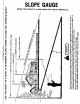
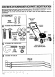
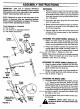
CONTENTS OF HARDWARE PACK/PARTS IDENTIFICATION Remove this shes from your owner’s manual and lay the hardware on the illustration for identification purposes. After assembly, keep the Slope Gauge which is on the reverse side of this sheet for future use. (Hardware pack may contain extra items which are not used on your unit. Part numbers are shown in parentheses.
ASSEMBLY INSTRUCTIONS IMPORTANT: This unit is shipped WITHOUT GASOLINE or OIL. After assembly, service engine with gasoline and oll as instructed in the separate engine manual packed with your unit. NOTE: Reference to right or left hand side of the mower is observed from the operating position. Refer to parts Identification on page 4 for location of parts when assembling the mower.
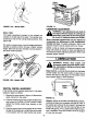
Blade Control 7 “Z" End of Brake Cable 3. Hook the “2" end of the brake cable into the hole in the blade control handle from the inside to the ~e——OUISIde as shown in figure 4. Flange on Plastic Fitting ATTACHING THE THROTTLE CABLE 1. Push the throttle control lever on the handier all the way forward to CHOKE position. See figure 5. 2. The throttle control cable is attached to the upper handle. Route the throttle control cable under the Cable lower handle and inside the handle mounting Clamp bracket.
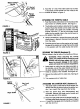
FIGURE 8. FINAL ASSEMBLY OF MOWER 1. Place hub caps in position against the inner hub of the wheel. Press firmly around the center portion of hub cap in a circular motion, similar to installing a lid on a round, plastic container, See 8, The hub caps are flexible and will snap over the 3% diameter wheal hubs. NOTE: It may be helpful to place the hub caps in hot tap water for several minutes to make them pliable before installing, especially if the temperature is less than B0°F. 2.
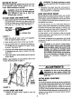
GAS AND OIL FILL-UP Service the engine with gasoline and ofl as instructed in the separate engine manual packed with your mower. Read instructions carefully. WARNING: Never fill fuel tank indoors, with engine running or unfit the engine has been allowed to cool for at least two minutes after running. 10 START ENGINE AND ENGAGE BLADE {. Dachau spark plug wire to spark plug.
FIGURE 088R Model 108R: The height adjustment handles for the wheels are located on the left side of the deck. The handles may be placed in one of nine cutting height positions. See figure 13B. For rough or uneven lawns, move the height adjustment handles to positions which will give a higher cutting height. Both front and rear handles must be placed in the same relative position. FIGURE 108R THROTTLE CONTROL ADJUSTMENT If the throttle control requires adjustment or has been replaced, adjust as follows. 1.
Engine~~Follow engine manual for lubrication instructions. Throttle—Periodically lubricate throttle control lever and throttle wire assembly with a few drops of light oil for ease of operation. MAINTENANCE WARNING: Be sure to disconnect and ground the spark plug wire before performing any repairs or maintenance. NOTE: When tipping the unfit, empty the fuel tank and keep engine spark plug side up. TROUBLE SHOOTING Refer to page 11 of this manual for trouble shooting information.
HANDLE STORAGE The handle may be placed in an upright position for storage. Move hairpin clips to outer hole on weld pins. See figure 1. Press inward on the bottom of the lower handier and push forward. The handle will lock in this position. To place the handle in the operating position, remove the starter rope from the rope guide. Grasp the lower handle at the bottom, press inward slightly and tip the handle backward. Place the hairpin clips in the inner holes.
111098R PARTS LIST FOR MODEL 0398R ROTARY MOWER el ST cue DESCRIPTION Rer) PART | cue DESCRIPTION 17310609 Control Handle Ass'y. 34 |710-1055 Hex Bolt x 17 Lg. 27100796 Truss Mach. Scr. #12 x 1.5" 736-0169 L-Wash. 3/8" LD.* 3 |731-0817A Control Pane! Haft 36 | 712-0241 Hex Nut Thd. 417310872 Throttle Control Lever 39 — Engine 57310824 Control Disc Pin 40| 777-5812 Throttle Label N | Clutch Panel Half 44 [ 735-0839 Spark Plug Boot 7 1 720-0226 Grip 45 | 753-0430 Kit—Control Housing Comp.
PARTS LIST FOR MODEL ROTARY MOWER o] TAB ) cone DESCRIPTION Mo Fast | cope DESCRIPTION 1 720-0226 Grip 58 736-0453 Bell-Wash. 47" L.D. x 1.14” 2| 731-0609 Control Handle Ass'y. 0.D. 3| 710-1205 N Rope Guide Bolt B0| 710-0561 Hex Bolt x 2.5" 4| 712-0324 Hex L-Nut %-20 Thd. 61} 736-0389 L-Wash. %" L.D.* Central Dis¢ Pin 63| 736-0119 L-Wash. 5/16" 1.D.* 6| 731-0816A Clutch Panel Half 841 682-3006 N R.H. Handle Wheel] Bret. Ass'y. 8| 710-0796 Truss Mach Scr. #12 x 1.5” Lg. | N L.H. Handle Wheel Bret. Ass'y.
TWO YEAR LIMITED WARRANTY For two years from the date of original retail purchase, Yard-man COMPANY will either repair or replace, at its option, free of charge, F.O.B. factory or authorized service firm, any part or parts round to be defective in material or workmanship. Transportation charges for the movement of any power equipment unit or attachment are the responsibility of the purchaser.