Operator's Manual 21" Self Propelled Mulching Mower Model Series 560 IMPORTANT: Read safety rules and instructions carefully before operating equipment. Warning: This unit is equipped with an internal combustion engine and should not be used on or near any unimproved forestcovered, brush-covered or grass-covered land unless the engine's exhaust system is equipped with a spark arrester meeting applicable local or state laws (if any).
TABLEOFCONTENTS Content Page 3 6 Important Safe Operation Practices Slope Gauge Assembling Your Lawn Mower Know Your Lawn Mower Content Service & Adjustments Off Season Storage 7 9 Operating Your Lawn Mower Maintaining Your Lawn Mower 10 11 Page 13 14 Trouble Shooting Illustrated Parts List 15 16 Warranty 20 FINDINGMODELNUMBER This Operator's Manual is an important part of your new lawn mower. It will help you assemble, prepare and maintain the unit for best performance.
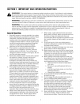
SECTION1: IMPORTANT SAFEOPERATION PRACTICES WARNING" This symbol points out important safety instructions which, if not followed, could endanger the personal safety and/or property of yourself and others. Read and follow all instructions in this manual before attempting to operate this machine. Failure to comply with these instructions may result in personal injury. When you see this symbol--HEED ITS WARNING.
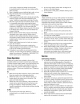
yourfooting,releasethebladecontrolhandle 2. Do not mow slopes greater than 15 degrees as immediately andthebladewillstoprotatingwithin shown on the slope gauge. threeseconds. 3. Do not mow on wet grass. Unstable footing could 9. Mowindaylightorgoodartificiallight;walk,notrun. cause slipping. 10.Stopthebladewhencrossinggraveldrives, walkwaysorroads. Children 11.
9. Neverremovegascapor addfuelwhiletheengine ishotor running.Allowenginetocoolatleasttwo minutesbeforerefueling. 10.Neveroverfillfueltank.Filltanktonomorethan½ inchbelowbottomoffillernecktoprovidespacefor fuelexpansion. 11.Replacegasolinecapandtightensecurely. 12.If gasolineisspilled,wipeitofftheengineand equipment. Moveunittoanotherarea.Wait5 minutesbeforestartingtheengine. 13.
SIGHT AND HOLD THIS LEVEL WITH A VERTICAL TREE i,II A POWER POLE A CORNER OF A BUILDING cO | 15 ° ,_ i- I.I.I WARNING Do not mow on inclines with a slope in excess of 15 degrees (a rise of approximately 2-1/2 feet every 10 feet), A riding mower could overturn and cause serious injury, If operating a walk-behind mower on such a slope, it is extremely difficult to maintain your footing and you could slip, resulting in serious injury.
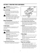
SECTION3: ASSEMBLING YOURLAWNMOWER Raise the lower handle in the direction shown in RemovingUnitFromCarton • • • • Figure 1 (step 2) till it snaps into place. Raise the upper handle in the direction shown in Figure 1 (step 3). Tighten the wing nuts which are already on the handle. See Figure 2. Remove staples, break glue on top flaps, or cut tape at carton end and peel along top flap to open. Remove loose parts included with unit (i.e., operator's manual, oil, etc.). Cut corners and lay carton down flat.
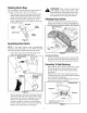
Attaching StarterRope The rope guide is already attached to the right side of the upper handle of your mower. See Figure 4. • • With spark plug wire disconnected and grounded, hold the blade control handle against the upper handle, and pull the starter rope out of the engine. Slip the rope through the rope guide as shown below. Tighten the wing nut holding the rope guide to the upper handle. \\ Starter ...... f/_-_ _ AttachingGrassCatcher • Wing Nut \ \ _,/ grass ARNING: clippings, When makeusing sur
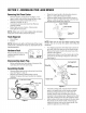
SECTION4: KNOWYOURLAWNMOWER Read this owner's manual and safety rules before operating your lawn mower. Compare the illustrations in Figure 8 with your lawn mower to familiarize yourself with the location of various controls and adjustments. Save this manual for future reference. Starter Rope The starter rope is attached to the handle. Stand behind the unit and pull the starter rope to start the unit. BladeControlHandle The blade control handle is located on the upper handle of the mower.
SECTION5: OPERATING YOURLAWNMOWER ,i1_ Recoil Starter WARNING" and understand all and instructions andRead warnings on the machine in this manual before operating. Gas& OilFill-Up • • Check oil level and add oil if necessary. Follow relevant instructions in the engine manual for this. Service the engine with gasoline as instructed in the engine manual. WARNING: Fuel Valve Use extreme care when handling gasoline. Gasoline is extremely flammable and the vapors are explosive.
For best results, do not cut wet grass because it tends to stick to the underside of the mower. For a healthy lawn, always cut off one-third or less of the total length of the grass. Lawn should be trimmed in fall as long as there is growth. ,_ For best results in mowing, keep the cutting height position high until you can determine a suitable height. BaggingGrassClippings You can use the grass catcher bag to collect clippings while you are operating the mower.
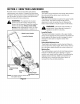
Lubrication ,_ • • WARNING: blade for sharpening When or removing replacement, the cutting protect hands by using heavy gloves or a thick rag to grasp the cutting blade. Disconnect spark plug wire from spark plug. Turn mower on its side making sure that the air filter and the carburetor are up. To RemoveBlade: • Remove the hex bolt which holds the blade adapter-pulley assembly to the engine crankshaft. See Figure 11. Remove the pulley assembly and the bell support from the crankshaft.
SECTION7: SERVICE& ADJUSTMENTS Replacing DriveBelt • Tighten the screw, loosened earlier, to secure the belt tension spring to the transmission, and reassemble the front drive cover. Remove two shoulder screws securing the front drive cover to the mower deck. See Figure 12. Right Front Wheel _ Left Front Wheel Loosen this screw Shoulder _Screw Figure 13 Replacing RearFlap • • Screw To remove rear flap, cut off the flat end of the wire rod which secures it to the deck. See Figure 14.
For rough or uneven lawns, move the height adjustment handles to higher cutting height position. \ Height Adjustment Lever Notch Lower Handle Figure 15 Reassemble the upper handle to the lower handle. Place the hairpin clips in the inner holes of the weld pins and replace the carriage bolts and wing nuts on the handle brackets. Attach the starter rope as instructed in the Assembly section.
SECTION9: TROUBLE-SHOOTING Problem Engine fails to start Possible Cause Corrective Action 1. 2. 3. 4. Blade control handle disengaged Spark plug wire disconnected Fuel tank empty, or stale fuel Blocked fuel line 1. 2. 3. 4. Engage blade control handle. Connect wire to spark plug. Fill up tank with fresh gasoline. Clean fuel line. 5. 6. Faulty spark plug Engine flooded 5. 6. Clean, adjust gap, or replace. Wait a few minutes to restart. Do not prime. 1. 2.
SECTION10: PARTSLISTFORMODELSERIES560 / 52 _14 23 25 / 79 _6 67 76 37 / IMPORTANT: For a proper working machine, use Factory Approved Parts. V-BELTS are specially designed to engage and disengage safely. A substitute (non OEM) V-Belt can be dangerous by not disengaging completely.
ModelSeries560 Ref. No Part No. Ref. No Description Part No. Description 1. 747-1214 Lower Bail Handle 43. 687-02044 Pivot Plate Assembly 2. 710-0599 TT Screw 1/4-20 x 0.5 44. 710-1257 Hex Screw 3/8-24 x 2.50 3. 736-0270 Bell Washer.265 x 0.75 45. 749-0928A Lower Handle 4. 17032A Deflector Chute Adapter 47. 720-0426 Adjustment Knob 5. 732-1014 Torsion Spring 48. 732-04089 Torsion Spring LH 6. 731-1426A Hub Cap 49. 734-2042 Wheel 8 x 2.125 7.
NOTES 18
NOTES 19
MANUFACTURER'S LIMITED WARRANTY FOR: YaRD.MaN TM ® The limited warranty set forth below is given by MTD LLC with respect to new merchandise purchased and used in the United States, its possessions and territories. e, "MTD" warrants this product against defects in material and workmanship for a period of two (2) years commencing on the date of original purchase and wilt, at its option, repair or replace, free of charge, any part found to be defective in materials or workmanship.