OPERATOR’S MANUAL Cultivator Model Number 21A-144R401 IMPORTANT: READ SAFETY RULES AND INSTRUCTIONS CAREFULLY Warning: This unit is equipped with an internal combustion engine and should not be used on or near any unimproved forestcovered, brush-covered or grass-covered land unless the engine’s exhaust system is equipped with a spark arrester meeting applicable local or state laws (if any). If a spark arrester is used, it should be maintained in effective working order by the operator.
TABLE OF CONTENTS Content Page Important Safe Operation Practices................................................................... 3 Assembling Your Cultivator................................................................................ 5 Know Your Cultivator ......................................................................................... 5 Operating Your Cultivator .................................................................................. 6 Maintaining Your Cultivator...............
SECTION 1: IMPORTANT SAFE OPERATION PRACTICES WARNING: This symbol points out important safety instructions which, if not followed, could endanger the personal safety and/or property of yourself and others. Read and follow all instructions in this manual before attempting to operate this machine. Failure to comply with these instructions may result in personal injury. When you see this symbol - heed its warning.
18. Never pick up or carry machine while the engine is running. 19. Use only attachments and accessories approved by the manufacturer. Failure to do so, can result in personal injury. 20. If situations occur which are not covered in this manual, use care and good judgment. Contact your dealer or telephone 1-800-800-7310 for assistance and the name of your nearest servicing dealer. 4. Keep bystanders, helpers, pets, and children at least 50 feet from the machine while it is in operation.
SECTION 2: ASSEMBLING YOUR CULTIVATOR • IMPORTANT: This unit is shipped without gasoline or oil in the engine. Be certain to service engine with gasoline and oil as instructed in the separate engine manual before operating your mower. • NOTE: Reference to right or left hand side of the cultivator is observed from the operating position. • Removing Unit From Carton • • • • Position the connectors aligning the marked line on the upper connector with the middle marked line on the lower connector.
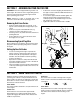
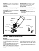
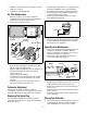
On/Off Switch Wheel Support Bracket The On/Off switch is located on the upper handle. The switch must be in the On (I) to start engine and Off (O) to stop engine. The wheel support bracket is attached to the tailpiece bracket behind the cultivator. It is used to adjust the wheels to a higher or lower resting position. Handle Connectors Edger Wheel and Blade The handle connectors are on each side between lower and upper handle. They are used to lock the upper handle in a set position.
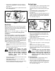
• • Starting Engine Remove the oil plug/dipstick from the crankcase and pour the entire bottle of oil into the oil fill hole. See Figure 3. Wipe up any oil that may have spilled and reinstall the oil fill plug/dipstick. • • • DipStick • Attach spark plug wire to spark plug. Make certain the metal cap on the end of the spark plug is fastened securely over the metal tip on the spark plug. Push On/Off switch on upper handle to On (I). Place choke lever in Close (A) position. See Figure 4.
• • • • With one hand grasping the starter handle, the other hand should grasp the front handle on the cultivator for a brace. Pull the starter rope briskly 3 to 5 times or until engine starts. Move choke lever to Open (C) position. With tines off the ground, depress the throttle lever against the upper handle to increase engine speed and rotate tines.
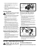
• • • • • Push the On/Off switch to Off (O) position to stop engine and tines and disconnect spark plug to avoid accidental starting. It may be necessary to lay the cultivator back in a horizontal position on a flat level surface with the upper handle touching the ground. Remove the click pin from each end of the tine shaft and slide the tines off the shaft. Slide new tines on with hubs facing out. The four tines are marked with letters A and B and an A and a B tine must be on the same side.
• • • Refill the crankcase with 3.4 fl.oz. (100 ml.) of SAE 30 SF, SG, or SH oil. Replace the oil fill plug/dipstick. • Air Filter Maintenance • • • Open the air filter cover on side of engine by pushing the tab on the left side in and swinging the air filter cover out and off. See Figure 9. Remove the air filter and screen. Stop the engine and allow it to cool. Grasp the plug wire firmly and pull the cap from the spark plug.
• • cylinder. Pull the starter rope slowly to distribute the oil and reinstall the spark plug. Wipe equipment with a oiled rag to prevent rust. Never store the unit with fuel in the tank where fumes may reach an open flame or spark. If the unit will be stored for longer than 60 days: NOTE: Remove the spark plug and drain all of the oil from the cylinder before attempting to start the unit after storage.
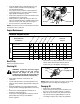
Model 21A-144R401 1 3 4 2 5 8 7 6 15 13 8 16 11 11 12 13 18 14 9 10 37 19 20 21 22 17 23 27 28 24 26 22 27 25 33 29 34 36 32 31 35 30 12
Model 21A-144R401 Ref. No. 1. 2. 3. 4. 5. 6. 7. 8. 9. 10. 11. 12. 13. 14. 15. 16. 17. 18. 19. Part No. 747-1320 732-1038 725-2009 720-0294 746-1147 749-1294A 731-1268 710-0405 725-0157 718-0812 731-1267 720-0241 736-0451 749-1295 710-0378 749-1299 712-3004A 714-0104 686-0181 Ref. No. Part Description Throttle Control Torsion Spring On/Off Switch Foam Grip Throttle Cable Upper Handle Upper Handle Connector Carriage Screw 5/16-18 x 3.
Model 21A-144R401 1 2 3 20 30 31 32 11 43 21 13 14 23 26 36 15 29 16 17 42 48 51 38 52 40 41 53 56 19 55 39 18 57 95 58 93 84 60 67 64 81 91 74 85 83 62 82 94 92 61 63 77 79 74 65 80 86 78 69 92 54 59 66 89 72 90 68 76 75 87 73 88 71 69 35 37 46 47 33 34 12 44 28 10 8 45 25 9 7 49 24 27 6 50 22 5 4 70 14
Model 21A-144R401 Ref. No. 1. 2. 3. 4. 5. 6. 7. 8. 9. 10. 11. 12. 13. 14. 15. 16. 17. 18. 19. 20. 21. 22. 23. 24. 25. 26. 27. 28. 29. 30. 31. 32. 33. 34. 35. 36. 37. 38. 39. 40. 41. 42. 43. 44. 45. 46. 47. 48. Part No.
MANUFACTURER’S LIMITED WARRANTY FOR: The limited warranty set forth below is given by MTD PRODUCTS INC (“MTD”) with respect to new merchandise purchased and used in the United States, its possessions and territories. MTD warrants this product against defects in material and workmanship for a period of two (2) years commencing on the date of original purchase and will, at its option, repair or replace, free of charge, any part found to be defective in material or workmanship.