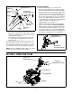
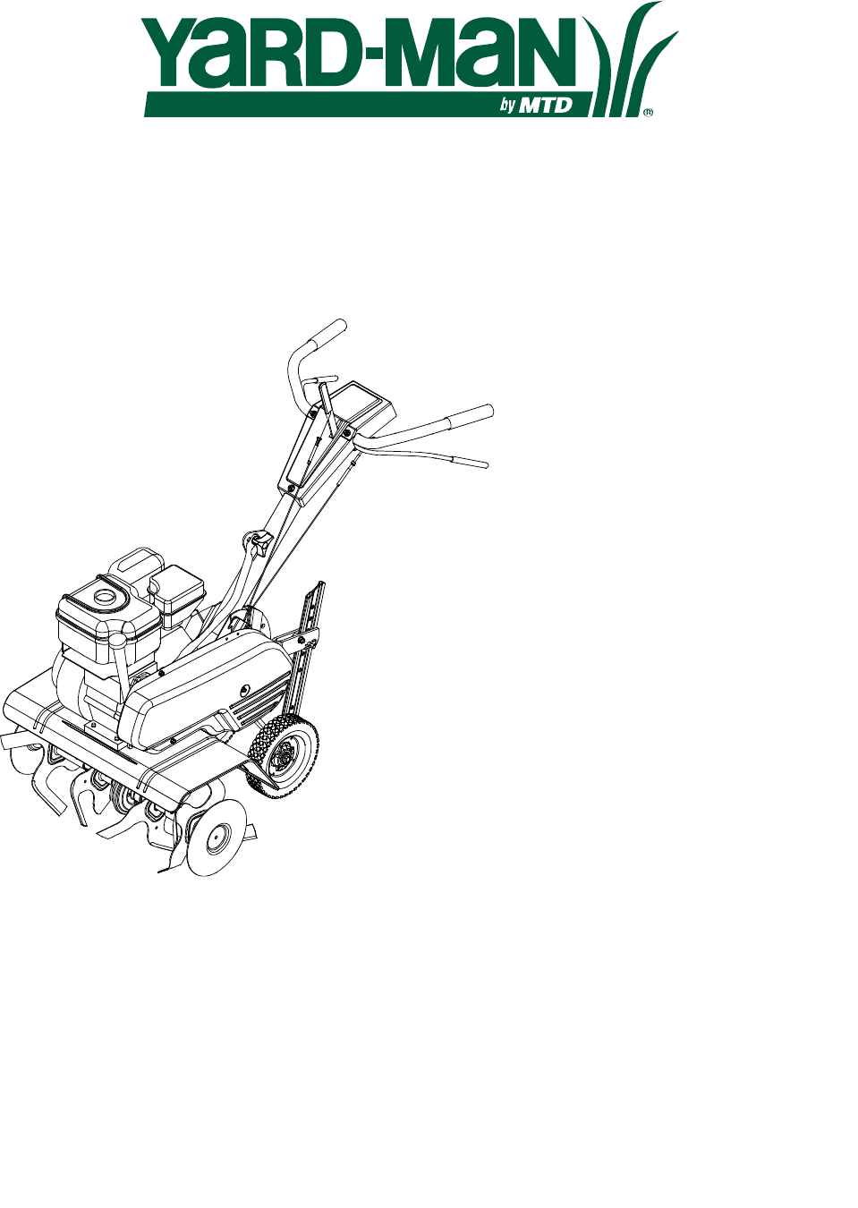
OPERATOR’S MANUAL Front Tine Tiller Model Number 21A-392B401 IMPORTANT: READ SAFETY RULES AND INSTRUCTIONS CAREFULLY Warning: This unit is equipped with an internal combustion engine and should not be used on or near any unimproved forestcovered, brush-covered or grass-covered land unless the engine’s exhaust system is equipped with a spark arrester meeting applicable local or state laws (if any). If a spark arrester is used, it should be maintained in effective working order by the operator.
TABLE OF CONTENTS Content Page Important Safe Operation Practices................................................................... 3 Assembling Your Tiller ....................................................................................... 5 Know Your Tiller................................................................................................. 6 Operating Your Tiller.......................................................................................... 7 Making Adjustments .............
SECTION 1: IMPORTANT SAFE OPERATION PRACTICES WARNING: This symbol points out important safety instructions which, if not followed, could endanger the personal safety and/or property of yourself and others. Read and follow all instructions in this manual before attempting to operate this machine. Failure to comply with these instructions may result in personal injury. When you see this symbol— heed its warning.
10. 11. 12. 13. 14. 15. 16. 17. 18. 19. 20. 21. Start the engine according to the instructions found in this manual and keep feet well away from the tines at all times. After striking a foreign object, stop the engine, disconnect the spark plug wire and ground against the engine. Thoroughly inspect the machine for any damage. Repair the damage before starting and operating. Disengage all clutch levers and stop engine before you leave the operating position (behind the handles).
SECTION 2: ASSEMBLING YOUR TILLER IMPORTANT: This unit is shipped without gasoline or oil in the engine. Be certain to service engine with gasoline and oil as instructed in the separate engine manual before operating your mower. • NOTE: Reference to right or left hand side of the tiller is observed from the operating position. Attaching The Handle Assembly • • Removing Unit From Carton • • • • • Remove staples, break glue on top flaps, or cut tape at carton end and peel along top flap to open carton.
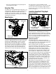
Final Clutch Adjustment Reverse Tine Engagement Lever Z End Hooked in Bracket Threaded Rod To check the clutch cables, proceed as follows: • Disconnect the spark plug wire and move it away from the spark plug to prevent accidental starting. • Engage and release the forward tine engagement handle, then the reverse tine engagement lever. If an excessive noise is heard when releasing either the tine drive clutch handle or lever, the cable may be too loose.
WARNING: Read, understand, and follow all instructions and warnings on the machine and in this manual before operating. furrow, and prepare your garden for seeding. The end caps are used to avoid tilled soil from overflowing onto unwanted areas. Handle Knob Forward Tine Engagement Handle The handle knob is attached to the handle brace and it is used to adjust the height of the handle to three different settings. The forward tine engagement handle is located beneath the tiller handle.
• Disconnect spark plug wire from spark plug and ground against the engine. The end caps are used to avoid tilled soil from overflowing onto unwanted areas. They are removable from the outer axle by removing the hairpin clip and clevis pin that secures each end cap. Slide end cap off the axle. See Figure 7. Using Your Tiller Your tiller is a precision built machine designed for seed bed preparation, cultivating, furrowing, and mulching.
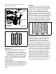
Cultivating which are turned up should be removed from the garden area. See Figure 10. For cultivating, a two to three inch depth is desirable. Setting the wheels and depth stake so that the wheels are about two inches above the ground while the tiller is resting on the tines and depth stake will allow the machine to work at cultivating depth. The throttle should be set to control forward movement to a slow walking speed. With the outer tine installed, the working width of the machine is 22 or 24 inches.
SECTION 5: MAKING ADJUSTMENTS WARNING: Disconnect the spark plug wire and ground it against the engine before performing any adjustments. clips. For cultivation, reduce the tine width to 13 inches by removing the outer tines completely. See Figure 12. Engine Adjustment Refer to the separate engine manual for engine adjustment instructions. Wheel Adjustment 22” To adjust the wheel yoke and wheel position, refer to the Operating Section.
Pivot Points Lubricate all pivot points and linkages at least once a season with light oil. Forward Belt Reverse Idler Pulley Tine Shafts Remove tine assemblies and lubricate the tine shafts at least once a season. Wheel Shafts Remove wheel assemblies and lubricate the axle shafts at least once a season. Hex Nut Cleaning Tine Area Clean the underside of the tine shield after each use. The dirt washes off the tines easier if washed off immediately instead of after it dries.
• • • Clean the exterior of engine and the entire tiller thoroughly. Lubricate the tiller as described in the lubrication instructions. We do not recommend the use of pressure washers to clean your unit. They may cause damage to electric components, spindles, pulleys, bearings or the engine. The use of pressure washers will result in shortened life and reduce serviceability. Refer to the engine manual for correct engine storage instructions. • • Wipe tines with oiled rag to prevent rust.
Notes 13
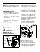
Model 392 10 9 3 11 1 4 12 2 13 6 8 5 7 14 2 16 15 30 18 17 22 19 49 21 35 29 30 27 28 26 31 32 36 20 23 37 42 38 34 37 25 33 30 40 50 24 39 41 45 51 58 30 60 43 44 46 47 61 53 48 59 55 56 57 52 54 62 55 53 14
Model 392 Ref. No. 1. 2. 3. 4. 5. 6. 7. 8. 9. 10. 11. 12. 13. 14. 15. 16. 17. 18. 19. 20. 21. 22. 23. 24. 25. 26. 27. 28. 29. 30. 31. Part No. 712-0442 736-3020 720-0270A 731-1600 710-0779A 720-0274 712-0287 726-0135 686-0083 720-0269 710-0641 731-1645A 736-0140 686-0014A 736-0264 649-0022B 710-1236 720-0195 749-1401 736-0921 710-3194 786-0005 714-0149B 712-3004A 786-0003 786-0004 711-0415 710-0805 710-0189 736-0242 711-1036A Part Description Ref. No. Acorn Lock Nut 1/4-20 Flat Washer .271” I.D. x .
Model 392 26 25 24 24 23 47 13 30 12 29 31 48 27 32 28 34 35 36 41 33 39 38 44 22 37 14 40 15 9 10 49 8 43 6 42 7 11 4 46 5 45 1 19 16 2 19 20 3 21 17 18 16
Model 392 Ref. No. 1. 2. 3. 4. 5. 6. 7. 8. 9. 10. 11. 12. 13. 14. 15. 16. 17. 18. 19. 20. 21. 22. 23. 24. Part No. 712-0392 736-3020 710-0599 711-0920 712-3004A 710-0723 756-0313 786-0149 786-0144 712-0266 786-0057 710-0599 786-0043A 710-3008 712-3004A 686-0091 686-0106 714-0149B 711-0415 642-0023 642-0024 642-0003 642-0002 746-0918 746-0953 756-0585 Part Description Ref. No. Hex L-Stop nut 1/4-28 Flat Wash. .266” I.D. x .625” O.D. Hex Washer Screw 1/4-20 x .
MANUFACTURER’S LIMITED WARRANTY FOR: The limited warranty set forth below is given by MTD LLC with respect to new merchandise purchased and used in the United States, its possessions and territories. MTD LLC warrants this product against defects for a period of two (2) years commencing on the date of original purchase and will, at its option, repair or replace, free of charge, any part found to be defective in materials or workmanship.