OPERATOR’S MANUAL Yard Vacuum Chipper/Shredder/ Vacuum/Hose Model Number 247.770380 Factory Number 24A-060F402 IMPORTANT: READ SAFETY RULES AND INSTRUCTIONS CAREFULLY Warning: This unit is equipped with an internal combustion engine and should not be used on or near any unimproved forestcovered, brush-covered or grass-covered land unless the engine’s exhaust system is equipped with a spark arrester meeting applicable local or state laws (if any).
TABLE OF CONTENTS Content Page Important Safe Operation Practices................................................................... 3 Assembling Your Yard Vacuum ......................................................................... 5 Know Your Yard Vacuum................................................................................... 7 Operating Your Yard Vacuum ............................................................................ 8 Maintaining Your Yard Vacuum .............................
SECTION 1: IMPORTANT SAFE OPERATION PRACTICES WARNING: This symbol points out important safety instructions which, if not followed, could endanger the personal safety and/or property of yourself and others. Read and follow all instructions in this manual before attempting to operate this machine. Failure to comply with these instructions may result in personal injury. When you see this symbol - heed its warning.
i. Never store the machine or fuel container inside where there is an open flame, spark, or pilot light (e.g. furnace, water heater, space heater, clothes dryer, etc.) j. To reduce a fire hazard, keep machine free of grass, leaves, or other debris build-up. Clean up oil or fuel spillage and remove any fuel soaked debris. k. Allow machine to cool at least 5 minutes before storing. 9. Never operate without either the inlet nozzle or optional hose attachment properly attached to the machine.
WARNING - YOUR RESPONSIBILITY: Restrict the use of this power machine to persons who read, understand and follow the warnings and instructions in this manual and on the machine. NOTE: Not all safety labels may apply to your Yard Vacuum. SECTION 2: ASSEMBLING YOUR YARD VACUUM IMPORTANT: This unit is shipped without gasoline or oil in the engine. Be certain to service engine with gasoline and oil as instructed in the separate engine manual before operating your machine.
Attaching The Handle • • • • • Unfold the upper handle until it aligns with the lower handle. Secure the two handles by tightening the wing nuts (carriage bolts must be seated properly into the handle). See Figure 1 Remove the hairpin clips from the handle brackets on the Yard Vacuum and remove the carriage bolts and wing nuts from the lower handle. See Figure 2. Place the bottom holes in lower handle over pins on handle brackets and secure with hairpin clips.
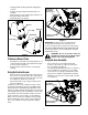
Attaching The Blower Chute • • • Blower Chute Grasp blower chute with one hand and slide locking rod on mounting bracket with other hand toward engine. Use end of mounting bracket as leverage when sliding the locking rod. See Figure 5. Slip blower chute over rim of the discharge opening and release locking rod to secure chute in place. Make sure the safety switch button is fully depressed by the front tab on the blower chute. Raise the nozzle height to the highest setting when using the blower chute.
Chipper Chute Hose Handle Allow twigs and small branches up to 1 1/2” in diameter to be fed into the impeller for chipping. Used to guide hose assembly when vacuuming. Blower Chute The nozzle/hose vac handle is located on top of the nozzle and it is used to regulate the vacuum between the nozzle and the hose assembly. Nozzle/Hose Vac Handle When attached to unit the blower chute is used to blow or scatter yard waste such as leaves, pine needles, or small twigs across yard.
• • • • Hold bag handle and bag clip while emptying the contents. Compress bag opening and fold inner flap over opening. Fold outer flap over inner flap and insert buttons on the bag through metal outlets. Twist the buttons to lock bag. Nozzle/Hose Vac Handle (Top Position) Buttons Bag Clip Inner Flap Bag Handle Spring Loaded Pin (First Hole) Outer Flap Figure 8 IMPORTANT: The flail screen is located inside the housing in the discharge area.
Nozzle Height Adjustment The nozzle can be adjusted to any six positions, ranging from 5/8” to 4 1/8” ground clearance. The nozzle height has to be adjusted according to the conditions. Move the height adjustment levers forward or backward to adjust the nozzle upwards or downwards. See Figure 10. NOTE: In general, raise the nozzle height to vacuum a thick layer of leaves or to operate with the blower chute and lower the nozzle height for smoother surfaces.
Maintenance Engine Refer to the separate engine manual for all engine maintenance instructions. • • • Check engine oil level before each use as instructed in the separate engine manual packed with your unit. Read and follow instructions carefully. Clean air cleaner every 25 hours under normal conditions or once a season. Clean every few hours under extremely dusty conditions. To service the air cleaner, refer to the separate engine manual packed with your unit.
• Housing Screws • • • • • Lower Housing Screws Nozzle Screws • NOTE: Make certain chipper blade is reassembled with the sharp edge facing upward. See Figure 16. Figure 14 • • Apply lubricant to the threads of impeller removal tool and then thread the tool into the crankshaft. Stop when the impeller assembly can move on the crankshaft. Remove the impeller assembly from the crankshaft. Unthread the impeller removal tool from the impeller assembly.
SECTION 6: TROUBLESHOOTING Problem Engine fails to start Cause Remedy 1. Spark plug wire disconnected. 2. Fuel tank empty or stale fuel. 3. Throttle control lever not in correct starting position. (If Equipped) 4. Choke not in CHOKE position. 5. Blocked fuel line. 6. Faulty spark plug. 1. Connect wire to spark plug. 2. Fill tank with clean, fresh gasoline. 3. Move throttle lever to FAST position. 1. Spark plug wire loose. 2. Unit running on CHOKE. 4. Water or dirt in fuel system. 5. Dirty air cleaner.
Model 24A-060F402 1 2 3 17 8 5 4 6 13 4 9 11 7 12 7 15 16 14 18 19 21 11 20 22 23 48 33 24 47 25 46 26 4 31 51 55 29 27 28 34 35 31 30 44 45 32 24 49 36 50 37 43 41 42 40 38 11 52 56 39 53 4 49 54 14
Model 24A-060F402 Ref. No. 1. 2. 3. 4. 5. 6. 7. 8. 9. 11. 12. 13. 14. 15. 16. 17. 18. 19. 20. 21. 22. 23. 24. 25. 26. 27. 28. 29. Part No. 720-0295 749-1423 720-0279 712-3004A 710-1205 781-1056 710-0528 720-0314 710-1174 710-0604A 681-0174 749-0907B 711-1293 710-0703 712-0397 731-1402B 725-1700 725-3166 731-1613 710-0224 629-0920 714-0104 736-0264 732-0962 781-0778A 747-1153 710-3195 710-3025 Ref. No.
Model 24A-060F402 58 1 59 2 3 60 4 5 6 7 10 8 11 12 9 14 13 16 17 15 18 56 19 15 37 23 21 26 27 22 17 24 28 41 25 30 39 29 36 44 43 31 20 38 33 32 34 40 42 46 49 45 35 51 53 42 39 57 44 47 48 50 52 54 16 55
Model 24A-060F402 Ref. No. 1. 2. 3. 4. 5. 6. 7. 8. 9. 10. 11. 12. 13. 14. 15. 16. 17. 18. 19. 20. 21. 22. 23. 24. 25. 26. 27. 28. 29. 30. 31. Part No. 664-0090 681-0154 710-1054 781-0490 681-0152 781-0735 719-0329 715-0166 711-1401 736-0247 736-0217 710-0818 710-3038 781-0721A 712-3004A 712-3027 736-0142 714-0225 711-1560 731-2520 781-1064 732-1156 726-0106 711-1551 712-0161 736-0400 731-2485 710-1156 750-1294 732-3118 732-1151 Ref. No. Part Description Bag Assembly Screen Assembly Hex Screw 5/16-24 x 1.
Notes 18
ÍNDICE Contenido Página Medidas importantes de seguridad ..................................................................................20 Montaje de la aspiradora para patios ...............................................................................22 Conozca las propiedades de la aspiradora para patios ...................................................24 Funcionamiento de la aspiradora para patios..................................................................
SECCIÓN 1: MEDIDAS IMPORTANTES DE SEGURIDAD ADVERTENCIA: La presencia de este símbolo indica que se trata de instrucciones importantes de seguridad que debe respetar para evitar poner en riesgo su seguridad personal y / o material y de otras personas. Lea y siga todas las instrucciones contenidas en este manual antes de intentar poner esta máquina en funcionamiento. De no hacerlo puede ocasionar lesiones. Cuando encuentre este símbolo - respete la advertencia que aparece a continuación del mismo.
k. aceite o combustible y saque todos los escombros embebidos con combustible. Deje que la máquina se enfríe por lo menos 5 minutos antes de guardarla. 11. Nunca opere esta máquina sin buena visibilidad o iluminación. Siempre debe estar seguro de que está bien afirmado y sostenga bien las manijas. 12. No opere esta máquina en superficies con grava. 13. No opere esta máquina estando bajo los efectos del alcohol o de drogas. 14. El silenciador y el motor se calientan y producen una quemadura. No los toque.
SECCIÓN 2: MONTAJE DE LA ASPIRADORA PARA PATIOS IMPORTANTE: Esta unidad se envía sin gasolina ni aceite en el motor. Antes de operar la máquina cargue el motor con gasolina y aceite como se indica en el manual separado del mismo. Canal de soplado Superior Manija NOTA: Las referencias a los lados derecho o izquierdo de la aspiradora para patios se hacen observando la máquina desde la posición de operación.
Montaje de la manija • • • • • Despliegue la manija superior hasta que quede alineada con la manija inferior. Para sujetar las dos manijas ajuste las tuercas de mariposa (los pernos del carro deben estar colocados de forma adecuada en la manija). Ver Figura 1 Saque los broches de horquilla de los soportes de la manija de la aspiradora para patios y saque los pernos del carro y las tuercas de mariposa de la manija inferior. Ver Figura 2.
Instalación del canal de soplado • • • De soplado Canal Tome el canal de soplado con una mano y deslice la varilla de seguridad del soporte de montaje hacia el motor con la otra mano. Use el extremo del soporte de montaje como palanca cuando deslice la varilla de seguridad. Ver Figura 5. Deslice el canal de soplado por encima del borde de la abertura de descarga y suelte la varilla de seguridad para ajustar el canal en su lugar.
Canal de la cortadora Manija de la manguera Permita que las ramas pequeñas de hasta 1 1/2” de diámetro ingresen al motor para picarlas. Se utiliza para guiar el montaje de la manguera mientras se aspira. Canal de soplado Manija del pico / manguera de la aspiradora Cuando se lo une a la unidad el canal de soplado se utiliza para soplar o esparcir por los patios los desechos que se acumulan en los mismos como por ejemplo las hojas, las agujas de los pinos o las ramas pequeñas.
• • • • • Gire los dos botones de la parte posterior de la bolsa para abrirla y vaciar el contenido. Ver Figura 7. Sostenga la manija y el broche de la bolsa mientras vacía el contenido. Comprima la abertura de la bolsa y doble la aleta interior sobre la abertura. Doble la aleta exterior sobre la aleta interior e inserte los botones de la bolsa a través de las salidas metálicas. Gire los botones para cerrar la bolsa. hasta 1 1/2” de diámetro en el canal de la cortadora.
Ajuste de la altura del pico Puede ajustar el pico en seis posiciones que varían desde 5/ 8” a 4 1/8” de distancia del suelo. Debe ajustar la altura del pico según las condiciones. Mueva las palancas para ajustar la altura hacia adelante o hacia atrás para ajustar el pico hacia arriba o hacia abajo. Ver Figura 10. NOTA: En general, levante la altura del pico para aspirar una capa gruesa de hojas o para usar el canal de soplado y baje la altura del pico para las superficies más lisas.
• • • Controle el nivel de aceite del motor antes de cada uso como se indica en el manual separado del mismo que viene embalado con la unidad. Lea y siga las instrucciones cuidadosamente. Limpie el depurador de aire cada 25 horas en condiciones normales o una vez por temporada. Limpie a intervalos de pocas horas cuando haya mucho polvo. Para realizar el control del depurador de aire consulte el manual separado del motor que viene embalado con la unidad.
• Caja Tornillos • • • • • Pico Tornillos • Caja inferior Tornillos Figura 14 • • Aplique lubricante a las roscas de la herramienta que se usa para sacar el motor y luego enrosque la herramienta en el cigüeñal. Deténgase cuando el montaje del motor se pueda mover en el cigüeñal. Saque el montaje del motor del cigüeñal. Desenrosque del montaje del motor la herramienta que se utiliza para sacarlo.
SECCIÓN 6: GUÍA PARA LA SOLUCIÓN DE PROBLEMAS Problema El motor no arranca Causa 1. 2. Se ha desconectado el cable de la bujía. El tanque de combustible está vacío o el combustible es viejo. La palanca de control del regulador no está en la posición de arranque correcta. (Si está incluida) La palanca de obturación no está en la posición CHOKE (obturación). La línea del combustible está bloqueada. La bujía no funciona correctamente. 1. 2. 3. Conecte el cable a la bujía.
GARANTÍA LIMITADA DEL FABRICANTE PARA: La garantía limitada que se extiende a continuación es otorgada por la empresa MTD PRODUCTS INC (“MTD”) con respecto a mercaderías nuevas compradas y utilizadas en los Estados Unidos, sus posesiones y territorios.
MANUFACTURER’S LIMITED WARRANTY FOR: The limited warranty set forth below is given by MTD PRODUCTS INC (“MTD”) with respect to new merchandise purchased and used in the United States, its possessions and territories. MTD warrants this product against defects in material and workmanship for a period of two (2) years commencing on the date of original purchase and will, at its option, repair or replace, free of charge, any part found to be defective in material or workmanship.