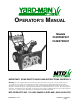
OPERATOR’S MANUAL Models 31AE553F401 31AE573H401 IMPORTANT: READ SAFETY RULES AND INSTRUCTIONS CAREFULLY Warning: This unit is equipped with an internal combustion engine and should not be used on or near any unimproved forestcovered, brush-covered or grass-covered land unless the engine’s exhaust system is equipped with a spark arrester meeting applicable local or state laws (if any). If a spark arrester is used, it should be maintained in effective working order by the operator.
SECTION 1: IMPORTANT SAFE OPERATION PRACTICES WARNING: THIS SYMBOL POINTS OUT IMPORTANT SAFETY INSTRUCTIONS WHICH, IF NOT FOLLOWED, COULD ENDANGER THE PERSONAL SAFETY AND/OR PROPERTY OF YOURSELF AND OTHERS. READ AND FOLLOW ALL INSTRUCTIONS IN THIS MANUAL BEFORE ATTEMPTING TO OPERATE YOUR SNOW THROWER. FAILURE TO COMPLY WITH THESE INSTRUCTIONS MAY RESULT IN PERSONAL INJURY. WHEN YOU SEE THIS SYMBOLHEED ITS WARNING.
repairs, adjustments, or inspections. Never place your hand in the discharge or collector openings. Use a stick or wooden broom handle to unclog the discharge opening. • Never direct discharge at bystanders or allow anyone in front of unit. • Take all possible precautions when leaving the unit unattended. Disengage the collector/impeller, shift into neutral, stop the engine, and remove the key.
SECTION 2: FINDING SNOW THROWER MODEL NUMBER This Operators Manual is an important part of your new snow thrower. It will help you assemble, prepare and maintain your snow thrower. Please read and understand what it says. Before you prepare your snow thrower for its first use, please locate the model plate and copy the information from it in this Operators Manual. The information on the model plate is very important if you need help from your dealer or the MTD Customer Support Department.
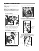
SECTION 5: SET-UP INSTRUCTIONS NOTE: Reference to right or left side of the snow sure all cables are aligned with cable roller guides. See Figure 3. thrower in this manual is from behind the unit in the operating position. IMPORTANT: Check the adjustments as instructed on page 6, and make any final adjustments necessary before operating your snow thrower. Failure to follow the instructions may cause damage to the snow thrower and void warranty. 1.
12. Adjust the eyebolt on the chute crank so the chute crank does not touch the engine. Move the hex nut against the handle (if necessary). Tighten the wing nut to secure the crank in this position. 13. If not already attached, slip the cables that run from the handle panel to the chute into the cable guide on top of the engine. See Figure 8. NOTE: If the connector is not properly assembled, the shift rod will pivot and you will not be able to shift gears or change directions. 7.
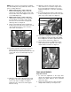
on the traction drive cable and thread the cable in one turn. 9. Recheck the adjustment and repeat adjustment as necessary. Tighten the lock nut to secure the cable when correct adjustment is reached. auger drive clutch grip against the left handle completely. 3. If necessary, loosen the hex lock nut and thread the cable in (for less slack) or out (for more slack) as necessary. Recheck the adjustment. Tighten the lock nut against the cable when correct adjustment is reached.
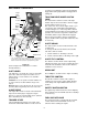
SECTION 6: CONTROLS steering your snowthrower. Squeeze the right turn trigger when turning right and the left trigger when turning left. Auger Drive Clutch TRACTION DRIVE/AUGER CLUTCH LOCK Throttle Control The traction drive clutch is located on the right handle. Squeeze the traction drive clutch to engage the wheel drive. Release to stop. This same lever also locks the auger clutch so you can turn the chute crank without interrupting the snow throwing process.
SECTION 7: OPERATION GAS AND OIL FILL-UP 6. Rotate choke knob to OFF position. 7. Push the primer button while covering the vent hole. Remove finger from the primer between primes. Do not prime to start a warm engine. Prime two to three times at temperature above 15 degree F and four times below 15 degree F. 8. Connect power cord to switch box on engine. Plug the other end of power cord into a threehole, grounded 120 volt AC receptacle. 9. Push starter button to crank the engine.
2. To avoid possible freeze-up of starter, proceed as follows. Electric Starter: Connect power cord to switch box on engine, then to 120 volt AC receptacle. With the engine running, push starter button and spin the starter for several seconds. The unusual sound made by spinning the starter will not harm engine or starter. Disconnect the power cord from receptacle first, and then from switch box.
SECTION 8: ADJUSTMENTS necessary. See Figure 12. Tighten the jam nut to secure the cable when correct adjustment is reached. Reassemble the frame cover. NOTE: If you placed plastic under the gas cap, be certain to remove it. WARNING: Never attempt to clean chute or make any adjustments while engine is running. CHUTE ASSEMBLY The distance snow is thrown can be adjusted by adjusting the angle of the chute assembly. Refer to the Control section of this manual.
SECTION 9: LUBRICATION GEAR BOX (See Figure 13) WARNING: Disconnect the spark plug wire and ground against the engine before performing any lubrication or maintenance. The worm gear box has been filled with grease at the factory. If disassembled for any reason, lubricate with 1.5 ounces of Shell Alvania grease EPR00 (part number 737-0168). Before reassembling, remove old sealant and apply Loctite 5699 or equivalent. WHEELS Oil or spray lubricant into wheel bearings at least once a season.
SECTION 10: MAINTENANCE 2. Reassemble new skid shoes with the four carriage bolts, belleville washers (cupped side goes against skid shoes) and hex nuts. Make certain the skid shoes are adjusted to be level. 3. To remove shave plate, remove the skid shoe and the rest of hardware including carriage bolts, belleville washers and hex nuts which attach shave plate to the snow thrower housing. For location of shave plate, see Figure 14. 4.
auger drive belt from the front auger pulley. WARNING: Do not attempt to change the auger belt without the help of an assistant. It is very important that one person, standing at the operating position, firmly hold the snow thrower housing to prevent it from tipping while the other person replaces the belt. Failure to comply with this may result in injury. Shift auger idler pulley Belt Brake Lock Washer, Hex Nut Align studs with holes on Frame Assembly Figure 20 7.
Drive Belt 1. Drain the gasoline from the snow thrower, or place a piece of plastic under the gas cap. 2. Remove the plastic belt cover on the front of the engine by removing the two self-tapping screws. 3. Tip the snow thrower up and forward, so that it rests on the housing. 4. Remove six self-tapping screws from the frame cover underneath the snow thrower. 5. Pull the idler pulley away from the drive belt and remove the belt from the engine pulley.
toward the friction wheel when sliding the sprocket on to the hex shaft. See Figure 26. the friction wheel assembly and hold assembly in position. See Figure 25. Shift Arm Assembly Pin Sprocket Spacer Sprocket Spacer Hex Shaft Hex Hub of Sprocket Friction Wheel Figure 26 13. Align the hex shaft with the right hand bearing and carefully guide the left hand bearing into the left side of the housing. 14. Reassemble the drive cover with the four screws that were earlier removed.
SECTION 12: TROUBLE SHOOTING GUIDE Trouble Possible Cause(s) Corrective Action Engine fails to start Fuel tank empty, or stale fuel. Fill tank with clean, fresh gasoline. Fuel will not last over thirty days unless a fuel stabilizer is used. Clean fuel line. Blocked fuel line. Move switch to ON position Choke not in ON position Clean, adjust gap or replace. Faulty spark plug. Key not in switch on engine. Insert key. Connect spark plug wire. Spark plug wire disconnected. Primer button not depressed.
SECTION 13: REPAIR PARTS 32 34 11 7 27 26 2 1 20 4 29 22 19 20 15 8 16 15 24 15 12 25 30 3 20 21 5 35 24 9 14 18 40 26 6 43 25 24 12 17 42 24 41 15 23 31 13 36 38 39 31 23 28 33 10 37 NOTE: For painted parts, please refer to the list of color codes below. Please add the applicable color code, wherever needed, to the part number to order a replacement part.
Ref. No. 1. 2. Part No. 3. 4. 5. 05931 684-0040B 684-0055A 684-0065 705-5226 710-0260 6. 710-0451 7. 710-0459A 8. 710-0604 9. 710-0703 10. 11. 12. 13. 14. 15. 16. 17. 18. 19. 20. 21. 710-0890A 712-0116 712-0324 712-0429 712-0798 712-3010 712-3068 715-0114 731-1379 732-0611 736-0119 736-0169 Code Ref. No. Description Bearing Housing Auger Housing Assy. 26” Auger Housing Assy. 30” Impeller Assy. 12” dia. Chute Reinforcement Carriage Bolt 5/16-18 x .62” Carriage Bolt 5/16-18 x .75” Gr.
NOTE: For painted parts, please refer to the list of color codes below. Please add the applicable color code, wherever needed, to the part number to order a replacement part. For instance, if a part, numbered 700-xxxx, is painted yard-man green, the part number to order would be 700-xxxx-0665.
Ref. No. Part No. 1. 2. 3. 618-0043 618-0044 618-0303A 4. 5. 6. 7. 656-0012A 684-0014B 684-0042B 684-0130 8. 9. 684-0131 710-0599 10. 710-0788 11. 710-1652 12. 13. 14. 15. 16. 17. 18. 19. 20. 21. 23 24. 25. 26. 27. 28. 29. 711-1267 711-1268 711-1364 712-0711 712-3017 713-0233 713-0374 713-0413 713-0472 714-0104 714-0474 716-0102 721-0263 732-0209 732-0264 736-0105 736-0160 Description Ref. No. Dogg Assembly: RH Dogg Assembly: LH Shift Assembly: Steerable Drive Friction Wheel Disc Assy.
6 13 4 16 11 10 6 12 17 10 1 14 4 3 15 7 2 12 6 9 8 Ref. No. Part No. 1. 710-0262 2. 710-0451 3. 710-0805 4. 710-0896 5. 6. 7. 8. 9. 10. 11. 12. 13. 14. 710-3015 712-0429 712-3027 731-0851A 731-1300A 731-1313B 731-1320 736-0159 736-0506 746-0896 15. 746-0901 16. 17. 784-5594 784-5604 5 22 Code Description Carriage Bolt: 5/16-18 x 1.5” Carriage Bolt: 5/16-18 x 0.75” Hex Bolt: 5/16-18 x 1.5 Gr. 5 Hex Washer Head AB Screw: 1/4-14 x 0.625” Hex Bolt: 1/4-20 x 0.
7 16 21 6 3 17 3 4 10 20 23 18 13 14 16 8 19 3 11 7 22 7 14 15 1 13 9 12 5 For reference only 6 11 2 15 Ref. No. 1. 2. 3. For reference only 4. 5. 6. 7. 8. 9. 10. 11. 12. 13. 14. 15. 16. 17. 18. 19. 20. NOTE: For painted parts, please refer to the list of color codes below. Please add the applicable color code, wherever needed, to the part number to order a replacement part.
37 34 40 41 35 42 43 39 30 36 A 4 38 9 21 A 13 14 23 22 11 31 19 5 10 3 17 26 29 33 16 18 24 25 15 14 28 21 6 16 1 27 32 2 12 23 8 NOTE: For painted parts, please refer to the list of color codes below. Please add the applicable color code, wherever needed, to the part number to order a replacement part. For instance, if a part, numbered 700-xxxx, is painted yard-man green, the part number to order would be 700-xxxx-0665.
Ref. No. Part No. 1. 2. 3. 4. 5. 684-0008A 684-0053 705-5266 710-0262 710-0449 6. 710-0788 7. 8. 710-0890A 710-3008 9. 10. 11. 12. 13. 14. 15. 16. 17. 18. 19. 20. 21. 22. 710-3015 711-0677 712-0287 712-0429 712-3010 714-0104 714-0145 715-0138 720-0201A 720-0284 726-0100 736-0185 736-0242 736-0270 Code Description Ref. No. Shift Arm Assembly Chute Crank Assembly Chute Crank Bracket Carr. Bolt 5/16-18 x 1.5 Carr. Screw 5/16-18 x 2.25 Gr.5 Hex Washer Head TT Screw 1/4-20 x 1.
IMPORTANT: For a properly working machine, use Factory Approved Parts. 7 V-Belts are specially designed to engage and disengage safely. A substitute (non-OEM) V-Belt can be dangerous by not disengaging completely. 10 NOTE: For painted parts, please refer to the list of color codes below. Please add the applicable color code, wherever needed, to the part number to order a replacement part.
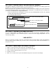
Optional Parts: Following optional parts are available for your snow thrower. Please call 1-800-800-7310 to order these parts. While ordering, do not forget to mention the applicable part number. Tire Chain: Part Number Wheel Size (with Sno Hog Tire) 16” x 6.5” 16” x 4.8” Wheel Size Tire Chain Part Number (without Sno Hog Tire) OEM-390-655 16” x 6.
MANUFACTURER’S LIMITED WARRANTY FOR: For TWO YEARS from the date of retail purchase within the United States of America, its possessions and territories, MTD PRODUCTS INC will, at its option, repair or replace, for the original purchaser, free of charge, any part or parts found to be defective in material or workmanship.