OPERATOR’S MANUAL 33” Snow Thrower Model 31AE993I401 IMPORTANT: READ SAFETY RULES AND INSTRUCTIONS CAREFULLY Warning: This unit is equipped with an internal combustion engine and should not be used on or near any unimproved forestcovered, brush-covered or grass-covered land unless the engine’s exhaust system is equipped with a spark arrester meeting applicable local or state laws (if any). If a spark arrester is used, it should be maintained in effective working order by the operator.
TABLE OF CONTENTS Content Page Important Safe Operation Practices................................................................... 3 Assembling Your Snow Thrower ....................................................................... 5 Knowing Your Snow Thrower ............................................................................ 7 Operating Your Snow Thrower .......................................................................... 9 Making Adjustments ...........................................
SECTION 1: IMPORTANT SAFE OPERATION PRACTICES This symbol points out important safety instructions which, if not followed, could endanger the personal safety and/or property of yourself and others. Read and follow all instructions in this manual before attempting to operate this machine. Failure to comply with these instructions may result in personal injury. When you see this symbol—heed its warning.
5. 6. 7. 8. 9. 10. 11. 12. 13. 14. 15. 16. 17. 18. 19. 20. Maintenance And Storage Never run an engine indoors or in a poorly ventilated area. Engine exhaust contains carbon monoxide, an odorless and deadly gas. Do not operate machine while under the influence of alcohol or drugs. Muffler and engine become hot and can cause a burn. Do not touch. Exercise extreme caution when operating on or crossing gravel surfaces. Stay alert for hidden hazards or traffic.
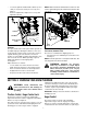
SECTION 2: ASSEMBLING YOUR SNOW THROWER NOTE: Any reference in this manual to the left or right side of the snow thrower is observed from the operator’s position. Upper Handle Unpacking • • • • • Steering Cable Remove staples from the top, sides, and ends of the shipping crate. Set panels aside to avoid tire punctures or personal injury. Remove and discard plastic bag that covers unit. Roll the unit out of the crate. Check the crate thoroughly for loose parts before discarding.
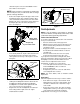
shift rod. Tap the connector until it locks over the lower shift rod. See Figure 2. Alternator Lead NOTE: If the connector is not properly assembled, the shift rod will pivot and you will not be able to change speeds or change directions. • Alternator Lead Remove the hairpin clip from the upper chute crank and slide the upper chute crank through the upper chute crank bracket and into the lower chute crank.
• • Loosen the jam nut and thread the cable in (for less slack) or out (for more slack) as necessary. See Figure 7. Recheck adjustment; readjust as necessary and tighten the jam nut. NOTE: Make certain the entire bottom surface of skid shoe is against the ground to avoid uneven wear on the skid shoes.
Shift Lever • The shift lever is located in the center of the handle panel and is used to determine ground speed and direction of travel. It can be moved into any of eight positions. See Figure 9. Chute Tilt Control Operate the snow thrower in open areas until becoming familiar with these controls. The distance snow is thrown can be changed by adjusting the angle of the chute assembly. Move the chute tilt control forward to decrease the distance, toward the rear to increase. See Figure 9.
SECTION 4: OPERATING YOUR SNOW THROWER Before Starting WARNING: The electric starter is equipped with a grounded three-wire power cord and plug and is designed to operate on 120 volt AC household current. It must be used with a properly grounded three-prong receptacle at all times to avoid the possibility of electric shock. Follow all instructions carefully prior to operating the electric starter.
To Stop Engine • • • Run engine for a few minutes before stopping to help dry off any moisture on the engine. To help prevent possible freeze-up of starter, proceed as follows. IMPORTANT: NEVER move the shift lever without first releasing the traction control. Doing so will cause premature wear to the drive system’s friction wheel. Electric Starter: • Connect power cord to switch box on engine, then to 120 volt AC receptacle.
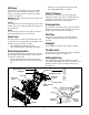
Trigger Cables Shift Arm Drive Actuator Bracket • Auger Actuator Bracket • Hex Nut And Cupped Washer necessary until the ferrule lines up with the upper hole in the shift lever. See Figure 11. Insert ferrule from the left side of the snow thrower into the upper hole. Reinstall the hairpin clip and the washer. IMPORTANT: Make certain to check for correct adjustment of the shift rod as instructed under Final Adjustments in the Assembly Section, before operating the snow thrower.
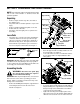
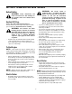
SECTION 6: MAINTAINING YOUR SNOW THROWER WARNING: Before lubricating, repair- Vent Plug ing, or inspecting, disengage all clutch levers and stop engine. Wait until all moving parts have come to a complete stop. Disconnect the spark plug wire and ground it against the engine to prevent unintended starting. Shear Bolts General Recommendations • • • • • • Always observe safety rules when performing any maintenance.
IMPORTANT: Do not overfill the gear case, since damage to the seals could result. Be sure the vent plug is free of grease in order to relieve pressure. Check V-Belts Auger Bearings and Shaft • Every season lubricate the auger bearings and the bearings on the side of the frame with light oil. See to Figure 12. • Follow the instructions below to check the condition of the drive belts every 50 hours of operation. • Use oil or spray lubricant into the bearings at the wheels at least once a season.
Shear Bolts Washer Hairpin Clip Flat Washers Belt Cover Bolts(3) Belt Cover Carriage Bolt Shave Plate Hex Nut Figure 15 • • • • • Shoulder Bolt (do not remove) Remove the six carriage bolts (three per side), belleville washers and hex nuts which attach slide shoes to the snow thrower on two sides. See Figure 8. Reassemble new slide shoes with the hardware removed earlier (cupped side of belleville washer against the slide shoes). Make certain the slide shoes are adjusted to be level.
• • • • Pull the brake bracket assembly towards the cable guide roller and unhook the auger cable “Z” fitting. Remove the upper bolts and lock washers which attach the auger housing assembly to the frame assembly using a 9/16” wrench. See Figure 16. Separate the auger housing from the frame assembly by tilting the housing forward and pulling up the handles. Using a 1/2” wrench, remove the hex screw and belleville washer from the center of the pulley on the auger housing.
• Shift Arm Assembly Shift Arm Assembly Pin Sprocket Spacer Sprocket • Spacer • Pin Insert the pin from the shift arm assembly into the friction wheel assembly and hold assembly in position. See Figure 20. Slide the hex shaft through the left side of the housing and through the friction wheel assembly. Insert the hex shaft through the sprocket and the spacer. Make certain that the chain engages both the large and the small sprocket.
SECTION 9: TROUBLESHOOTING Problem Cause Remedy Engine fails to start. 1. 2. 3. 4. 5. 6. 7. Fuel tank empty, or stale fuel. Blocked fuel line. Choke not in ON position Faulty spark plug. Safety key not in ignition switch on engine. Spark plug wire disconnected. Primer button not being used properly. 1. 2. 3. 4. 5. 6. 7. Fill tank with fresh gasoline. Clean the fuel line. Move switch to ON position Clean, adjust gap or replace. Insert the key fully into the switch. Connect spark plug wire.
Model 31AE993I401 47 8 43 8 25 16 14 21 40 31 25 42 8 7 14 21 5 1 25 55 25 27 13 17 45 18 14 48 3 26 34 54 56 53 9 50 14 51 34 26 32 13 44 25 52 46 22 5 13 49 33 41 25 14 5 11 2 35 28 6 12 15 36 37 38 29 20 24 13 29 30 10 4 23 39 25 18 19 13
Model 31AE993I401 Ref. No. 1. 2. 3. 4. 5. 6. 7. 8. 9. 10. 11. 12. 13. 14. 15. 16. 17. 18. 19. 20. 21. 22. 23. 24. 25. 26. 27. 28. Part No. 05244A 618-0281A 684-0090A 710-0371 710-0451 710-0459A 710-0528 710-0604A 710-0891 711-0640 711-0677 712-0116 712-0429 712-3010 714-0104 714-0126 714-0135 715-0118 731-1696 732-0858 736-0119 736-0159 736-0169 736-0174 736-0242 736-0250 736-0271 736-3008 Ref. No.
Model 31AE993I401 18 12 63 78 8 17 76 79 9 18 50 26 16 11 62 77 66 49 41 15 48 61 4 19 56 45 35 30 65 47 55 33 22 56 38 42 34 67 27 75 6 14 55 22 57 40 46 20 46 2 13 46 21 29 13 68 46 60 7 51 31 43 19 55 37 61 48 27 58 47 52 70 62 50 26 71 64 29 66 55 51 20 43 3 23 33 10 45 39 60 44 28 24 35 32 1 16 36 45 18 55 42 5 54 31 47 73 45 55 53 69 56 30 31 59 31 18 18 79 20 78 15 77
Model 31AE993I401 Ref. No. 1. 2. 3. 4. 5. 6. 7. 8. 9. 10. 11. 12. 13. 14. 15. 16. 17. 18. 19. 20. 21. 22. 23. 24. 25. 26. 27. 28. 29. 30. 31. 32. 33. 34. 35. 36. 37. 38. 39. 40. Part No.
Model 31AE993I401 36 37 39 35 33 A 32 A 9 22 11 6 42 38 11 40 29 34 7 24 28 A 13 9 21 32 18 6 31 A 15 35 33 1 17 19 16 21 26 4 19 43 41 22 3 21 13 10 1 15 23 27 5 44 7 23 25 30 19 5 15 19 4 34 8 2 12 20 15 22 14
Model 31AE993I401 Ref. No. 1. 2. 3. 4. 5. 6. 7. 8. 9. 10. 11. 12. 13. 14. 15. 16. 17. 18. 19. 20. 21. 22. 23. 24. 25. 26. 27. Part No. 646-0012 684-0053B 705-5266 710-3119 710-1878 710-0458 710-0572 710-0891 710-3015 711-0677 712-0287 712-0429 712-3010 714-0101 714-0104 720-0201A 720-0284 726-0100 736-0105 736-0185 736-0242 736-0270 736-0275 741-0475 747-0624 747-0983 747-0997 Ref. No. Part Description Cable Assembly: Auger/Drive Chute Crank Assembly Chute Crank Bracket Hex Screw 3/8-16 x .
Model 31AE993I401 23 6 10 15 24 26 25 15 6 14 22 18 12 8 14 7 9 4 21 1 3 11 13 13 5 17 2 19 3 20 Ref. No. 1. 2. 3. 4. 5. 6. 7. 8. 9. 10. 11. 12. 13. 14. 15. 17. 18. 19. 20. 21. 22. 23. 24. 25. 26. 24 Part No.
Model 31AE993I401 26 34 33 Ref. No. 22 29 35 22 25 30 6 23 38 12 36 27 37 22 34 26 26 32 20 24 28 31 30 4 6 33 15 21 6 19 3 10 16 17 6 18 10 8 14 13 2 6 4 11 1 7 9 5 25 Part No. Description 1. 710-0276 Carriage Screw 2. 710-0458 Carriage Bolt 5/16-18 x 1.75” 3. 710-0805 Hex Bolt 5/16-18 x 1.5” 4. 710-0896 Hex AB Screw 1/4-14 x .625” 5. 710-3015 Hex Screw 1/4-20 x .75” 6. 712-0429 Hex Lock Nut 7. 712-3027 Hex Flange Lock Nut 8. 731-0846C Upper Chute 9.
Notes 26
MANUFACTURER’S LIMITED WARRANTY FOR: c. Routine maintenance items such as lubricants, filters, blade sharpening and tune-ups, or adjustments such as brake adjustments, clutch adjustments or deck adjustments; and normal deterioration of the exterior finish due to use or exposure. d. MTD does not extend any warranty for products sold or exported outside of the United States of America, its possessions and territories, except those sold through MTD’s authorized channels of export distribution.