OPERATOR’S MANUAL 45” Snow Thrower Model 31AE993J401 IMPORTANT: READ SAFETY RULES AND INSTRUCTIONS CAREFULLY Warning: This unit is equipped with an internal combustion engine and should not be used on or near any unimproved forestcovered, brush-covered or grass-covered land unless the engine’s exhaust system is equipped with a spark arrester meeting applicable local or state laws (if any). If a spark arrester is used, it should be maintained in effective working order by the operator.
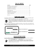
TABLE OF CONTENTS Content Page Important Safe Operation Practices................................................................... 3 Assembling Your Snow Thrower ....................................................................... 5 Knowing Your Snow Thrower ............................................................................ 7 Operating Your Snow Thrower .......................................................................... 9 Making Adjustments ...........................................
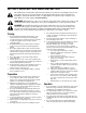
SECTION 1: IMPORTANT SAFE OPERATION PRACTICES This symbol points out important safety instructions which, if not followed, could endanger the personal safety and/or property of yourself and others. Read and follow all instructions in this manual before attempting to operate this machine. Failure to comply with these instructions may result in personal injury. When you see this symbol—heed its warning.
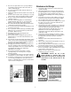
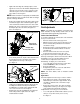
5. 6. 7. 8. 9. 10. 11. 12. 13. 14. 15. 16. 17. 18. 19. 20. Maintenance And Storage Never run an engine indoors or in a poorly ventilated area. Engine exhaust contains carbon monoxide, an odorless and deadly gas. Do not operate machine while under the influence of alcohol or drugs. Muffler and engine become hot and can cause a burn. Do not touch. Exercise extreme caution when operating on or crossing gravel surfaces. Stay alert for hidden hazards or traffic.
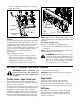
SECTION 2: ASSEMBLING YOUR SNOW THROWER NOTE: Any reference in this manual to the left or right side of the snow thrower is observed from the operator’s position. Upper Handle Unpacking Steering Cable • • • • • Remove staples from the top, sides, and ends of the shipping crate. Set panels aside to avoid tire punctures or personal injury. Remove and discard plastic bag that covers unit. Roll the unit out of the crate. Check the crate thoroughly for loose parts before discarding.
• Tighten the two wing nuts already in place on the upper holes and secure the handles firmly.Slide the shift rod connector down over the end of the lower shift rod. Tap the connector until it locks over the lower shift rod. See Figure 2. Alternator Lead Alternator Lead NOTE: If the connector is not properly assembled, the shift rod will pivot and you will not be able to change speeds or change directions.
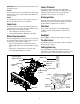
• Recheck adjustment; readjust as necessary and tighten the jam nut. Shave Plate “Z” End Carriage Bolts Jam Nut High Skid Shoes Auger Control Cable Low Hex Nuts Figure 8 Figure 7 NOTE: Make certain the entire bottom surface of skid shoe is against the ground to avoid uneven wear on the skid shoes. Skid Shoes The space between the shave plate and the ground can be adjusted by repositioning the skid shoes.
Chute Tilt Control IMPORTANT: Always release traction the control before changing speeds. The distance snow is thrown can be changed by adjusting the angle of the chute assembly. Move the chute tilt control forward to decrease the distance, toward the rear to increase. See Figure 9. Forward Your snow thrower has six forward (F) speeds. Position number one (1) is the slowest and position number six (6) is the fastest. Reverse Discharge Chute Your snow thrower has two reverse (R) speeds.
SECTION 4: OPERATING YOUR SNOW THROWER Before Starting WARNING: The electric starter is equipped with a grounded three-wire power cord and plug and is designed to operate on 120 volt AC household current. It must be used with a properly grounded three-prong receptacle at all times to avoid the possibility of electric shock. Follow all instructions carefully prior to operating the electric starter.
To Stop Engine • • • Run engine for a few minutes before stopping to help dry off any moisture on the engine. To help prevent possible freeze-up of starter, proceed as follows. IMPORTANT: NEVER move the shift lever without first releasing the traction control. Doing so will cause premature wear to the drive system’s friction wheel. Electric Starter: • Connect power cord to switch box on engine, then to 120 volt AC receptacle.
• • • Loosen the jam nut on the traction drive cable and thread the cable in or out as necessary. Refer to Figure 7. Retighten the jam nut to secure the cable when correct adjustment is reached. Reassemble the frame cover. Shift Lever Hairpin Clip NOTE: If you placed plastic film under the gas cap, be certain to remove it before operating the snow thrower.
• • • • Discharge Chute warranty, operator must maintain the snow thrower as instructed in this manual. Some adjustments will have to be made periodically to maintain your unit properly. All adjustments in the service and adjustments sections of this manual should be checked at least once each season. Follow the maintenance schedule given below. Periodically check all fasteners and hardware to make sure these are tight.
• • Carefully spin the auger around by hand to disperse the lubricant. Reinstall the shear bolts. • Traction Control / Auger Control Lock Check Friction Wheel Rubber The cams on the ends of the control rods which interlock the traction drive and auger drive clutches must be lubricated at least once a season or every 25 hours of operation using a multi-purpose automotive grease. The cams can be accessed beneath the handle panel. See Figure 14.
• • • • • Remove the six carriage bolts (three per side), belleville washers and hex nuts which attach slide shoes to the snow thrower on two sides. See Figure 8. Reassemble new slide shoes with the hardware removed earlier (cupped side of belleville washer against the slide shoes). Make certain the slide shoes are adjusted to be level. To remove the shave plate, remove slide shoe as well as the carriage bolts, belleville washers and hex nuts which attach shave plate to the snow thrower housing.
Auger Belt Idler Pulley Auger Pulley Brake Bracket Assembly • assembly and secure with flat washer and cotter pin. Reassemble the large shoulder bolt and lock washer. Refer to Figure 17. Reassemble belt cover and chute crank. Changing Friction Wheel Rubber The rubber on the friction wheel is subject to wear and should be checked after the first 25 hours of operation, and periodically thereafter. Replace the friction wheel rubber if any signs of wear or cracking are found.
• • • • • • the right side of the hex shaft will fall and the sprocket should remain hanging lose in the chain. Lift the friction wheel assembly out between the axle shaft and the drive shaft assemblies. Remove the six screws from both sides of the friction wheel assembly and remove friction wheel rubber from between the friction wheel plate. See Figure 20. Reassemble the new friction wheel rubber to the friction wheel assembly, tightening the six screws in rotation and with equal force.
SECTION 8: TROUBLESHOOTING Problem Cause Remedy Engine fails to start. 1. 2. 3. 4. 5. 6. 7. Fuel tank empty, or stale fuel. Blocked fuel line. Choke not in ON position Faulty spark plug. Safety key not in ignition switch on engine. Spark plug wire disconnected. Primer button not being used properly. 1. 2. 3. 4. 5. 6. 7. Fill tank with fresh gasoline. Clean the fuel line. Move switch to ON position Clean, adjust gap or replace. Insert the key fully into the switch. Connect spark plug wire.
Model 31AE993J401 47 8 8 43 25 13 16 14 40 21 31 42 25 8 7 21 5 14 1 25 55 51 48 29 27 13 17 45 25 18 14 58 3 26 34 54 56 25 53 9 50 57 14 34 26 32 13 44 22 5 13 33 52 46 49 41 25 14 5 11 2 35 19 13 28 6 12 15 36 37 38 29 20 24 13 29 30 10 4 23 39 25 18 NOTE: For painted parts, please refer to the list of color codes below. Please add the applicable color code, wherever needed, to the part number to order a replacement part.
Model 31AE993J401 Ref. No. 1. 2. 3. 4. 5. 6. 7. 8. 9. 10. 11. 12. 13. 14. 15. 16. 17. 18. 19. 20. 21. 22. 23. 24. 25. 26. 27. 28. 29. Part No. 05244A 618-0281A 684-0090A 710-0371 710-0451 710-0459A 710-0528 710-0604A 710-0891 711-0640 711-0677 712-0116 712-0429 712-3010 714-0104 714-0126 714-0135 715-0118 731-1696 732-0858 736-0119 736-0159 736-0169 736-0174 736-0242 736-0250 736-0271 736-3008 737-0318 Ref. No.
Model 31AE993J401 18 12 63 8 17 76 79 9 18 50 26 62 80 11 16 66 49 41 15 48 61 4 19 56 36 45 45 35 30 65 3 42 34 67 27 75 23 33 47 55 33 22 56 38 6 14 55 22 71 64 57 20 13 46 2 21 46 40 46 29 13 43 46 60 50 61 48 27 31 43 47 80 15 19 55 68 7 62 55 51 58 56 70 66 26 51 20 29 10 45 39 60 44 28 24 35 32 1 16 18 55 42 5 54 31 47 73 45 55 53 69 30 31 59 37 31 77 52 18 18 NOTE: For painted parts, please refer to the list of colo
Model 31AE993J401 Ref. No. 1. 2. 3. 4. 5. 6. 7. 8. 9. 10. 11. 12. 13. 14. 15. 16. 17. 18. 19. 20. 21. 22. 23. 24. 25. 26. 27. 28. 29. 30. 31. 32. 33. 34. 35. 36. 37. 38. 39. 40. Part No.
Model 31AE993J401 36 37 39 35 33 A 32 A 9 22 11 6 42 11 40 29 34 44 38 1 7 21 13 15 23 10 43 41 22 28 24 3 A 27 9 13 21 32 31 5 A 15 35 18 33 1 19 6 17 16 21 26 4 19 7 23 25 30 19 5 15 19 34 4 8 2 14 12 20 NOTE: For painted parts, please refer to the list of color codes below. Please add the applicable color code, wherever needed, to the part number to order a replacement part.
Model 31AE993J401 Ref. No. 1. 2. 3. 4. 5. 6. 7. 8. 9. 10. 11. 12. 13. 14. 15. 16. 17. 18. 19. 20. 21. 22. 23. 24. 25. 26. 27. Part No. 646-0012 684-0053B 705-5266 710-0216 710-0347 710-0458 710-0572 710-0891 710-3015 711-0677 712-0287 712-0429 712-3010 714-0101 714-0104 720-0201A 720-0284 726-0100 736-0105 736-0185 736-0242 736-0270 736-0275 741-0475 747-0624 747-0983 747-0997 Ref. No. Part Description Cable Assembly: Auger/Drive Chute Crank Assembly Chute Crank Bracket Hex Screw 3/8-16 x .
Model 31AE993J401 23 6 24 10 15 26 25 15 6 14 22 18 16 12 8 14 7 9 4 21 1 3 11 13 13 5 17 2 19 3 20 Ref. No. 1. 2. 3. 4. 5. 6. 7. 8. 9. 10. 11. 12. 13. 14. 15. 16. 17. 18. 19. 20. 21. 22. 23. 24. 25. 26. 24 Part No.
Model 31AE993J401 26 34 33 Ref. No. 22 29 35 22 25 30 6 23 38 12 36 27 37 22 34 26 26 32 20 24 28 31 30 4 6 33 15 21 6 19 3 10 16 17 6 18 8 10 12 14 13 2 6 4 11 1 7 9 5 25 Part No. Description 1. 710-0276 Carriage Screw 2. 710-0458 Carriage Bolt 5/16-18 x 1.75” 3. 710-0805 Hex Bolt 5/16-18 x 1.5” 4. 710-0896 Hex AB Screw 1/4-14 x .625” 5. 710-3015 Hex Screw 1/4-20 x .75” 6. 712-0429 Hex Lock Nut 7. 712-3027 Hex Flange Lock Nut 8.
Notes 26
MANUFACTURER’S LIMITED WARRANTY FOR: c. Routine maintenance items such as lubricants, filters, blade sharpening and tune-ups, or adjustments such as brake adjustments, clutch adjustments or deck adjustments; and normal deterioration of the exterior finish due to use or exposure. d. MTD does not extend any warranty for products sold or exported outside of the United States of America, its possessions and territories, except those sold through MTD’s authorized channels of export distribution.