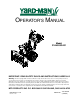
OPERATOR’S MANUAL Model 31AH553G401 IMPORTANT: READ SAFETY RULES AND INSTRUCTIONS CAREFULLY Warning: This unit is equipped with an internal combustion engine and should not be used on or near any unimproved forestcovered, brush-covered or grass-covered land unless the engine’s exhaust system is equipped with a spark arrester meeting applicable local or state laws (if any). If a spark arrester is used, it should be maintained in effective working order by the operator.
TABLE OF CONTENTS Content Page Important Safe Operation Practices................................................................... 3 Assembling Your Snow Thrower ....................................................................... 5 Know Your Snow Thrower ................................................................................. 8 Operating Your Snow Thrower .......................................................................... 10 Making Adjustments ........................................
SECTION 1: IMPORTANT SAFE OPERATION PRACTICES This symbol points out important safety instructions which, if not followed, could endanger the personal safety and/or property of yourself and others. Read and follow all instructions in this manual before attempting to operate this machine. Failure to comply with these instructions may result in personal injury. When you see this symbol—heed its warning.
5. 6. 7. 8. 9. 10. 11. 12. 13. 14. 15. 16. 17. 18. 19. 20. Maintenance And Storage Never run an engine indoors or in a poorly ventilated area. Engine exhaust contains carbon monoxide, an odorless and deadly gas. Do not operate machine while under the influence of alcohol or drugs. Muffler and engine become hot and can cause a burn. Do not touch. Exercise extreme caution when operating on or crossing gravel surfaces. Stay alert for hidden hazards or traffic.
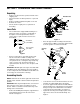
SECTION 2: ASSEMBLING YOUR SNOW THROWER Unpacking • • • • • Remove screws from the top sides and ends of the shipping crate. Set panel aside to avoid tire punctures or personal injury. Remove and discard plastic bag that covers unit. Roll unit out of crate. Check crate thoroughly for loose parts before discarding. Handle Panel Loose Parts • Upper Handle The snow thrower is shipped with following loose parts in the carton. See Figure 1 for illustration, description of item and part number.
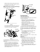
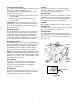
• Slide the shift rod connector down over the end of the lower shift rod. See Figure 4. Tap the connector until it locks on the lower shift rod. Lower Handle NOTE: If the connector is not properly assembled, the shift rod will pivot and you will not be able to change direction or speed of the snow thrower.
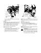
“Z” End Shave Plate Jam Nut Carriage Bolts Skid Shoes Auger Control Cable • Hex Nuts Figure 8 Recheck adjustment; readjust as necessary and tighten the jam nut. NOTE: Make certain the entire bottom surface of skid shoe is against the ground to avoid uneven wear on the skid shoes. Tire Pressure (Pneumatic Tires) The space between the shave plate and the ground can be adjusted by repositioning the skid shoes. For close snow removal, place skid shoes in the low position.
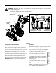
SECTION 3: KNOWING YOUR SNOW THROWER WARNING: Be familiar with all the controls and their proper operation. Know how to stop the machine and disengage them quickly. • See Figure 9 to identify all the controls described below.
Electric Chute-Rotation Switch Skid Shoe The electric chute-rotation switch is located on the left side of the snow thrower handle panel. To change the direction in which discharged snow is thrown, proceed as follows: The position of the skid shoe is determined by the condition of the ground from where snow has to be removed. Refer to page 7 for details. • The fuel shut-off valve is located under the fuel tank. This valve controls fuel flow from the tank.
SECTION 4: OPERATING YOUR SNOW THROWER Before Starting • • WARNING: Read, understand, and follow all instructions and warnings on the machine and in this manual before operating. • • • • The spark plug wire was disconnected for safety. Attach spark plug wire to spark plug before starting. Make certain the auger and drive clutch levers are in the disengaged (released) position. Check oil and gasoline level and add if necessary.
• • • Recoil Starter: With engine running, pull starter rope with a rapid, continuous full arm stroke three or four times. Pulling the starter rope will produce a loud clattering sound, which is not harmful to the engine or starter. Wipe all snow and moisture from the carburetor cover in the area of the control levers. Also, move control levers back and forth several times. Leave throttle control lever in the STOP or OFF position. Rotate the choke control in the FULL choke position.
SECTION 5: MAKING ADJUSTMENTS WARNING: NEVER attempt to clean • chute or make any adjustments while engine is running. Traction Control Remove the hairpin clip and slide the connector up to separate the upper shift rod from the lower shift rod. See Figure 12. Shift Lever Hairpin Clip Refer to Final Adjustments on page 6 to adjust traction control.
SECTION 6: MAINTAINING YOUR SNOW THROWER Drive and Shifting Mechanism Before lubricating, repairing, or inspecting, disengage all clutch levers and stop engine. Wait until all moving parts have come to a complete stop. Disconnect spark plug wire and ground it against the engine to prevent unintended starting. At least once a season or after every 25 hours of operation, remove rear cover. Lubricate any chains, sprockets, gears, bearings, shafts, and shifting mechanism at least once a season. See Figure 14.
SECTION 7: SERVICING YOUR SNOW THROWER WARNING: Before servicing, repairing, or • inspecting, disengage all clutch levers and stop engine. Wait until all moving parts have come to a complete stop. Disconnect spark plug wire and ground it against the engine to prevent unintended starting. To remove shave plate, remove the carriage bolts, belleville washers and hex nuts which attach it to the snow thrower housing.
• • Unhook the idler spring from the hex bolt on the auger housing. See Figure 19. Back out the stop bolt until the support bracket rests on the auger pulley. See Figure 20. Friction Wheel NOTE: It may be necessary to loosen the six nuts that connect the frame to the auger housing to aid in belt removal. • Drive Plate Drive Belt Lift the rear auger belt from the auger pulley, and slip belt between the support bracket and the auger pulley. See Figure 19. Repeat this step for the front auger belt.
• • • Holding the friction wheel assembly, slide the hex shaft out of the left side of the frame. See Figure 21. The spacer on the right side of the hex shaft will fall and the sprocket should remain hanging loose in the chain. Lift the friction wheel assembly out between the axle shaft and the drive shaft assemblies. Remove the six screws from the friction wheel assembly (three from each side). Remove the friction wheel rubber from between the friction wheel plates. See Figure 22.
SECTION 9: TROUBLESHOOTING Problem Cause Remedy Engine fails to start. 1. 2. 3. 4. 5. 6. 7. 8. Fuel tank empty, or stale fuel. Blocked fuel line. Choke not in ON position Faulty spark plug. Safety key not in ignition switch on engine. Spark plug wire disconnected. Primer button not being used properly. Fuel shut-off valve closed. 1. 2. 3. 4. 5. 6. 7. 8. Fill tank with fresh gasoline. Clean the fuel line. Move switch to ON position Clean, adjust gap or replace. Insert the key fully into the switch.
SECTION 10: PARTS LIST FOR MODEL 31AH553G401 68 57 58 27 57 58 55 65 72 70 53 73 72 27 69 82 71 27 68 80 74 63 59 67 69 27 56 64 58 66 62 77 60 66 58 54 81 76 78 31 45 83 79 11 75 61 45 15 9 5 29 51 40 5 46 37 47 5 2 8 14 13 17 24 5 20 22 10 14 21 3 50 9 11 40 18 16 41 12 4 26 25 31 1 43 9 11 42 27 19 15 52 35 39 14 35 36 48 10 49 38 For reference only 23 7 44 For reference only 44 32 28 30 18 NOTE: For painted parts, please refer to t
MODEL 31AH553G401 Ref. No. 1. 2. 3. 4. 5. 7. 8. 10. 11. 12. 13. 14. 15. 16. 17. 18. 19. 20. 21. 22. 23. 24. 25. 26. 27. 28. 29. 30. 31. 32. 35. 36. 37. 38. 39. 40. 41. 42. 43. 44. Part No.
MODEL 31AH553G401 1 2 3 4 5 6 18 11 10 15 14 9 7 8 12 13 16 22 23 27 28 34 21 10 25 23 13 20 26 35 30 38 22 18 32 31 33 16 37 36 41 39 40 17 NOTE: For painted parts, please refer to the list of color codes below. Please add the applicable color code, wherever needed, to the part number to order a replacement part. For instance, if a part numbered 700-xxxx is painted Yard-Man Green, the part number to order would be 700-xxxx-0665.
MODEL 31AH553G401 Ref. No. 1. 2. 3. 4. 5. 6. 7. 8. 9. 10. 11. 12. 13. 14. 15. 16. 17. 18. 20. 21. 22. Part No. 712-0116 756-0178 784-5632A 710-0459A 738-0281 736-0167 732-0611 712-3068 710-0276 736-0119 05931A 741-0309 710-0451 705-5226 684-0041C 712-3010 712-0429 736-0242 737-0318 731-1379B 712-0324 Part Description Ref. No. 23. 24. 25. 26. 27. 28. 29. 30. 31. 32. 33. 34. 35. 36. 37. 38. 39. 40. 41. 42. Lock Jam Nut 3/8-24 Flat Idler Auger Idler Arm Hex Cap Screw 3/8-24 x 1.
MODEL 31AH553G401 28 29 30 1 27 1 2 26 IMPORTANT: For a proper working machine, use Factory Approved Parts. V-BELTS are specially designed to engage and disengage safely. A substitute (non OEM) V-Belt can be dangerous by not disengaging completely 3 4 9 8 4 7 11 10 16 19 12 15 6 5 16 19 16 21 16 22 13 23 14 18 17 20 24 NOTE: For painted parts, please refer to the list of color codes below.
MODEL 31AH553G401 Ref. No. 1. 2. 3. 4. 5. 6. 7. 8. 9. 10. 11. 12. 13. 14. 15. Part No. 710-1652 731-1324 732-0710 710-0627 710-3005 05896A 748-0234 756-0987 754-0346 756-0986 736-0270 710-0230 756-0313 710-1245 712-0181 Part Description Hex Washer Screw 1/4-20 x .625 Belt Cover Extension Spring Hex Screw 5/16-24 x .75 Hex Cap Screw 3/8-16 x 1.25 Drive Clutch Idler Bracket Shoulder Spacer Pulley Half V-Belt Pulley Half Bell Washer Hex Cap Screw 1/4-28 x .
MODEL 31AH553G401 40 56 54 39 8 35 45 55 52 50 8 45 41 NOTE: Actual position of the steering controls on the handle shown here 57 35 54 47 13 50 28 21 8 8 34 16 30 36 25 34 18 44 34 22 4 31 50 41 14 21 37 13 32 38 3 25 53 21 10 50 20 57 34 36 17 38 32 42 31 13 21 19 33 6 23 49 29 8 31 43 37 12 8 46 20 5 31 2 55 13 34 34 34 24 8 1 9 51 12 7 26 27 15 28 30 48 10 45 35 10 24 16 8 10 NOTE: For painted parts, please refer to the list of color
MODEL 31AH553G401 Ref. No. 1. 2. 3. 4. 5. 6. 7. 8. 9. 10. 11. 12. 13. 14. 15. 16. 17. 18. 19. 20. 21. 22. 23. 24. 25. 26. 27. 28. 29. Part No. 618-0043 618-0044 618-0303B 656-0012A 684-0014B 684-0042C 684-0131A 710-0599 710--0809 710-1652 711-1267 711-1268 711-1364 712-0703 712-0711 712-3017 713-0233 713-0374 713-0413 713-0472 714-0104 714-0474 716-0102 721-0263 732-0209 732-0264 736-0105 736-0142 736-0160 Part Description Ref. No.
MODEL 31AH553G401 26
Your Notes Comments Date 27
MANUFACTURER’S LIMITED WARRANTY FOR: The limited warranty set forth below is given by MTD PRODUCTS INC (“MTD”) with respect to new merchandise purchased and used in the United States, its possessions and territories. MTD warrants this product against defects in material and workmanship for a period of two (2) years commencing on the date of original purchase and will, at its option, repair or replace, free of charge, any part found to be defective in material or workmanship.