Operator's Manual Two-Stage Snow Thrower Model 5KL IMPORTANT: Read safety rules and instructions carefully before operating equipment.
TABLEOFCONTENTS Content Customer Support Important SafeOperation Practices SettingUpYourSnowThrower Operating YourSnowThrower Maintaining YourSnowThrower Page 2 3 5 8 12 Content Service & Adjustments Off-Season Storage Troubleshooting Illustrated Parts List Page 14 18 19 20 Warranty Back Cover FINDINGMODELNUMBER This Operator's Manual is an important part of your new snow thrower. It will help you assemble, prepare and maintain the unit for best performance. Please read and understand what it says.
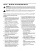
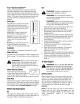
SECTION1: IMPORTANT SAFEOPERATIONS PRACTICES _ This and/or symbol property points out important and safety instructions which, notinstructions followed, could theARNING" personal safety of yourself others. Read and followif all in thisendanger manual before attempting to operate this machine. Failure to comply with these instructions may result in personal injury. When you see this symbol--heed its warning.
Operation 1. 2. 3. 4. 5. 6. 7. 8. Do not put hands or feet near rotating parts, in the auger/impeller housing or chute assembly. Contact with rotating parts can amputate hands and feet. The auger/impeller control is a safety device. Never bypass its operation. Doing so makes the machine unsafe and may cause personal injury. The controls must operate easily in both directions and automatically return to the disengaged position when released. Never operate with a missing or damaged chute assembly.
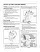
SECTION1: SETTINGUPYOURSNOWTHROWER IMPORTANT:This unit is shipped with the engine full of oil. After assembly, see page 9 for fuel and oil details. NOTE: If the connector is not properly assembled, the shift rod will pivot and changing speed or direction of the snow thrower will not be possible. RemovingFromCarton 1. 2. 3. Cut the corners of the carton and lay the sides flat on the ground. Remove all packing inserts. Move the snow thrower out of the carton.
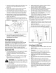
7. Insert the round end of the chute control box on the short tube of the chute assembly as shown in Figure 3C. Insert other end of the chute control box into the chute support tube as shown in Figure 3C. Insert the clevis pin, earlier removed, through the holes on the chute control box and chute support rod. Secure with the hairpin clip. See Figure 3D. 4. 10. Slip the cables, running from the handle panel to the chute, into the cable guide located on top of the engine. See Figure 4. 11.
8. Ifthewheelscanstillbeturnedwhenyouengage thedrivecontrol,loosenthejamnutonthedrive cableandthreadthecableinoneturn.Recheck the adjustment andrepeatifneeded. 9. Tightenthejamnuttosecurethecablewhen correctadjustment is reached. NOTE: For further details, refer to the Adjustment 2. 3. desired position. See Figure 7. Make certain the entire bottom surface of skid shoes are against the ground to avoid uneven wear on the skid shoes. Tighten nuts and bolts securely. o o section on page 17.
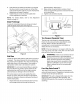
SECTION2: OPERATING YOURSNOWTHROWER KnowTheControls Read this owner's manual and safety rules before operating your snow thrower. Compare Figure 8 with your snow thrower to familiarize yourself with the location of various controls and adjustments. Maintain safety while learning about the controls and operating the unit. Save this manual for future reference. Drive Control Shift Lever Four-Way Chute ControF M Auger Control Headlight Wheel Steering Control Fuel Tank Chute Assembly \\\\\\\\\\ Clean-Out Tool
Gas Four-Way ChuteControlTM This four-way control lever is meant to control the direction and distance of snow discharge from the chute. Press the button on the knob and turn it left or right to rotate the chute to the direction that snow will be thrown. Tilt the lever forward to decrease the distance snow will be thrown, and backwards to increase distance. WARNING: Gasoline is flammable; use caution when handling or storing it.
ColdStart _ properly ARNING" grounded The at electric all times starter to avoid mustthe be possibility of electric shock which may be injurious to the operator. 1. Determine whether your house wiring is a threewire grounded system. Ask a licensed electrician if you are not certain. 1. 2. 3. 4. 5. Move throttle control to FAST position. Turn fuel valve on, if so equipped. Push key into the ignition slot and snap in place. Do not turn key, Rotate choke control to FULL choke position.
NOTE:The unusual sound from pulling the starter rope in case of the recoil starter, or from spinning the starter in case of the electric starter, will not harm the engine. 6. 7. ToStopTheSnowThrower 1. 2. 3. 8. To stop the wheels, release the drive control on the snow thrower. To stop throwingsnow, release auger control. To stop engine, push throttle control lever to "stop" or "off" and remove ignition key (Do not turn key) to prevent unauthorized use of equipment. 9.
DriftCutters (on models If your unit is not equipped with drift cutters, contact Customer Support as instructed on page 2 for information regarding price and availability. Snow Thrower ModelDrift Cutter Kit: so equipped) Drift cutters should be used when operating the snow thrower in heavy drift conditions. On models so equipped, drift cutters are assembled to the auger housing inverted.
Drive/Auger Control Lock: The cam on the ends of the control rods which interlock the drive and auger controls must be lubricated at least once a season or every 25 hours of operation using a multi-purpose automotive grease. The cam can be accessed beneath the handle panel. 5. Re-attach frame cover to the snow thrower and put the equipment back to operating position. CheckChuteCables Once a season or every 25 hours of operation, whichever is earlier, check whether the chute cables have slackened.
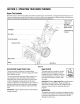
SECTION4: SERVICE& ADJUSTMENT _ ARNING" stopit engine, disconnect spark plug wire Always and move away from spark plug before performing adjustments or repairs. Always wear safety glasses during operation or while performing any adjustments or repairs. ServicingAugers The augers are secured to the spiral shaft with two shear pins and cotter pins. See Figure 12. 1. 2. Carriage Bolt Skid Shoe If the augers do not turn, check to see if the pins have sheared.
A Belt Self-Tapping _rew Screw /i / i Shoulder Screw B Spring Mounting Drive Belt Figure 16 4. 5. -Auger Belt 6. 7. 8. 9. Figure 14 AugerBelt 1. Wrap auger belt around the auger pulley. See Figure 16. Re-insert shoulder screw into the mounting bracket and tighten to secure. Wrap auger belt behind the idler. Reattach the spring to the bolt where it was earlier secured. Re-install frame cover and flip the snow thrower back to the operating position. Wrap auger belt around the engine pulley.
, Back out the stop bolt to create sufficient gap between the friction wheel disc and the drive pulley. Pull the drive belt from around the drive pulley and clear it off the friction wheel disc. See Figure 18. Drive Cover / Friction Wheel Drive Pulley Figure 19 , Figure 18 5. 6. 7. 8. Now moving to the other side of the snow thrower again, slide the belt off the crankshaft.
2. 10. Insert the shift arm assembly into the friction wheel assembly and hold assembly in position. See Figure 22. 11. Slide hex gear shaft through right side of the housing and the friction wheel assembly. 12. Insert the hex gear shaft through the sprocket and the spacer. Make certain that chain engages both the large and the small sprocket. 3. 4. NOTE: If the sprocket fell from the snow thrower while removing the hex gear shaft, place the sprocket on the hex gear shaft.
7. Check for correct adjustment before operating the snow thrower. Chute Control SkidShoe Refer to page 7 for details. ChuteControl Once a season or every 25 hours of operation, whichever is earlier, check whether the chute control cables have slackened. If the chute does not rotate fully or its pitch cannot be moved up or down, the chute control cables will have to be adjusted. To adjust these cables, proceed as follows: 1. To tighten cable, loosen the top nut and tighten the bottom nut on the cable.
SECTION6: TROUBLESHOOTING Problem Cause Remedy Engine fails to start. 1. 2. 3. 4. 5. 6. 7. 8. Fuel tank empty, or stale fuel. Blocked fuel line. Choke not in ON position. Faulty spark plug. Safety key not in ignition switch on engine. Spark plug wire disconnected. Primer button not being used properly. Fuel shut-off valve closed. (If Equipped) 1. 2. 3. 4. 5. 6. 7. 8. Fill tank with fresh gasoline. Clean the fuel line. Move switch to ON position. Clean, adjust gap or replace.
SECTION7: PARTSLISTFORMODEL5KL 10 12 14 33 ._8 16 17 29 32 27 24 25 .....68 4O // /// / "\ 42 59 62 2O
Model5KL Ref. No. Part No. Description Ref. No. Part No. Description 1. 731-04427A Upper Chute 36. 784-5580 Slide Shoe 2. 712-04063 3. 784-5594 Flange Lock Nut, 5/16-18 Cable Bracket 37. 39. 710-0451 790-00121 Carriage Bolt Shave Plate 4. 731-1313C Chute Tilt Cable Guide 40. 684-04057 5. 710-0262 6. 710-0895 Carriage Bolt, 5/16-18 x 1.50 Hi-Lo Screw, 1/4-15 x 0.75 41. 42. 717-04126 721-0327 Impeller Assembly Worm Shaft 7. 710-04071 Carriage Bolt, 5/16-18 x 1.0 43.
Model5KL 11 12 17 55 15 18 _t 20 / / B / 26 23 / / / / / / 37 54 32 '33 22 46 47 53 50 i i;i!¸ .
Model5KL Ref. No. Part No. 1. 684-04106 2. 746-0778 3. Ref. No. Description Part No. Description Handle Engagement Assembly RH 30. 750-0963 Shift Rod Connector Cable Z- Fitting Lock Plate 31. 714-0104 Hairpin Clip 731-04894 32. 753-04864 Joystick Housing w/Fasteners 4. 711-04287 Pivot Rod 33. 753-04863 Knob Assembly w/Trigger 5. 735-0199A Rubber Bumper 34. 790-00131 Joystick Bracket 6. 710-04354 35. 710-04187 Hi-Lo Screw, 1/4-15 x 0.5 7. 731-04896 Screw, 1/4-20 x.
Model5KL 2 60 73 59 55 56 63 64 53 65 66 5O 51 52 48 72 71 9 11 2O 18 19 26 27 35 33 41A 42_ 41B _ 42H "_(_ ""°@_ 42B_ c S ___442b 42G 24
Model5KL RefNo. Part No. PaA No. Description B. 713-04010 Sprocket C. 714-0214 Key Cable Guide D. 750-1177 Spacer 711-1268A Actuator Shaft E. 618-0577A 5. 746-04086 Drive Clutch Cable F. 717-1209A 6. 7. 732-0209 790-00055 Extension Spring Roller Bracket G. H. 736-0502 736-0336 Planetary Carr. Assembly Gear, 12T Flat Washer 8. 684-04140 Shift Rod Assembly I. 717-1210A Gear, 18T 9. 750-04312 717-1495B Planetary Ring Gear 10. 711-1364 Axle Support Tube Clevis Pin J. K.
Safety& DecorativeLabels OPERATORS VIEW 777122363 777D08367 777122347 777S32066 777D08384 (MODEL 26 PLATE)
NOTES 27
MANUFACTURER'S LIMITED WARRANTY FOR: YaRD.MaN TM ® The limited warranty set forth below is given by MTD LLC with respect to new merchandise purchased and used in the United States, its possessions and territories. "MTD" warrants this product against defects in material and workmanship for a period of two (2) years commencing on the date of original purchase and will, at its option, repair or replace, free of charge, any part found to be defective in materials or workmanship.