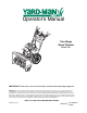
Operator’s Manual Two-Stage Snow Thrower Model 5KL IMPORTANT: Read safety rules and instructions carefully before operating equipment. Warning: This unit is equipped with an internal combustion engine and should not be used on or near any unimproved forestcovered, brush-covered or grass-covered land unless the engine’s exhaust system is equipped with a spark arrester meeting applicable local or state laws (if any).
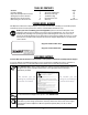
TABLE OF CONTENTS Content Customer Support Important Safe Operation Practices Setting Up Your Snow Thrower Operating Your Snow Thrower Maintaining Your Snow Thrower Content Service & Adjustments Off-Season Storage Troubleshooting Illustrated Parts List Warranty Page 2 3 5 8 12 Page 14 18 19 20 Back Cover FINDING MODEL NUMBER This Operator’s Manual is an important part of your new snow thrower. It will help you assemble, prepare and maintain the unit for best performance.
SECTION 1: IMPORTANT SAFE OPERATIONS PRACTICES WARNING: This symbol points out important safety instructions which, if not followed, could endanger the personal safety and/or property of yourself and others. Read and follow all instructions in this manual before attempting to operate this machine. Failure to comply with these instructions may result in personal injury. When you see this symbol—heed its warning.
Operation unclogging, shut off engine and remain behind handles until all moving parts have stopped completely. 19. Use only attachments and accessories approved by the manufacturer (e.g. wheel weights, tire chains, cabs etc.). 20. If situations occur which are not covered in this manual, use care and good judgment. Contact your dealer or telephone 1-800-800-7310 for assistance and the name of your nearest servicing dealer. 1.
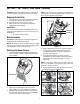
SECTION 1: SETTING UP YOUR SNOW THROWER NOTE: If the connector is not properly assembled, the shift rod will pivot and changing speed or direction of the snow thrower will not be possible. IMPORTANT: This unit is shipped with the engine full of oil. After assembly, see page 9 for fuel and oil details. Removing From Carton 1. Cut the corners of the carton and lay the sides flat on the ground. Remove all packing inserts. 2. Move the snow thrower out of the carton. 3.
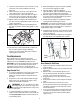
4. While standing in the operator’s position (behind the snow thrower) engage the auger. 5. Allow the auger to remain engaged for approximately ten (10) seconds before releasing the auger control. Repeat this several times. 6. With the engine running in the FAST position and the auger control in the disengaged “up” position, walk to the front of the machine. 7. Confirm that the auger has completely stopped rotating and shows NO signs of motion. 7.
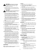
8. If the wheels can still be turned when you engage the drive control, loosen the jam nut on the drive cable and thread the cable in one turn. Recheck the adjustment and repeat if needed. 9. Tighten the jam nut to secure the cable when correct adjustment is reached. High Position Middle Position Low Position NOTE: For further details, refer to the Adjustment section on page 17. Skid Shoe Skid Shoe Locate the shave plate and the skid shoes in Figure 7 on page 8.
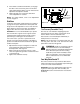
SECTION 2: OPERATING YOUR SNOW THROWER Know The Controls Read this owner’s manual and safety rules before operating your snow thrower. Compare Figure 7 with your snow thrower to familiarize yourself with the location of various controls and adjustments. Maintain safety while learning about the controls and operating the unit. Save this manual for future reference.
Four- Way Chute Control™ Gas This four-way control lever is meant to control the direction and distance of snow discharge from the chute. Press the button on the knob and turn it left or right to rotate the chute to the direction that snow will be thrown. Tilt the lever forward to decrease the distance snow will be thrown, and backwards to increase distance. WARNING: Gasoline is flammable; use caution when handling or storing it.
Cold Start WARNING: The electric starter must be 1. Move throttle control to FAST position. 2. Turn fuel valve on, if so equipped. 3. Push key into the ignition slot and snap in place. Do not turn key. 4. Rotate choke control to FULL choke position. 5. Push the primer button while covering the vent hole. Remove your finger from the primer between primes. Do not prime if temperature is above 50o F; prime two times between 50o F and 15o F; and prime four times below 15o F. 6.
6. When clearing the first pass through the snow, control speed of snow thrower according to the depth and condition of snow. 7. To turn the unit left or right, squeeze the respective wheel steering control. See Figure 7. 8. On each succeeding pass, readjust the chute to the desired position and slightly overlap previous path. 9. After the area is cleared, stop the snow thrower following instructions given below.
Drift Cutters (on models so equipped) If your unit is not equipped with drift cutters, contact Customer Support as instructed on page 2 for information regarding price and availability. Drift cutters should be used when operating the snow thrower in heavy drift conditions. Snow Thrower ModelDrift Cutter Kit: On models so equipped, drift cutters are assembled to the auger housing inverted.
• 5. Re-attach frame cover to the snow thrower and put the equipment back to operating position. Drive/Auger Control Lock: The cam on the ends of the control rods which interlock the drive and auger controls must be lubricated at least once a season or every 25 hours of operation using a multi-purpose automotive grease. The cam can be accessed beneath the handle panel. Check Chute Cables Once a season or every 25 hours of operation, whichever is earlier, check whether the chute cables have slackened.
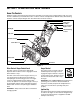
SECTION 4: SERVICE & ADJUSTMENT WARNING: Always stop engine, disconnect spark plug wire and move it away from spark plug before performing adjustments or repairs. Always wear safety glasses during operation or while performing any adjustments or repairs. Servicing Augers The augers are secured to the spiral shaft with two shear pins and cotter pins. See Figure 11 . Carriage Bolt Skid Shoe 1. If the augers do not turn, check to see if the pins have sheared. 2. Replace the pins if needed.
A Belt Cover Self-Tapping Screw Self-Tapping Screw Auger Pulley Shoulder Screw B Spring Mounting Bracket Engine Pulley Drive Belt Figure 15 4. Wrap auger belt around the auger pulley. See Figure 15. 5. Re-insert shoulder screw into the mounting bracket and tighten to secure. 6. Wrap auger belt behind the idler. Reattach the spring to the bolt where it was earlier secured. 7. Re-install frame cover and flip the snow thrower back to the operating position. 8. Wrap auger belt around the engine pulley.
4. Back out the stop bolt to create sufficient gap between the friction wheel disc and the drive pulley. Pull the drive belt from around the drive pulley and clear it off the friction wheel disc. See Figure 17. Drive Belt Drive Cover Bolt Friction Wheel Drive Pulley Spacer Stop Bolt Figure 18 6. Holding the friction wheel assembly, slide the hex gear shaft to the right. See Figure 19. The spacer on right side of hex gear shaft may fall. Figure 17 5.
2. With the drive control released, there must be 1/8” clearance between the friction wheel and the drive plate in all positions of the shift lever. 3. With the drive control engaged, the friction wheel must contact the drive plate (Figure 18). 4. If adjustment is necessary, loosen the jam nut on the drive cable and thread the cable in or out as necessary. Tighten the jam nut to secure the cable when correct adjustment is reached. Reassemble the frame cover. 10.
7. Check for correct adjustment before operating the snow thrower. Chute Control Skid Shoe Refer to page 7 for details. Chute Control Once a season or every 25 hours of operation, whichever is earlier, check whether the chute control cables have slackened. If the chute does not rotate fully or its pitch cannot be moved up or down, the chute control cables will have to be adjusted. To adjust these cables, proceed as follows: 1. To tighten cable, loosen the top nut and tighten the bottom nut on the cable.
SECTION 6: TROUBLESHOOTING Problem Cause Engine fails to start. 1. 2. 3. 4. 5. 6. 7. 8. Engine runs erratic. Remedy Fuel tank empty, or stale fuel. Blocked fuel line. Choke not in ON position. Faulty spark plug. Safety key not in ignition switch on engine. Spark plug wire disconnected. Primer button not being used properly. Fuel shut-off valve closed. (If Equipped) 1. Unit running on CHOKE. 2. Blocked fuel line or stale fuel. 3. Water or dirt in fuel system. 4. Carburetor out of adjustment. 1. 2. 3.
SECTION 7: PARTS LIST FOR MODEL 5KL 1 10 2 3 4 12 5 6 9 14 7 8 55 31 13 2 47 33 34 16 15 17 29 28 30 32 19 33 20 52 18 2 27 26 23 24 25 22 15 27 40 37 15 37 37 51 27 39 36 2 2 41 53 60 58 54 57 58 59 48 49 50 45 46 61 44 42 43 56 35 62 65 66 63 67 64 68 20 21
Model 5KL Ref. No. 1. 2. 3. 4. 5. 6. 7. 8. 9. 10. 12. 13. 14. 15. 16. 17. 18. 19. 20. 21. 22. 23. 24. 25. 26. 27. 28. 29. 30. 31. 32. 33. 34. 35. Part No. 731-04427A 712-04063 784-5594 731-1313C 710-0262 710-0895 710-04071 731-04861 731-2643 684-04116 714-0104 711-0415 749-04155 712-04065 756-0981A 710-0347 790-00080 736-0174 738-0281 790-00087 738-0143 790-00075 726-04012 741-0309 732-0611 710-0726 710-0909A 731-04705 710-0703 731-2635 684-04071 712-04064 736-0463 618-04172 Description Ref. No.
Model 5KL 1 2 3 4 5 6 11 7 8 12 13 21 17 14 9 55 10 B 15 16 A 18 22 44 19 20 42 B 23 24 11 26 43 41 25 56 40 A 28 36 27 29 39 38 31 30 37 54 32 33 45 34 54 46 52 47 35 48 49 51 53 50 22 22
Model 5KL Ref. No. Part No. Description Ref. No. 1. 2. 3. 4. 5. 6. 7. 8. 9. 10. 11. 12. 13. 14. 15. 16. 17. 18. 19. 20. 21. 22. 23. 24. 25. 26. 27. 28.
Model 5KL 1 2 56 73 57 58 60 3 59 55 56 63 54 64 65 66 50 67 48 51 52 55 53 49 5 72 68 1 47 71 69 4 46 7 6 45 8 10 9 11 1 12 18 20 43 13 14 21 22 44 41 61 17 15 19 1 24 25 26 39 38 23 16 42 28 27 29 62 70 36 30 16 31 37 32 34 1 17 33 40 1 41 43 42 43A 42C 41A 42H 42A 41B 42I 42B 41C 42J 42K 42D 42E 42F 42G 24 43B 43D 43C 43E 43F 35
Model 5KL Ref No. 1. 2. 3. 4. 5. 6. 7. 8. 9. 10. 11. 12. 13. 14. 15. 16. 17. 18. — 19. 20. 21. 22. 23. 24. 25. 26. 27. 28. 29. 30. 31. 32. 33. 34. 35. 36. 37. 38. 39. 40. 41. A. B C. 42. A. Part No.
Safety & Decorative Labels OPERATORS VIEW 777I22334 CHUTE DIRECTIONAL CONTROL CHUTE TILT DOWN PUSH BUTTON CHUTE ROTATE LEFT 777I22363 PUSH BUTTON CHUTE ROTATE RIGHT CHUTE TILT UP STARTING INSTRUCTIONS: DRIVE AUGER LOCK 1.) INSERT IGNITION KEY AND SNAP IN PLACE. 2.) SET CHOKE AND THROTTLE TO FULL (ON) 777D08367 POSITION. PUSH PRIMER BUTTON 3x. 3.) ROPE START: PULL SLOWLY UNTIL HARDER TO PULL, THEN PULL RAPIDLY TO START. REPEAT PRIMING IF NEEDED. ELECTRIC START: DO NOT USE IN RAIN.
NOTES 27
MANUFACTURER’S LIMITED WARRANTY FOR: The limited warranty set forth below is given by MTD LLC with respect to new merchandise purchased and used in the United States, its possessions and territories. “MTD” warrants this product against defects in material and workmanship for a period of two (2) years commencing on the date of original purchase and will, at its option, repair or replace, free of charge, any part found to be defective in materials or workmanship.