. and f \ ., ...' YARD -~.;1AN co. P. C. BOX 36940 CLE'JELAt'JD, OHIO 1410 West Ganson Street PRINTED.IN U..S.A.
. 3. 7. 9. tI, i' , b.,fj;, .;, RULES FO.~~SAFE OPERATION .; ~~ Your SNOW THROWER is a precision piece of snow throwing equipment. Engineering skill and experience have been combined to provide the ultimate in safety and efficiency. As with any type of power equipment, carelessnessor error on the part of the operator can result in injury. EXERCISE EXTREME CAUTION AT ALL TIMES. 1.. READ THE OWNER'S MANUAL CAREFULLY. - ,.
"'~-"" -, ., ,-~ ..,. -., ~,. ~ ...:.~~,:, , tE';' IFOR l_SUGGESTIONS i;J;~:"';, i. ..'; ~:'; ':.;~, GJNERAL SNOW " t.'~" !~ ~.FREE OPERATION ~I~;.;".;,~i:~~.':'.,-., ,,~~~~~; ~,~~ ~ ;::' ~:~c:;::,~".: ,~-- ~-, ..~~,--' :;,.,...' ,:',:";'.';-;, ,-.: ;1t5::~::.~;~:,t..:~"-,,!:I~,~';~~t I..THRQWJNG I.fi;r.:.";;,~~..:, '::J..~o.i:.:..-""C,' IfAIW'Y' keep ~re~t~ , ,;j:~i, .' co.' ~ ;-"(.;.,., ... 'c~i!i!;:~:,J!: ~ 2.~~ Always start engine with machine on level. Sl!~~.'.
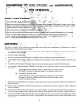
UNPACKING AND SET-UP 1. Be sure carton is right side UP. cut end panels out and fold flat on floor. Remove inner pack and roll unit out of carton.2. Assemble right and left handle tubes to the unit with bolts and flat washers. Do not tighten. 3. Assemble handle panel assembly to the under side of right and left handle tubes and secure with four slotted hex head bolts and lock nuts. Tighten all bolts on the handle assembly. Place handle grips over ends of the handle tubes. 4.
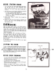
,., BEFORE STARTING ENGINE ! 1. Fill the fuel tank. with fresh winter blend regular gasoline. DO NOT MIX OIL WITH GASOLINE. Make certain the fuel shut-off valve under the gas tank is turned on. 2. Place machine on a level surface. Remove oil fill cap and fill crankcase with good quality detergent oil. Use MS classification SAE 5W-20 oil for operation below 400 F. Use MS classification SAE 30 oil for operation 3. During above 400 F. initial "Break-in" period, the oil should be checked often. 4.
OPERATION OF CONTROLS MASTER CLUTCH CONTROL The master Clutch control is located on handle panel and is used to engage all power. Select a forward speed or reverse with shift lever, then release master clutch control and push forward to engage drive disc, fan, reel. To disengage, pull master clutch control back and lock in notch. The master clutch control must always be in neutral position before starting engine.
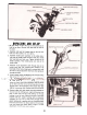
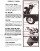
REPLACING SAFETY SHEAR BOLT If the intake snow reel should jam causing the safety shear bolt to shear, it may be replaced with a new bolt, furnished in the parts bag, after removing the broken pieces in the shaft. NOTE: Always align the hole in the reel shaft and the sprocket shaft before driving out the broken bolt. CHUTE CHAIN AND ADJUSTMENT To tighten the chute chain, rotate the chute all the way to the left, until the adjustment bolt is accessible. Tighten the adjustment nut to tighten the chain.
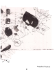
~ r oj /' ~ See pages10 and 11 for parts list.
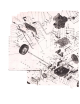
PARTS LIST MODEL 7100-1 Your SNOW THROWER is right hand (R.H.) or left hand (L.H.) as you operate mad1ine. REF. PART NO. NO. DESCRIPTIDN 1 2 3 4 5 6 7 8 9 10 11 12 13 14 15 16 17 18 19 20 21 22 23 24 25 26 27 28 1539-80 1658-29-40 41256 2119-49 3616-516 1538-30 40070 2643-51-40 1710-50-40 4712-99 1!.
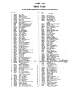
~. ~. : TRANSMISSION S '/" 7 8,9 /, ~. ., '0 , ~ I " 0&0., -- : o;..~~ )0' ~ ~/ ) '~ .~'l"~/20 '...~ ~-. ., .." ».- .. f , / 23 ~.';' 2K 22- . ~ / / ; ~'", ..I PARTS LIST REF. NO. 1 PART NO. 1654-31 2 3 4 1624-192 1652.114 1149-5 5 6 7 B 9 10 11 12 13 14 15 16 17 1B 19 20 42342 1008 1646-24 2638-51 1624-191 1632-177 2111.107 1538-30 101B 1657-60 40148 42373 3150-1 2676-9 1629-15 1509-00 DESCRIPTIDN REF. NO. 21 22 23 24 25 26 Chain -W/Connecting Link No. 41 x 28 pitd...
NOTE: Make all adjustments with the engine turned off and wire removed from the sparkplug. (Fasten wire to cylinder head at least ," away from sparkplug.) IDLER LINKAGE ADJUSTMENT Should the drive belt stretch sufficiently to cause the adjustment link to hang up in the bottom of the idler arm slot when the master clutch lever is in drive position, readjust as follows.
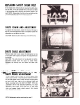
LUBRICATION CHANGINGENGINEOIL Drain oil when engine is warm. To drain oil, place pan under frame directly beneath oil drain access hole. Remove oil drain plug and allow oil to drain completely. Replace drain plug and tighten securely. Refill to "Full", approximately 1 pint. See engine manual for complete engine lubrication and service instructions. LUBRICATION POINTS lUBRICATE THE PARTS PERIODICAllY AS IllUS. TRATED.
5. 3. 4 CHUTE CABLE REPLACEMENT cable roller bracket and down to the right hole in the top of the blower housing. C. Turn the cable pulley with the cable bolt toward the bottom of the blower housing. OR REPAIR 1. REMOVE THE MACHINE. BLOWER HOUSING FROM THE A. Remove the chain guard and disconnect the reel drive chain at the chain connecting link. B. Remove the four carriage bolts, fastening the scoop to the mounting brackets. Remove the scoop and reel assembly intact.
~ 7171 M 26" SNOW THROWER We gu'arantee all parts again'st. defects' in material and workmanship year from the date of purchase when used for residential. 90 days .for a period of one for commercial. (1) :We agree tq repair or repla~e without charge to the original Purchaser, including labor, any part or parts upon examination 9Y a Yard-:Man Authorized Dealer to be defective within the guarantee period except the engine which is warranteed separately by the manufacturer.