7100 SERIES FIRE ALARM CONTROL INSTALLATION/OPERATING MANUAL Copyright © 1998 All Rights Reserved Published in U.S.A. Part Number: 9000-0447 Version 1.
IMPORTANT INFORMATION This manual is designed for use by factory trained installers and operators of the Fire Control Instruments, Inc. (FCI) 7100 Series Fire Alarm Control. All illustrations, functional descriptions, operating and installation procedures, and other relevant information are contained in this manual. The contents of this manual are important, and the manual must be kept with the fire alarm control panel at all times.
INSTALLATION CONSIDERATIONS: Check that you have all the equipment you need to make the installation. Follow the field wiring diagrams and installation notes in this manual. Install the equipment in a clean, dry environment (minimal dust). Avoid installing equipment where vibrations will occur. Remove all electronic assemblies prior to drilling, filing, reaming, or punching the enclosure.
FCC WARNING: This equipment generates, uses, and can radiate radio frequency energy and, if not installed and used in accordance with the instruction manual, may cause interference to radio communications. It has been tested and found to comply with the limits for Class A computing device pursuant to Subpart B of Part 15 of FCC Rules, which is designed to provide reasonable protection against such interference when operated in a commercial environment.
• • • Smoke detectors cannot be expected to provide adequate warning of fires caused by arson, children playing with matches (especially within bedrooms), smoking in bed, violent explosions (caused by escaping gas, improper storage of flammable materials, etc.). Heat detectors do not sense particles of combustion and are designed to alarm only when heat on their sensors increase at a predetermined rate or reaches a predetermined level. Heat detectors are designed to protect property, not life.
9000-0447 5 of 46
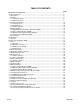
TABLE OF CONTENTS Page IMPORTANT INFORMATION.........................................................................................................1 1.0 System Overview .....................................................................................................................9 1.1 Description..............................................................................................................................9 1.2 Features ..................................................................
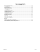
TABLE OF CONTENTS Continued 4.0 Programming/Operating...........................................................................................................26 4.1 LED Indicators ........................................................................................................................26 4.2 Panel Switches .......................................................................................................................27 5.0 System Programming............................................
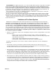
TB1 TB2 TB3 TB4 TB5 TB7 JMP1 TB6 8 of 46 BSM TB9 9000-0447
1.0 System Overview 1.1 Description The FCI 7100 is a multiprocessor-based analog/addressable fire alarm control panel, designed for commercial, industrial and institutional fire alarm applications. It is available with one or two signaling line circuits. The 7100 Series Fire Alarm Control is Listed by Underwriters Laboratories Standard UL 864.
1.3 Control and Indicators 1.3.1 Switch Controls • Alarm Acknowledge • Trouble Acknowledge • Signal Silence • System Reset/Lamp test • Programming buttons – Menu/Back – Back Space/Edit – OK • 12 button keypad 1.3.2 LED Indicators • AC Power On • Alarm • Supervisory • System Trouble • Power Fault (green) (red) (yellow) (yellow) (yellow) • • • • Ground Fault NAC 1Silenced NAC 2 Silenced System Silenced (yellow) (yellow) (yellow) (yellow) 1.3.
1.4.4 Printer Transient Module (PTRM) The serial output on the BSM is via an existing RS-232 RJ-11 connector, J3. This can be used to communicate to the control with a laptop computer while at the panel. The PTRM module is intended for systems where a permanent connection is required.
24 VDC power, system (TB4) Unregulated Resettable and non-resettable 1.0 amp. max. each circuit, 1.0 amp. max. combined Unsupervised Battery Connection (TB7) Supervised 24 VDC nominal Max. battery size 31 AH Non-power limited 0.6 A max. battery charge current The RS-232 port, consists of an RJ11 connector which provides a standard serial port for connection to a Listed output device for supplementary type service.
2.0 Installation 2.1 General The 7100 is shipped unassembled. The shipping carton contains an installation drawing, backbox, Basic System Module (BSM), power transformer and door. 1) Refer to the System Assembly Drawing, P/N 9000-0457. 2) The BSM module consists of a main operating board with pluggable terminal strips, an 80-character LCD display and programming keypad. Install this module immediately unless any option modules are to be used in the system.
Table 1a - LEDs, Jumpers Designation LEDs LED25 LED26 Description Comments Yellow Yellow Line 1 Trouble Line 2 Trouble Jumpers W1 W2 W3 W4 J6 JMP1 Not used OUT to disable battery IN - No Local Phone Line 1 IN - No Local Phone Line 2 Connection to keypad Cut for 240 VAC input operation 3.1 Power 3.1.
Table 2 Battery Standby Chart Qty Module BSM-1 BSM-2 BSM-1D Description Basic System Module, 1 SLC Basic System Module, 2 SLC Basic System Module, 1 SLC w/DACT BSM-2D Basic System Module, 2 SLC w/DACT PTRM Printer Transient Module CAOM Class A Option Module MCOM Municipal Circuit Option Module LCD-7100 Optional Remote Serial Annunc. LDM-7100 LED Driver Module INI-7100 Intelligent Network Interface Mod. Supv. Current 0.056 A 0.065 A Alarm Current 0.076 A 0.085 A 0.075 A 0.095 A 0.085 A 0.020 A 0.
3.3 Notification Appliance Circuits EOL The 7100 provides two (2) 24 VDC Class B, Style Y notification appliance circuits. Class A, Style Z operation is accomplished by adding the Class A Option (CAOM) Module. For use with any UL Listed notification appliance having a nominal operating voltage of 24 VDC. Wiring Instructions NAC 1 - TB1-1 (+), TB1-2 ( - ) NAC 2 - TB1-3 (+), TB1-4 ( - ) (Polarity markings indicate the polarity of the circuit in alarm condition). Use U.L.
9000-0447 17 of 46 CAOM-TB1 SLC NO. 1 BSM -TB1 ` 2 1 2 1 Figure 3 WIRING FROM BSM TERMINAL 2 AND CAOM TERMINAL 1 TO LAST M500X MODULE SHALL BE AS SHORT AS POSSIBLE AND RUN IN RIGID CONDUIT. NOTE: 3 (-) 4 (+) 3 (-) 4 (+) M500X 1 (-) 2 (+) 1 (-) 2 (+) M500X WIRING FROM BSM TERMINAL 1 AND CAOM TERMINAL 2 TO FIRST M500X MODULE SHALL BE AS SHORT AS POSSIBLE AND RUN IN RIGID CONDUIT.
NOTICE: USE ONLY THE LISTED AND APPROVED METHODS AND DEVICES REFERENCED IN THIS MANUAL TO ACTUATE A FIRE EXTINGUISHING SYSTEM. REFER TO THE INSTALLATION MANUAL FOR THE PROPER USE OF THE SYSTEM IN A PARTICULAR APPLICATION. EXTINGUISHING AGENTS THAT SUPPRESS FIRES BY OXYGEN DILUTION SUCH AS CARBON DIOXIDE AND VARIOUS INERT GASES SHALL BE PROVIDED WITH LISTED, APPROVED, MECHANICALLY OPERATED TIME DELAYS AND STOP VALVES TO CONTROL THE DISCHARGE TO A PROTECTED AREA.
This page was intentionally left blank.
3.5 Analog Sensors The 7100 accommodates only FCI approved, U.L. Listed, Factory Mutual Approved analog sensors and bases. See FCI Publication, P/N 9000-0427 for a list of approved sensors and bases. Each signaling line circuit can accommodate 99 sensor address points, using Address numbers 01 to 99. 3.5.1 Address Switches Addresses are set via the rotary switches on each sensor or module.
Table 3 Optional Module Wiring Connections CAOM Module Designation TB1-1 TB1-2 TB1-3 TB1-4 TB2-1 TB2-2 TB2-3 TB2-4 Description NAC1 NAC1 NAC2 NAC2 SLC1 SLC1 SLC2 SLC2 MCOM Module TB1-1 TB1-2 Jumpers W1 MCOM W2 MCOM PTRM Module Jumper W1 PTRM Comments NAC Circuit 1, Class A return (+) NAC Circuit 1, Class A return ( - ) NAC Circuit 2, Class A return (+) NAC Circuit 2, Class A return ( - ) SLC Circuit 1, Class A return (+) SLC Circuit 1, Class A return ( - ) SLC Circuit 2, Class A return (+) SLC Circui
3.11 Central Station Reporting UL Listed receivers compatible with the 7100 are listed in Table 4 below: Table 4 Manufacturer Silent Knight Receiver Model Model 9000† Silent Knight Model 9800/9500 Ademco Model 685 Sur-Gard (Ver. 1.
3.
3.14 Digital Communicator Before connecting the 7100-D to the public switched telephone network the installation of two (2) lines is necessary. The following information is provided if required by the local telephone company: Manufacturer: Fire Control Instruments, Inc. 16 Southwest Park Westwood, MA 02090 Product Model Number: 7100-D FCC Registration Number: 6KWUSA-34215-AL-T Ringer Equivalence: 0.5B 3.
3.18 Optional Accessories 3.18.1 LCD-7100 Serial Remote Annunciator The LCD-7100 Serial Remote Annunciator provides an 80-character display and function keys for “Alarm Acknowledge”, “Trouble Acknowledge”, “Signal Silence”, “System Reset/Lamp Test” and “System Drill Test”. The 80-character display shows all pertinent information except for menus.
4.0 Programming/Operation Instructions 4.1 LED Indicators Table 6 Designation AC Power On Alarm Supervisory Description (green) (red) (yellow) System Trouble Power Fault Ground Fault NAC 1Silenced (yellow) (yellow) (yellow) (yellow) NAC 2 Silenced (yellow) System Silenced (yellow) 26 of 46 Comments Lights to indicate presence of 120/240 VAC input.
4.2 Switches Table 7 Designation Alarm Acknowledge Trouble Acknowledge Signal Silence Lamp Test/Reset Menu/Back BKSP/Edit OK Alphanumeric Keys PK-625 Key Switch 9000-0447 Comments Silences the panel audible sounder. This must be pressed once for each Alarm condition present in the system. Silences the panel audible sounder. This must be pressed once for each Trouble or Supervisory condition present in the system. Press once and any outputs programmed as silenceable will be deactivated.
5.0 System Programming System programming can be performed either by front panel programming as shown below or via portable computer and the FCI Field Configuration Program. See the FCP Software Training Guide, P/N 9000-0456. 5.1 MAIN Menu selections 7100 MENU STRUCTURE MAIN CONFIG. where automatic configuration of the system is accomplished, as well as all of the system global programming, input to output group programming and NAC coding.
Main Any selection (Only opens if adequate access has not already been obtained) Main Config Password Main Config Inputs Type Edit (If BKSP/EDIT is pressed, and editing is possible.) Main Config Inputs Type Define Type (After response category is accepted) Main Config Inputs (or Outputs) Select Location Edit ———————— or ———————— Main Config System ID Edit Various (If OK is pressed when illegal value has been entered.
5.2 CONFIG. Menu Selections AUTO is the selection used to either initialize the system or update it. CONFIG. GLOBAL is the key feature to the simplicity of programming. Most system as well as individual SLC device programming can be accomplished here. INPUTS allow the user to insert point-to-point address information to sensors and monitor points individually for device type, location, input group(s), and to modify any of the global programming. AUTO GLOBAL OUTPUTS the inputs.
7100 Series Menu System Menu Tree Main Main Config Display and Selections [MAIN] 1:Config 2:Walk/Drill 3:I/O 4:Clock 5:View 6:Log 7:Info 1: Opens System Config Menu (PW-L4 required) 2: Opens Walk Test / Drill Menu (PW-L1 required) 3: Opens I/O Control Menu (PW-L2 required) 4: Opens Set Clock Menu (PW-L1 required) 5: Opens System Config Menu for viewing only (PW-L3 required) 6: Opens Event Log Menu (PW-L1 required) Note: View option is identical to the Config option, allowing access to all the configuratio
Main Config Global Device defaults Main Global ConfigDevice defaults Default Verification Main Config Global Device defaults Default Sensitivity Main Config Global Device defaults PAS Parameters [SET ] 1:Verification 2:Sensitivity [DEFAULTS] 3:PAS 4:Multilevel 1: Opens Set Default Verify Options menu. 2: Opens Set Default Sensitivity Menu. 3: Opens Set PAS Parameters menu. 4: Opens Set Multilevel Parameters menu.
Main Config Global Codes Main Config Global System ID or Main Config Inputs (or Outputs) Select Location [CODED] 1:Set Day Alarm (MT60) Config [PATTS] to select condition <>: selects response condition from: Day Alarm, Night Alarm, Action, Supervisory, Tornado. 1: Scrolls through coded pattern selections: MT60, MT120, Temporal, CA Code, Coded 4s. [L,AAA] [LOCTN] FLR1 Lobby Config 7,9 chng 1st ^ chng 2nd Enter label using keypad and shift key. Press button until desired letter appears.
Main Config Inputs or Outputs ——————— or ——————Main I/O Control or Ena/Dis [SELECT] Loop,Address: 1,001 [DEVICE] Key in or use <,> # keys: enters loop & address (restriction: Address 200) < >: Scrolls up or down to next available device. OK: Accepts address, opens Configure Input Device Menu, Configure Output Device Menu, Control Output Menu, or Enable/Disable Device Menu, as appropriate.
Main Config Outputs Select Main Config Outputs Select Type [CONFIG] 1:Type 2:General Resp 3:Groups [L,AAA ] 5:Location 6:View 7:Copy L,AAA 1: Opens Set Output Type Menu. 2: Opens Assign Output To Group(s) Menu. 3,4: Unused. 5: Opens Set SLC Device Location Menu. 6: Displays all settings for this device. 7: Copies settings of the specified device (last output modified).
Main Config DACT (opens only if DACT is installed) [CONFG] 0:Options 1:Line1 2:Line2 [DACT] 3:Account1 4:Account 2 0: Opens DACT Options menu. 1: Opens Phone Line Options menu for Line 1. 2: Opens Phone Line Options menu for Line 2. 3: Opens Account Options menu for Account 1. 4: Opens Account Options menu for Account 2. Main Config DACT Account Options [ACCTn] 1:Format 2:Reporting [OPTS ] 3:AccountID 4:CIC & Phone# 1: Opens Communications Format menu Account n.
5.3 WALK / DRILL Menu Selection Drill ON/OFF them. Is a simple ON or OFF selection. ON will activate the NACs, while OFF will deactivate Audible Test Is a simple ON or OFF selection for an audible walk test. The NACs will sound twice for a trouble, 3 times for a supervisory signal and 4 times for an alarm. WALK / DRILL DRILL ON/OFF AUDBL TEST SILENT TEST 5.4 I/O Menu Selection Output ON/OFF forces the toggling on or off of a specified output. These outputs can include NAC 1, NAC 2, Muni. Ckt.
Main Walk/Drill [Walk/] 1:Drill (OFF) 2:Audbl Test [DRILL] 3:Silent Test (OFF) 1: Toggles Fire Drill ON/OFF. 2: Toggles Audible Walk Test ON/OFF. 3: Toggles Silent Walk Test ON/OFF. Main I/O [I/O ] 1: Output On/Off [CTRL] 2: Enable/Disable Device 1: Opens Select Device to Control menu. 2: Opens Select Device to Enable menu. Note: These are the same menus as used in the Configure section, or similar, except after selection they proceed to the following menus.
5.5 CLOCK Menu Selection Time is set in 24 hour notation. It is set with hours then minutes “HHMM”. Date is set as month, date and year “MMDDYY”. Night Hours sets the Day/Night programming. If no time is set here the system will always remain in the Day mode. Night Start will initiate the Night/Weekend programming which is generally used to make certain sensors more sensitive to particles of combustion than during the day. This must be programmed in 24 hour notation (HHMM).
Main Clock Main Clock Time [SET ] 1:Time 2:Date 3:Night [CLOCK] 4:Weekend 5:Holidays 1: Opens Set Time menu. 2: Opens Set Date menu. 3: Opens Set Night Hours menu. 4: Opens Set Weekend Days menu. 5: Opens Set Holiday Schedule menu. [SET ] 13:44 (1:44 PM) [TIME] Type HHMM (24-hour notation) keypad: enter time. Main Clock Date [SET ] 07/16/98 (Thu July 16, 1998) [DATE] Type MMDDYY keypad: enter date.
5.6 LOG Menu Selection Display Log Opens the System Display to all events in the buffer memory. Print Log Sends the entire buffer memory to the RS-232 port. Clear Log (Hard reset) will eliminate all events stored in the buffer memory. Sensitivity Report Will send sensor sensitivity information to the RS-232 port. LOG DISPLAY LOG PRINT LOG ` CLEAR LOG SENSITIVITY REPORT 5.7 INFO Menu Selection Displays the Firmware Version installed in the 7100.
Main Log [VIEW] 1:Display Log 2:Print Log [LOG ] 3:Clear Log 4:Sens. Report 1: Opens Show Events menu. 2: Opens Print Log menu. 3: Prompts for OK; if accepted, clears the event log and resets the panel. 4: Initiates a sensor sensitivity printout. Main Log (Display shows a log entry) Show Events Main Log Print Log Main Info 42 of 46 Scrolls through all logged events, beginning with the most recent event.
6.0 Power Up Procedure 6.1. General Ensure that all cables and optional modules (if any) are installed and secured per the installation instructions. DO NOT install any field wiring at this time. Connect the End of Line devices to the notification appliance and municipal (if installed) circuits. 2. Power the panel with AC first. The system will initialize and indicate a “Battery Missing” condition. 3. Connect the batteries, taking care to observe polarity. 4. The system should be in normal condition.
7100 Series Device Types and Functions 44 of 46 9000-0447
Typical Wiring - DRBC-1 to 7100 9000-0447 45 of 44
Knockouts for Non Power-Limited wiring. This includes 120/240 VAC, Batteries (if remote from enclosure, DACT (optional) and Municipal (optional) Wiring. All Power-Limited Wiring Municipal Circuit Reverse Polarity Application. PowerLimited Municipal Circuit Local Energy Master Box/Releasing Application, Route under PCB. Non Power-Limited. 120/240 VAC wiring. Non Power-Limited DACT wiring. Non Power-Limited Battery wiring.
16 Southwest Park, Westwood, MA 02090 USA TEL: (781) 471-3000 FAX: (781) 471-3099