'r .I / f ~ ~ MAN CO.. -- 1410 West Ganson Street PRINTED !N U.S.A. "Iand ~ YARD. P. O.
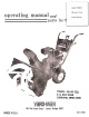
Your SNOW THROWER is a precision piece of snow throwing equipment. Engineering skill and experience have been combined to provide the ultimate in safety and efficiency. As with any type of power equipment, carelessnessor error on the part of the operator can result in injury. EXERCISE EXTREME CAUTION AT ALL TIMES. 2. 3. 4. 5. 6. 7. 8. 9. a. Replace c. 10. 1.. READ THE OWNER'S MANUAL CAREFULLY. Know the controls to operate your SNOW THROWER properly and how to quickly stop th~unit.
CE~ FREE OPERATION , GENERAL SNOW~THROWING 1.~ Always keep area to be cleaned cleared before~owfall~. . 2.~. Always start engine with machine on level surface ';;;..""i" with '-. master clutch disengaged: After starting, let engine warm up several minutes at slow speed before starting to remove ~now~ Ifinachine is stored indoors, let engine and machine adjust to outdoor temperatures before starting to throw snow': ... ..'co 3. When throwing snow, ~u!:,machln.eat.~ull throttl~ for best re~lts: .4.
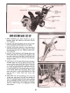
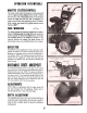
AND SET-UP 1. Before assembling your Snow Thrower be sure all hardware, parts, and instructions have been removed from the carton. , ...:' ':;.' '-2. Assemble right and left handle tubes to the unit with bolts, lockwashers, and flat washers. Do not tighten.3. Assemble handle panel assembly to the under side of right and left handle tubes and secure with four slotted hex head bolts and lock nuts. Tighten all bolts on the handle assembly.4.
BEFORE STARTING ENGINE 1. Fill the fuel tank with fresh winter blend regular gasoline. DO NOT MIX OIL WITH GASOLINE. Make certain the fuel shut-off valve under the gas tank is turned on. 2. Place machine on a level surface. Remove oil fill cap and fill crankcase with good quality detergent oil. Use MS classification SAE 5W-20 oil for operation below 400F. Use MS classific:atio~ SAE 30 oil for operation above 400F. 3. During initial "Break-in" period, the oil should be checked often. . 4.
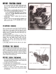
OPERATION OF CONTROLS MASTERCLUrCH CONTROL The master clutch control is located on handle panel and IS used to engage, all 'power~Select:8 forward speed or rever~ " ",,'c,';""...c"":, with shift lever, then release master clutch control ,.and- push , '.. c, ,," f,orward to engage ?rive diS?: f~~: reel. To disengage, puII master clutch control back and" lock in ' notch. The master ." , ,,'.. clutch control must always'beln: neutral position before -, '~-""'" ,.' -' -' ":!, , . starting engine,;"'~ "'..
. To . REPLACING SAFETY SHEAR BOLT If the intake snow reel should jam causing the safety shear bolt to shear, it may be replaced with a new bolt, furnished in the parts bag, after removing the broken pieces in the shaft. NOTE: Always align the hole in the reel shaft and the sprocket shaft before driving out the broken bolt. Do NOT remove solid pin located near shear bolt hole.
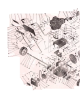
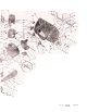
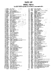
PARTS LIST MODEL 7200-0 Your SNOW THROWER is right hand (R.H.I or left hand (L.H.I as you operate machine. 1 2 :I 4 6 6 7 8 9 10 11 12 13 14 16 16 17 18 19 20 21 22 23 24 25 26 27 28 29 30 31 32 33 34 35 36 37 38 39 40 41 42 43 44 45 46 47 48 49 50 51 52 53 54 55 56 57 48 59 60 61 64 65 66 68 69 70 71 72 73 74 75 76 77 78 79 80 81 82 83 84 85 86 87 88 89 90 91 92 93 94 95 96 97 98 99 100 101 102 103 104 1539-80 1658-29-40 41256 2119-4b Nut -Push 1/2 Roller -Crenk Wa,her-S.A,E, 1/2 A...
-8 PARTS LIST REF. PART NO. NO. t 1654-31 2 -3 4 1624-192 1652-114 1149-5 .6 6 7 a 9 10 11 12 13 14 15 16 17 18 20 21 42342 1008 1646-24 2638-51 1624-191 1632.177 2111.107 1538-30 1018 1657-60 40148 42373 3150-20 2675.26 1509.90 2632.175 DESCRIPTION Chain -W/Connactlng Link No.41 x 28 pitches Spacer-Gear Sprocket Baaring-Needla7/16x 1/2 L. A-mbly -Gaar & Sprocket W/Bearlng (Included Ref. No.3) Nut -Hex Lock 3/8.16 (Eslok) Washer-SA.E.
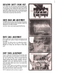
NOTE: Make all adjustments ..., with the engine turned off and wire removed from th~- sparkplug. (Fasten wire to II .., cylinder head at least 1 away.from sparkplug.) IDLER LINKAGE ADJUSTMENT .:.~. :a~.!...L:. ~ Should the drive belt stretch enough to prevent the ad justment link from moving freely in the idler arm, slot, with the master clutch lever in drive position, adjust' as follows. With master clutch in drive position, remove cotter pin .~ from adjustment link.
LUBRICATION- CHANGING ENGINE OIL Drain oil when engine is warm. To drain oil, place pan under frame directly beneath oil drain extension. Remove oil drain cap and allow oil to drain completely. Replace drain cap and tighten securely. Refill to "Full", approximately 1 pint. See engine manual for complete engine lub. rication and service instructions. LUBRICATIONPOINTS lUBRICATE THE PARTS PERIODICAllY AS IllUS-TRATED.
cable roller bracket and down to the right hole in the top of the blower housing. CHUTE CABLE REPLACEMENT OR REPAIR 1. REMOVE THE MACHINE. C. Turn the cable pulley with the cable bolt toward the bottom of , the blower housing. , " .'\ ' . BLOWER HOUSIN~ D. Put the ends of the cable up through the holes in the bottom of the cable pulley and cross the ends up and over the cable bolt and under the washer.
1~ .
30" SNOW THROWERyou enjoy these outstanding features ~ 7/73