
Operator`s manual


Model7L3
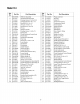
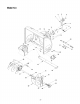
Ref.
Part No.
No.
1. 712-0116
2. 756-0178
3. 784-5632B
4. 710-0459A
5. 738-0281
6. 736-0174
7. 732-0611
8. 712-3068
11. 05931A
12. 741-0309
13. 710-0451
14. 705-5226
15. 684-04129
16. 712-04063
21. 731-2635
22. 731-2643
Ref.
Part Description No. Part No.
Lock Jam Nut 3/8-24 24. 790-00087
Flat Idler 26. 710-0726
Auger Idler Arm 27. 725-0157
Hex Cap Screw 3/8-24 x 1.50 28. 712-04065
Shoulder Screw 29. 741-0245
Wave Washer 30. 784-5580
Extension Spring 33. 790-00118
Hex Nut 5/16-18 34. 710-0451
Housing 35. 684-0065
Ball Bearing 36. 715-0114
Carriage Bolt, 5/16-18 x.75 37. 618-0122B
Chute Reinforcement 38. 605-5196A
Auger Housing Assembly 28" 39. 736-0188
Flange Lock Nut 5/16-18 40. 741-0493A
Clean-Out Tool Mount 41. 605-5197A
Clean-Out Tool 42. 710-0890A
Part Description
Bearing Housing
Hex Screw 5/16-12
Cable Tie
Flange Lock Nut 3/8-16
Hex Flange Bearing
Skid Shoe
Shave Plate
Carriage Bolt 5/16-18 x 1.00
Impeller Assembly
Pin
Gear Assembly Complete, 28"
Spiral Assembly RH
Flat Washer
Flange Bushing
Spiral Assembly LH
Shear Bolt 5/16-18 x 1.5
NOTE: For painted parts, please refer to
the list of color codes below. Please add
the applicable color code, wherever
needed, to the part number to order a
replacement part. For instance, if a part
numbered 700-xxxx is painted Yard-Man
Green, the part number to order would be
700-xxxx-0665.
Yard-Man Green: 0665
Yard-Man Yellow: 0674
Powder Black: 0637
21