Operator’s Manual Snow Thrower Models E643E E663H IMPORTANT: READ SAFETY RULES AND INSTRUCTIONS CAREFULLY Warning: This unit is equipped with an internal combustion engine and should not be used on or near any unimproved forest-covered, brushcovered or grass-covered land unless the engine’s exhaust system is equipped with a spark arrester meeting applicable local or state laws (if any). If a spark arrester is used, it should be maintained in effective working order by the operator.
TABLE OF CONTENTS Content Page Important Safe Operation Practices ........................................................................ 3 Loose Parts ............................................................................................................. 5 Assembling Your Snow Thrower ............................................................................. 5 Know Your Snow Thrower.......................................................................................
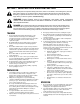
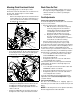
SECTION 1: IMPORTANT SAFE OPERATION PRACTICES This symbol points out important safety instructions, which if not followed, could endanger the personal safety and/or property of yourself and others. Read and follow all instructions in this manual before attempting to operate this machine. Failure to comply with these instructions may result in personal injury. When you see this symbol—heed its warning.
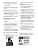
. 5. 6. 7. 8. 9. 10. 11. 12. 13. 14. 15. 16. 17. 18. 19. 20. Never operate with a missing or damaged discharge chute. Keep all safety devices in place and working. Never run an engine indoors or in a poorly ventilated area. Engine exhaust contains carbon monoxide, an odorless and deadly gas. Do not operate machine while under the influence of alcohol or drugs. Muffler and engine become hot and can cause a burn. Do not touch. Exercise extreme caution when operating on or crossing gravel surfaces.
SECTION 2: LOOSE PARTS The snow thrower is shipped with following loose parts in the carton. Please remove all loose parts from the carton before discarding it. See Figure 1 to identify the parts noting that these parts may be referred to again in the following sections of this manual. Part numbers are shown in parentheses. Shear Bolts (710-0890A) Hex Lock Nuts (712-0429) AUGER SHEAR BOLTS The augers are secured to the auger shaft with two shear bolts and hex lock nuts.
Attaching Chute Directional Control Chute Clean-Out Tool For packaging purposes, the two-piece chute directional control was attached to the snow thrower on the two ends, but was kept loose at the middle. Assemble as follows: • • Final Adjustments Remove the hairpin clip from the chute directional control. Align holes on the upper and lower pieces of the chute directional control before reinserting the hairpin clip. See Figure 4.
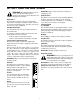
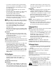
SECTION 4: KNOW YOUR SNOW THROWER WARNING: Be familiar with all the controls IMPORTANT: Always release tractional control before on the snow thrower and their proper operation. Know how to stop the machine and disengage them quickly. changing speeds. Chute Tilt Control The distance snow is thrown can be varied by adjusting the pitch of the chute assembly. Move the chute tilt control forward to decrease the distance, or toward the rear to increase the distance. See Figure 6.
Traction/Auger Control Lock Shift Lever Chute Tilt Control Fuel Shut-Off Valve (If So Equipped) Closed Auger Control Open Discharge Chute Chute Clean-Out Tool Chute Directional Control Primer Choke Ignition Key Throttle Control Auger Rope Starter Handle Figure 6 SECTION 5: OPERATING YOUR SNOW THROWER Before Starting WARNING: Read, understand, and follow • all instructions and warnings on the machine and in this manual before operating.
• • • • • • starter will not harm engine or starter. Disconnect the power cord from receptacle first, and then from snow thrower’s switch box. If your home electrical system is grounded, but a three-hole receptacle is not available, one should be installed by a licensed electrician before using the electric starter. If you have a grounded three-prong receptacle, proceed as follows: Connect power cord to switch box on engine.
• • • • • • In a well-ventilated area, start the snow thrower engine as instructed earlier in this section under the heading Starting Engine. Make sure the throttle is set in the FAST position. While standing in the operator’s position (behind the snow thrower) engage the auger. Allow the auger to remain engaged for approximately ten (10) seconds before releasing the auger control. Repeat this several times.
Operating Tips • NOTE: Allow the engine to warm up for a few minutes as the engine will not develop full power until it reaches operating temperature. • • • • WARNING: Muffler, engine and surrounding areas become hot and can cause a burn. Do not touch. • Set the skid shoes 1/4" below the shave plate for normal usage. The skid shoes may be adjusted upward (to lower the shave plate) for hard-packed snow. Adjust downward (to raise the shave plate) when using on gravel or crushed rock.
Shift Rod Adjustment • To adjust the shift rod, proceed as follows. • • • • • Remove the hairpin clip and slide the connector up to separate the upper shift rod from the lower shift rod. See Figure 11. Place shift lever in the sixth (6) Forward position. Rotate the shift arm counterclockwise (from the operator’s position) as far as it will go. Thread the upper shift rod downward until the elbow on its lower end aligns with the hole found in the lower shift rod.
SECTION 7: MAINTAINING YOUR SNOW THROWER Lubrication Drive and Shifting Mechanism At least once a season or after every 25 hours of operation, remove rear cover. Lubricate any chains, sprockets, gears, bearings, shafts, and shifting mechanism at least once a season. Use engine oil or a spray lubricant. WARNING: Before lubricating, repairing, or inspecting, disengage all clutch levers and stop engine. Wait until all moving parts have come to a complete stop.
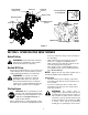
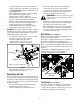
Shave Plate and Skid Shoes • The shave plate and skid shoes on the bottom of the snow thrower are subject to wear. They should be checked periodically and replaced when necessary. To remove the skid shoes, proceed as follows: • • • Back out the stop bolt until the support bracket rests on the auger pulley. See Figure 18. NOTE: Loosening the six nuts that connect the frame to the auger housing may aid in belt removal.
• • Slip belt between friction wheel and friction wheel disc. See Figure 18. Remove and replace belt. • Friction Wheel • Drive Plate • Stop Bolt • • Support Bracket Remove six self-tapping screws from the frame cover underneath the snow thrower. Remove the click pins which secure the wheels, and remove the wheels from the axle. Using a 7/8" wrench to hold the shaft, loosen, but do not completely remove, the hex nut and bell washer on the left end of gear shaft. See Figure 18.
Off-season Storage • • WARNING: Never store the machine or fuel container indoors where there is an open flame, spark or pilot light such as on a water heater, furnace, clothes dryer or other gas appliances. • If unit is to be stored over 30 days, prepare for storage as follows: • • • Drain carburetor by pressing upward on bowl drain, located below the carburetor cover. Remove all dirt from exterior of engine and equipment.
SECTION 9: TROUBLESHOOTING Problem Cause Remedy Engine fails to start 1. Fuel tank empty, or stale fuel present in gas 1. Fill tank with clean, fresh gasoline. Fuel becomes stale after thirty days tank. unless a fuel stabilizer is used. 2. Clean the fuel line. 2. Blocked fuel line. 3. Move switch to ON position 3. Choke not in ON position 4. Clean, adjust gap or replace. 4. Faulty spark plug. 5. Safety key not in ignition switch on engine. 5. Insert the key fully into the switch. 6.
SECTION 10: MODEL E663H & E643E PARTS LIST 27 20 39 38 Drive Clutch Cable 37 5 13 52 Auger Clutch Cable 4 30 7 6 40 3 4 30 2 14 26 15 5 36 16 44 51 7 31 28 23 10 12 17 41 18 24 32 9 11* 25 8 4 1 22 33 29 8 21 1 20 42 5 34 Auger Clutch Cable 43 35 46 45 48 1 49 49 50 47 * Add a second washer here, if needed, to reduce axle play.
Models E663H & E643E Ref. No. Part No. Part Description Ref. No. Part No. Part Description 1 710-1652 Self-tapping Screw, 1/4-20 x .625 29 684-0013B Wheel Shift Rod Assembly 2 784-5688 Drive Cable Guide Bracket 30 710-0599 Self-tapping Screw, 1/4-20 x .
Models E663H & E643E 2 3 1 4 44 5 43 11 10 9 15 18 14 12 7 6 8 13 9 18 19 20 16 22 23 27 34 21 10 28 13 25 23 18 13 38 26 31 35 22 30 18 32 31 33 16 41 37 36 17 39 40 29 40 42 39 20 24
Models E663H & E643E Ref. No. Part No. Ref. No. Part Description Part No. Part Description 1. 712-0116 Lock Jam Nut 3/8-24 25. 710-0703 2. 756-0178 Flat Idler, 2.75 w/o Flanges 26. 710-0726 Hex Screw 5/16-18 x .75 3. 784-5632B Auger Idler Arm 27. 736-0169 Lock Washer 3/8 4. 710-0459A Hex Cap Screw 3/8-24 x 1.50 28. 712-0798 Hex Nut 3/8-16 5. 738-0281 Shoulder Screw 29. 741-0245 Hex Flange Bearing 6. 736-0167 Flat Washer 30. 784-5580 Skid Shoe 7.
Models E663H & E643E 1 2 3 8 9 11 13 5 4 27 10 12 15 16 4 7 16 6 20 22 20 14 18 23 17 26 19 24 21 25 21 22
Models E663H & E643E Ref. No. Part No. Part Description 1. 710-1652 Hex Washer Screw 1/4-20 x.625 2. 731-1324 Belt Cover 3. 732-0710 Extension Spring 4. 710-0627 Hex Screw 5/16-24 x .75 5. 710-3005 Hex Cap Screw 3/8-16 x 1.25 6. 05896A Drive Clutch Bracket 7. 748-0234 Shoulder Spacer 8. 756-0987 Pulley Half 9. 754-0346 V-Belt 10. 756-0986 Pulley Half 11. 736-0270 Bell Washer 12. 710-0230 Hex Cap Screw 1/4-28 x .50 13. 756-0313 Flat Idler 14.
Models E663H & E643E 67 70 73 10 3 13 44 32 32 38 68 45 33 49 55 32 3 32 39 19 45 72 51 41 42 46 36 35 48 43 4 18 34 30 ground wire 71 (for of light ass’y) 41 54 62 47 27 39 40 55 37 5 11 43 A 20 31 12 55 76 23 29 B 8 B A 25 28 22 21 35 24 59 6 78 1 26 52 4 20 12 54 41 58 61 74 56 75 12 57 17 8 24 16 14 15 60 76 53 66 9 63 65 42 59 55 64 44 69 7 2
Models E663H & E643E Ref. No. Part No. Ref. No. Part Description Part No. Part Description 1. 684-0008A Shift Arm Assembly 40. 736-0105 2. 684-0053B Lower Chute Crank Assembly 41. 736-0119 Lock Washer, 5/16 3. 714-0507 Cotter Pin, 3/32 x .75 42. 736-0509 Special Washer, .35 x .72 x .13 4. 710-0458 Carriage Bolt, 5/16-18 x 1.75 43. 746-0778 Cable “Z” Fitting 5. 710-0449 Carriage Bolt, 5/16-18 x 2.25 44. 747-0877 Cam Rod 6. 710-0788 Self Tapping Screw, 1/4-20 x 1 45.
Models E663H & E643E 4 17 11 9 16 13 8 15 1 10 14 5 6 3 7 12 3 2 Ref. No. Part No. Part Description 1. 618-0123 RH Housing 2. 618-0124 LH Housing w/Fitting Hole 3. 710-0642 Self Tapping Screw, 1/4-20 x .75 4. 711-1024A Spiral Axle, 30” (E663H) 711-0908A Spiral Axle, 24” (E643E) 5. 714-0161 Hi-Pro Key, 3/16 x 5/8 6. 715-0143 Spring Spirol Pin, .25 x 1.25 7. 717-0528A Worm Gear, 20-tooth 8. 717-0526 Worm Shaft 9. 718-0186 Thrust Collar 10. 721-0325 Grease Plug 11.
NOTES 27
MANUFACTURER’S LIMITED WARRANTY FOR: The limited warranty set forth below is given by MTD LLC with respect to new merchandise purchased and used in the United States, its possessions and territories. MTD LLC warrants this product against defects for a period of two (2) years commencing on the date of original purchase and will, at its option, repair or replace, free of charge, any part found to be defective in materials or workmanship.