Operator’s Manual LT31 2-Cycle Petrol Trimmer IMPORTANT: Read safety rules and instructions carefully before operating equipment. PRINTED IN U.S.A. PART NO.
TABLE OF CONTENTS Content Page Important Safe Operation Practices............................................................... 3 Know Your Trimmer ........................................................................................ 6 Assembling Your Trimmer............................................................................... 7 Operating Your Trimmer.................................................................................. 8 Maintaining Your Trimmer .................................
SECTION 1: IMPORTANT SAFE OPERATION PRACTICES This Symbol Points Out Important Safety Information Which, If Not Followed, Could Endanger The Personal Safety And/or Property Of Yourself And Others. Read And Follow All Instructions In This Manual Before Attempting To Operate Your Cultivator. FailureTo Comply With These Instructions May Result In Personal Injury. When You See This Symbol–Heed Its Warning. SAFETY ALERT SYMBOL: Indicates danger, warning, or caution.
• WHILE OPERATING • • • • • • • • • • • • • • Never start or run the unit inside a closed room or building. Breathing exhaust fumes can kill. Operate this unit only in a well ventilated area outdoors. Wear safety glasses or goggles and ear/hearing protection when operating this unit. Wear a face or dust mask if the operation is dusty. Wear heavy, long pants, boots, gloves and a long sleeve shirt. Do not wear loose clothing, jewelry, short pants, sandals or go barefoot.
SAFETY AND INTERNATIONAL SYMBOLS This operator's manual describes safety and international symbols and pictographs that may appear on this product. Read the operator's manual for complete safety, assembly, operating and maintenance and repair information. SYMBOL SYMBOL MEANING MEANING • THROWN OBJECTS CAN CAUSE SEVERE INJURY • SAFETY ALERT SYMBOL Indicates danger, warning or caution. May be used in conjunction with other symbols or pictographs. WARNING: Keep clear of blower outlet.
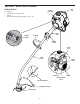
SECTION 2: KNOW YOUR TRIMMER APPLICATIONS As a trimmer: • • • Fuel Cap Starter Rope Grip Cutting grass and light weeds Edging Decorative trimming around trees, fences, etc.
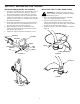
SECTION 3: ASSEMBLING YOUR TRIMMER INSTALLING AND ADJUSTING THE D-HANDLE INSTALLING THE CUTTING HEAD GUARD 1. Push the D-handle down onto the shaft tube so that the handle slants towards the shaft grip, Figure 1. The squared bolt hole in the handle is to the right. 2. Insert the shoulder bolt into the squared hole in the handle. Place the washer on the bolt, and screw the wing nut onto the bolt. Do not tighten until you make the handle adjustment. 3.
SECTION 4: OPERATING YOUR TRIMMER Thoroughly mix the proper ratio of 2-cycle engine oil with unleaded petrol in a separate petrol can. Use a 40:1 petrol/oil ratio. Do not mix them directly in the engine fuel tank. See the table below for specific petrol and oil mixing ratios. OIL AND PETROL MIXING INSTRUCTIONS Old and/or improperly mixed fuel is the main reason for improper unit performance. Be sure to use fresh, clean unleaded petrol. Follow the instructions carefully for the proper petrol/oil mixture.
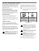
STARTING INSTRUCTIONS WARNING: Operate this unit only in a well ventilated outdoor area. Carbon monoxide exhaust fumes can be lethal in a confined area. Start/On (I) WARNING: Avoid accidental starting. Make sure you are in the starting position when pulling the starter rope, Figure 7. To avoid serious injury, the operator and unit must be in a stable position while starting. Ignition Switch Stop/Off (O) FIGURE 5 Position 2 1. Mix petrol with oil. Fill fuel tank with petrol/oil mixture.
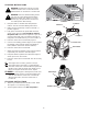
HOLDING THE TRIMMER For best results, tap the Bump Head™ on bare ground or hard soil. If line release is attempted in tall grass, the engine may stall. Always keep the trimming line fully extended. Line release becomes more difficult as the cutting line becomes shorter. WARNING: Always wear eye, hearing, foot and body protection to reduce the risk of injury when operating this unit. NOTE: Before using the unit, stand in the operating position, Figure 8.
SECTION 5: MAINTAINING YOUR TRIMMER NOTE: Some maintenance procedures may require special tools or skills. If you are unsure about these procedures take your unit to an authorized service dealer. NOTE: Maintenance, Replacement, or Repair of the emission control devices and system may be performed by any non-road engine repair establishment, individual or authorized service dealer.
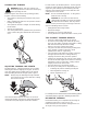
NOTE: Split-Line™ can only be used with the inner reel containing the slotted holes. Single line can be used on either type of inner reel. Use Figure 15 to identify the inner reel you have. NOTE: Always use the correct line length when installing trimming line on the unit. The line may not release properly if the line is too long. Loop FIGURE 18 Slotted Holes 10. Before winding, split the line back about 6 inches. 11. Wind the line in tight even layers in the direction indicated on the inner reel.
Clean and re-oil the air filter every 10 hours of operation. It is an important item to maintain. Failure to maintain the air filter will VOID the warranty. INSTALLING A PREWOUND REEL 1. Hold the outer spool with one hand and unscrew the bump knob counterclockwise, Figure 11. Inspect the bolt inside the bump knob to make sure it moves freely. Replace the bump knob if damaged. 2. Remove the old inner reel from the outer spool, Figure 12. 3. Remove the spring from the old inner reel, Figure 12. 4.
Checking the fuel mixture, cleaning the air filter, and adjusting the idle speed should solve most engine problems. If not and: CARBURETOR ADJUSTMENT The idle speed of the engine is adjustable through the air filter/muffler cover, Figure 26. NOTE: Careless adjustments can seriously damage your unit. An authorized service dealer should make carburetor adjustments.
SPARK ARRESTOR MAINTENANCE Spark Arrestor 1. Remove air filter/muffler cover. Refer to Removing the Air Filter/Muffler Cover. Flatblade Screwdriver 2. Locate muffler front and the two (2) bolts securing it to the engine, Figure 28. Remove the two (2) bolts using a flatblade screwdriver or 5/16-inch socket or nut driver. Pull muffler off of the engine. 3. Turn muffler over to the back side and locate the exhaust gasket. Remove the muffler exhaust gasket from the muffler, Figure 28.
SECTION 6: OFF SEASON STORAGE CLEANING THE UNIT LONG TERM STORAGE If the unit will be stored for an extended time, 1. Drain all fuel from the fuel tank into a container. Do not use fuel that has been stored for more than 60 days. Dispose of the old fuel in accordance to local regulations. 2. Start the engine and allow it to run until it stalls. This ensures that all fuel has been drained from the carburettor. 3. Allow the engine to cool. Remove the spark plug and put 30 ml. (1 oz.
SECTION 7: TROUBLE SHOOTING GUIDE ENGINE WILL NOT START CAUSE ACTION Empty fuel tank . . . . . . . . . . . . . . . . . . . . . . . . . . . . . . . .Fill fuel tank with properly mixed fuel Primer bulb wasn't pressed enough . . . . . . . . . . . . . . . .Press primer bulb fully and slowly 10 times Engine flooded . . . . . . . . . . . . . . . . . . . . . . . . . . . . . . . . .Use starting procedure with choke lever in the RUN position Old or improperly mixed fuel . . . . . . . . . . . . . . . . . . . . . .
SECTION 8: SPECIFICATIONS ENGINE* Engine Type . . . . . . . . . . . . . . . . . . . . . . . . . . . . . . . . . . . . . . . . . . . . . . . . . . . . . . . . . . . . . . . . . . . . . . Air-Cooled, 2-Cycle Stroke . . . . . . . . . . . . . . . . . . . . . . . . . . . . . . . . . . . . . . . . . . . . . . . . . . . . . . . . . . . . . . . . . . . . . . . . . . 31.75 mm (1.25 in.) Displacement . . . . . . . . . . . . . . . . . . . . . . . . . . . . . . . . . . . . . . . . . . . . . . . . . . . . . . . . . . .
SECTION 9: NOTES 19
SECTION 9: NOTES Cont... OPERATOR’S MANUAL PART NO.