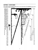
YaRD-MaN OPERATOR'S MANUAL 22" String Trimmer Mower Model Number 25A-253N401 IMPORTANT: Warning: READ SAFETY This unit is equipped RULES AND INSTRUCTIONS CAREFULLY with an internal combustion engine and should not be used on or near any unimproved forest- covered, brush-covered or grass-covered land unless the engine's exhaust system is equipped with a spark arrester meeting applicable local or state laws (if any).
TABLE OF CONTENTS Content Page Important Safe Operation Practices ................................................................... 3 Slope Gauge ...................................................................................................... 6 Assembling Your String Trimmer Mower ............................................................ 7 Know Your String Trimmer Mower .....................................................................
SECTION1: IMPORTANTSAFEOPERATION PRACTICES WARNING: This symbol points out important safety instructions which, if not followed, could endanger the personal safety and/or property of yourself and others. Read and follow all instructions in this manual before attempting to operate this machine. Failure to comply with these instructions may result in personal injury. When you see this symbol - heed Its warning.
• Shut the engine off and wait until the trimmer head comes to a complete stop before replacing trimmer line, making any adjustment or repairs. The trimmer head continuesto rotate for a few secondsafter the engine is shut off. Never place any part of the bodyin the trimmer head area until you are sure the blade has stoppedrotating. • Never operate the trimmer-mower without proper shields, guards,trimmer head controlhandle or other safety protectivedevices in place and working.
GENERALSERVICE mower for any damage. Repair the damage before startingand operating. • Never run an engine indoorsor in a poorlyventilated area. Engine exhaust containscarbon monoxide, an odorlessand deadlygas. • Before cleaning, repairing, or inspecting, make certain the trimmer head and all moving parts have stopped. Disconnectthe spark plug wire and ground againstthe engine to preventunintendedstarting. • Check the trimmerhead and engine mountingboltsat frequent intervalsfor proper tightness.
SECTION2: SLOPEGAUGE Use this page as a guide to determine slopes where you may not operate safely. Do not operate your lawn mower or string trimmer mower on such slopes. 1 "1ci "1_1 1 I o I mm3_-, _--. I I ___.0_3 _ I I I =_o_ I ! ° I 1 1 I I I I o --_8 -1 I _ c I _- 1 _-_m _ 1 1 1 I _<= 5" l 0 --" m m__o _-_ 8_g "_°_m _" _ -5 o m_ -, __. o _._× 3--5' _ o I ___ I I I I I _ I I I @m ,< o.> _=.O. 0 3_ > I :::r i_ l. o .
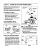
SECTION3: ASSEMBLING YOURSTRINGTRIMMERMOWER IMPORTANT:This unit is shipped without gasoline or oil in the engine. Be certain to service engine with gasoline and oil as instructed in the separate engine manual before operating your mower. Lower Handle Connector Handle Connector NOTE: Reference to right or left hand side of the string trimmer mower is observed from the operating position.
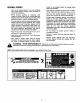
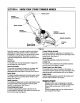
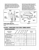
SECTION4: KNOWYOURSTRINGTRIMMERMOWER Control Lever Control Lock Starter Handle Handle Trimmer Deflector Assembly String Cutting Blade Bracket Figure 4 Read this operator's manual and safety rules before operating your string trimmer mower. Compare the illustrations in Figure 4 with your string trimmer mower to familiarize yourself with the location of various controls and adjustments. Save this manual for future referen ce. ControlLever The control lever must be depressed to engage the spindle assembly.
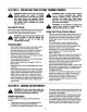
SECTION5: OPERATING YOURSTRINGTRIMMERMOWER 4& trimmer mower can result in foreign WARNING: Debris thrown from the string objects being thrown into the eyes, which can cause severe eye damage. Always wear safety glasses Included with unit or eye shields when operating the string trimmer mower. _p_ control lever. so could result the in WARNING: Do Doing not attempt to bypass serious personal injury or death.
Secure the handle connectors in position by tightening each wing nut (carriage bolts must be seated properly into the handle and grooves must line up between connectors). Also make certain the bottom tip of the upper handle connector in front of the bottom tip of lower handle connector. See Figure 5. * o o o Marked Lines Wing Nut_ The trimmer line is connected to the spindle disc, which can be raised or lowered. See Figure 6.
cleaner, refer to the separate engine manual packed with your unit. The spark plug should be cleaned and the gap reset once a season. Check engine manual for correct plug type and gap specifications. disconnect spark plug WARNING: Always stop wire engine before and cleaning, lubricating or doing any kind of maintenance on your string trimmer mower. ,_ Lubrication ThreadingTrimmerLine Control Lever: Lubricate the pivot points on the control lever at least once a season with light oil. See Figure 7.
DriveBeltRemovalAndReplacement • • • • • Disconnect the spark plug wire and ground it against the engine. Drain the fuel tank or place a piece of plastic beneath the cap to prevent gasoline leakage. If unit is tipped for easier access to belt, tip the string trimmer mower back on its side to keep engine spark plug side up. Remove carriage screws, washers, and hex nuts that secure the trimmer deflector to the base. See Figure 10.
SECTION8: TROUBLESHOOTING Problem Engine fails to start Cause 1. 2. 3. Remedy Spark plug wire disconnected. Fuel tank empty or stale fuel. Throttle control lever not in correct 1. 2. 3. starting position. (If Equipped) Engine runs erratic Engine overheats Connect wire to spark plug. Fill tank with clean, fresh gasoline. Move throttle lever to FAST or START position. 4. 5. 6. Blocked fuel line. Faulty spark plug. Engine flooded 4. Clean fuel line. 5. 6. Clean, adjust gap, or replace.
Model25A-253N401 / 6 3 ! 11 10 27 11 l 12 13 2O 17 i I I I I I I 33 i I I 24 34 ! 25 22 46 14 50
Model25A-253N401 Ref. No. Part No. Ref. No. Part Description Part No. Part Description Control Lever 27. 710-3015 Hex Cap Screw 1/4-20 x .75 681-0166 Engagement Cable Control Lock Bracket 28. 29. 712-3005 710-1694 Flange Lock Nut 3/8-16 Screw 5/16-18 x 1.25 4. 710-0578 Machine Screw 1/4-20 x 1.50 30. 710-1307 Screw 5/16-18 x .75 5. 712-0324 Hex Lock Nut 1/4-20 31. 710-0237 6. 710-1205 Eye Bolt 1/4-20 32. 736-0425 Hex Cap Screw 5/16-24 x .625 Bell Washer .325 ID x .930 OD 7.
MANUFACTURER'S LIMITED WARRANTY FOR: YaRD.MaN TM The limited warranty set forth below is given by MTD PRODUCTS INC ("MTD'_ with respect to new merchandise purchased and used in the United States, its possessions and territories. MTD warrantsthis productagainstdefects in material and workmanshipfor a periodof two (2) years commencingon the date of originalpurchaseand will, at itsoption,repair or replace, free of charge, any part found to be defective in material or workmanship.